Archive for the ‘ham radio’ Category
 Dropping in on MN Section Traffic Manager WØLAW, the Legendary Lawman

Robert Meyer, WØLAW
When I moved out here several years ago, it didn’t take long before my phone rang with a radiogram delivered by Robert Meyer, WØLAW. He lives about a half hour away in the city of Marshall, and is the Minnesota Section Traffic Manager. Robert is a well-known traffic handler, consistently ranking at or near the top of the list for traffic handled each month in this state. He retired as chief jailer of the Lyon County Sheriff’s Office a couple years ago, hence his call sign.
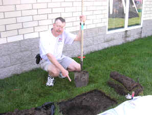
I’d never met Robert in person before, but I’ve wanted to. Having heard through the grapevine that he had just had his new tower’s foundation poured, I decided to look him up last Saturday when I was in the neighborhood for my son’s classical guitar recital. Even though my son and I took him by surprise, he welcomed us warmly and gave us a tour. What a nice fellow!
Robert led us around to his backyard, a beautiful parcel of lush green grass with songbirds feeding tamely at several bird-feeders. A couple of wire antennas hung from his current tower, disappearing into some trees and a river valley beyond. The footing for his new tower, nestled up against the back of his house, was massive!
As we stood there discussing antennas and songbirds, I mentioned to Robert that I’ve always wanted to handle a radiogram but have never mustered the courage to do it. He could have laughed at me, but instead he kindly encouraged me to give it a try and then invited my son and I into his house so he could find “a few things” to help me.
You should see Robert’s shack! When you step inside the front door of his house, it’s in plain view — a most excellent man-cave adjoins his living room. Pretty soon my son and I were marveling at his equipment, stuff we might never see again except in catalogs! Delving into his well-organized file cabinet, in short order Robert came up with a couple of reference sheets and a booklet to help me handle traffic. He also tore off most of an ARRL radiogram pad and gave it to me, refusing to allow me to pay for it.
Click to view slideshow.
I’m grateful for Robert’s hospitality and generosity, not to mention his labor as Minnesota Section Traffic Manager. He represents a side of ham radio that has long been as mysterious to me as the dark side of the moon — QRO SSB NTS traffic handling. Once upon a time I wouldn’t have looked him up, but I think I’ve grown up a little since then. I’ve really come to appreciate the variety of people I meet in this hobby and the variety of activities they do.
Once upon a time my horizon was limited; if you were on HF CW I noticed you, especially if you were QRP, but I didn’t pay much attention to the rest of the ham world. I was cheating myself. I’ve loved CW, but I’m starting to like SSB and digital modes, too. I’ve loved QRP, but I’m also starting to appreciate what QRO can do (and the skill it takes to handle it). I’ve always preferred HF, but as I get to know the local hams I’m becoming surprisingly fond of VHF FM.
So I’m glad I looked up Robert, the legendary lawman — and I’m really glad he welcomed my son and I so warmly. Can you imagine getting a surprise visit from a blogger who snaps a picture of your shack for the world to see? That’s a bit much! Thanks, Robert, for being so nice to us and for being such a good sport.


![]()
Handiham World for 09 May 2012
Welcome to Handiham World.

You can do it!
Today, just as we did last week, we are going to begin with Troubleshooting 101 as part of our initiative to help new ham radio operators (and even some of us older ones) learn how to do some basic troubleshooting for ourselves. Yes, it can be tempting to ask someone else to do things for us. This can become a bad habit when it keeps us from learning new things, especially things that we could – with a bit of practice – learn to do for ourselves. Knowing these basic things can serve us well in the future when no help is available.
Troubleshooting 101

Let’s get to today’s troubleshooting question:
I like using Echolink, and I’ve finally figured out how to forward the ports on my home router to my ham shack computer. The problem is that I can’t use Echolink on any other computer in the house unless I change all those port forwarding settings or use a public proxy, which isn’t always available. Is there anything else I can do to make Echolink a little more convenient?
Echolink is pretty addictive, and it’s easy to understand why you would want to be able to use it all around the house, perhaps even on your laptop while seated out on the patio one of these nice upcoming summer days. As you discovered, when you set up your home router to forward ports as described on the Echolink website, the application will then only work on the computer you selected. The router will happily direct traffic through those open ports, but only to that one specific ham shack computer. As you discovered when setting up your home router, port forwarding is not something you can do on a moment’s notice. You have to log into your router’s web-based administration page, go to the advanced settings, and then the port forwarding section. When you make changes to the settings, the router may momentarily drop internet connectivity and perhaps even reboot. Then it will take a while for everything to settle down and work again. This can be a major aggravation if you have other users in your household or if your home phone is a VoIP system that depends on the internet being connected.
Let’s examine our Echolink application’s built-in Firewall test. You will find it by opening Echolink, going to the “Tools” menu, and arrowing to the “Firewall/Router Test”. Once there, press
Since you have already told us that your ham shack computer has Echolink working, you should get this “Testing Complete” message that says “Firewall test results: PASS”. 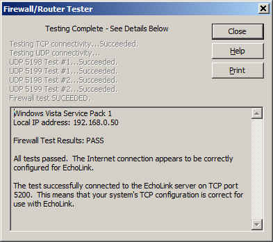
It is important to know about this handy little tool that is built into Echolink because you are going to use it again on a fairly regular basis once you make a few simple changes to your router settings.
Now it is time to use your main computer, which is connected by a LAN cable (preferably) to the router, to open the router’s administration page. Depending on your router’s setup, you will need to log in, then go to the advanced settings page and then to the port forwarding page. This should all seem familiar as you have already done it once. Next, you will need to uncheck the port forwarding boxes that you already set up. Yes, I know it seems crazy, but it is a necessary step. Save the settings, then go back to the advanced settings page and choose “port triggering” or “application rules” this time. It is similar to setting up port forwarding, but there is a BIG difference: You are opening ports when the Echolink application calls for them to carry traffic, no matter which computer on your network is running Echolink. This means that when you open Echolink on your wireless laptop while on the patio, the ports will be open to that computer. When you close Echolink on the laptop and later that evening you go back into the ham shack to use your main computer, Echolink will then work on that one because the ports will be opened by the “trigger” of a call for traffic to that machine.
I happen to have a D-Link router, so a screenshot of the application rules (triggering) page shows that I have triggered ports 5198 and 5199 for UDP traffic and port 5200 for TCP traffic. 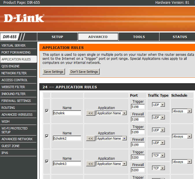
Now I can save the settings and after that I should be able to use Echolink on any computer on my home network without having to worry about port forwarding.
There are some things to remember:
- Only one computer at a time can be running the Echolink application. If more than one computer is running Echolink, only one of them will actually connect properly.
- When you close Echolink on one computer, it may take a few minutes for the network to resolve itself back to a neutral state. If you try to connect Echolink on another machine immediately, it may not work. Always allow a few minutes between switching machines – Both machines may be running and connected to the network at the same time, which is not a problem. It is only starting Echolink too soon after just closing it on another machine that can cause problems.
- This is where we try our built-in Firewall/Router tests again:
If the network is ready, the tests will proceed normally with a “PASS” and you are good to go for Echolink fun!
Email me at [email protected] with your questions & comments. But for the record, please remember that I am NOT tech support for Echolink or your home networking equipment since you are there at home and I’m here in Minnesota. Reading the manual will get you way farther than calling me for sympathetic head-nodding.
Patrick Tice, WA0TDA
Handiham Manager
Jeep Wrangler Radio Install
We recently sold the old white Jeep and bought a 2012 Wrangler (JK). After quite a bit of researching and experimenting with antenna mounting options, I finally got the ham gear installed in it. My objective is to get 2 Meter and 70 cm FM capability into the vehicle, using the Yaesu FT-7800 that I pulled out of the old Jeep. The big question was what to do about the antenna. The fiberglass hardtop does not make for a good antenna ground plane. Even if it did, during the summer months, we’ll sometimes take the top off to enjoy the open air ride.

The 2012 Jeep Wrangler Sport — Can you spot the antenna?
Initially, I planned to use the Arizona Rocky Road NMO antenna mount with a Diamond dualband antenna that is a 1/2 wave on 2 Meters. The 1/2 wave does not need a ground plane, so the performance is usually better with irregular mounting structures. However, I found that this antenna combination did not clear my garage door. I don’t like to have to remove or tilt a vehicle antenna to get in/out of the garage — my experience is that it usually just gets left in the “down” position. I tried a shorter 19-inch dualband whip antenna but its performance was dismal due to these factors: lack of a ground plane, being blocked by the vehicle body and poor grounding on the spare tire carrier. By the way, the grounding issue on the tire carrier (and many other technical topics) are discussed in these online forums: WranglerForum, JK-Forum. I think the Arizona Rocky Road mount would have been my preferred way to go (with the longer Diamond antenna), except for the garage issue. One problem I ran into with that mount is that the standard NMO mounts I have (the basic mounts with the cable attached) did not handle the thick steel of the mount. I had to purchase special NMO mounts made to handle thicker metal (see TheAntennaFarm.com).

The antenna mounting bracket near the hood, driver’s side.
I abandoned the Arizona Rocky Road approach and decided to use a simple NMO mounting bracket (Laird SBTB3400) on the driver’s side hood. Like all Wrangler antenna installations, this is a compromise. It is lower on the vehicle than I would like but it does not block the driver’s view. Other people have used a variety of “trunk lip” mounts to accomplish the same thing but be sure to check out the driver’s view before installing. Installing the mount was easy, just three holes drilled and three sheet metal screws.
The next question was where to install the radio. I took advantage of the FT-7800′s detachable control head, mounting it on the dash, while placing the radio under the driver’s seat. I attached the radio’s mounting bracket to the floor of the Jeep with two heavy sheet metal screws. This keeps the radio up off the floor in case water gets into the Jeep. However, it only provides about 1 inch of water clearance, so you hard core Jeepers that are used to flooding the interior of the vehicle during stream crossings may find this inadequate.

The radio body was installed under the driver’s seat
I have to admit that I ran into a significant problem at this point. There was not enough clearance around the radio mounting bracket to get all four of the screws installed that attach the radio to the bracket. In the end, I unbolted the drivers seat and tilted it back, which gave me room to insert and tighten the screws. More careful positioning of the radio mount might have saved me from this hassle.
It is always a bit of an adventure to find a way to route the power cable from the engine compartment to the vehicle interior. Fortunately, Jeep has made this very easy, but it is not obvious just by looking around. Fortunately, the folks on the various online forums have scoped this out and provided good advice.
I popped off the small side panel of the dash on the driver’s side, to expose a hole filled with foam (see photos).

The plastic panel on the driver’s side of the dash pops open to reveal a routing hole filled with foam
A stiff wire or coat hanger can be poked into this hole and the foam easily gives way.

A coat hanger is shown poking through the routing hole
And the coat hanger comes out the other side, right next to the antenna mount.

Coat hanger pokes through near the antenna mount
I routed the power cable and the antenna cable through this hole. I connected the power cable directly to the battery, which is the recommended approach to avoid alternator whine and other problems. I understand there is a similar routing hole on the passenger side but I did not verify that.
The last thing to figure out was where to mount the control head. Although it is a tight fit, I mounted it in front of the gear shift. (I have the 6-speed manual transmission…the automatic transmission gives you more room here.) The control head is very light, so I used stick-on Velcro (about an inch wide and four inches long) to attach it to the dash. This seems to work OK but I will admit that the attachment is just a bit wobbly…fine for turning volume and VFO knobs but the not so good for pushing buttons. Also, I’ll have to see if it shakes lose on bumpy 4WD trails. If so, I’ll fabricate a small bracket to provide better attachment.

FT-7800 Control Head and Mike Mounted to the Dash
In the process of exploring, I did take the dash apart to figure out what my options were. In retrospect, it was probably unnecessary due to where I eventually mounted the radio and control head. I found this youtube video to be very helpful in dismantling the dash.
Initial checkout shows that the radio installation is working fine. I was pleasantly surprised that the antenna SWR was quite good (<1.5) over the bands of interest. I will use the short 19-inch whip most of the time but I can swap out other NMO mount antennas (including the Diamond dualband antenna I mentioned earlier.)
I appreciate all of the info out on the interwebz concerning JK radio installs and I am passing along what I learned to assist other folks with their Jeep installations.
- 73, Bob K0NR
Update 20 June 2012:
It turns out that the Velcro (hook-and-loop fastener) approach did not work. The Velcro attachment itself was pretty reliable but the stick-on adhesive failed after a few weeks. I used a couple of L-shaped brackets to attach the control head to the dash and it seems to be working fine. I have used Velcro successfully in past installations but in situations where the control head was positioned on top of the center console so the main purpose of the Velcro was to prevent horizontal movement. In other words, the Velcro did not have to support the entire weight of the control head, just keep it from moving around.
Please Consider Donating to Get YMC ARES® Started
 Would you please help launch the Yellow Medicine County, MN Amateur Radio Emergency Services® Group? Even just a few bucks from each of my readers over at amateurradio.com (where this blog is syndicated) would be a tremendous help. I just accepted the position of Emergency Coordinator here, and I’m really starting from scratch. There are only a few active hams in our county right now (I’ll be trying to recruit more, believe me), and we’re strapped for cash. Even with sacrificial spending on our part we’re going to have trouble scraping together the approximately $500 needed to get incorporated and apply for 501(c)3 status. This status will:
- make future donations tax-deductible (helpful when trying to raise money)
- allow ARES® volunteers to deduct mileage and other expenses (helpful when trying to recruit and retain new members)
- make us eligible for grants that are otherwise unattainable
If you would like to donate, just click the button below. I’m using my wife’s PayPal account for now (once we’re incorporated, YMC ARES® will have its own account), but your donation will be tracked and every penny will go toward the YMC ARES® Group. If we reach $500, I’ll post an update right away and take down the appeal for donations in the sidebar of my blog.

Thank you so much for considering this!


![]()
Olivia — the Magic Mode
I have to give credit to Gary L. Robinson, WB8ROL, for the title of this post. I met him on the air tonight using Olivia 500/16, and pretty soon I was reading his article about this mode . . . but I’m getting ahead of myself.

Olivia 500/16. Image obtained from http://www.oliviamode.com.
My introduction to Olivia took place yesterday afternoon at a meeting in a little coffee-shop in Marshall between the MN ARES® ASEC, Section 5 DEC, Lyon Co. EC, and myself (at which I accepted the position of Yellow Medicine Co. EC, but that’s another story). They explained that FLDIGI is the software they are training people on, that every Thursday evening at 8:00 P.M. there is a MN ARES® digital net on 80 meters, and that they are using Olivia 500/16 for this net.
Well, my power of recall being what it is, I’d forgotten all about it till I heard the clock chime 8:00 while I was doing the dishes (after dining on my wife’s fabulous slow-cooked chicken). “Honey,” I asked, “would you mind if I left the rest of the dishes to you? I’d like to go check out a net on the radio.” I sure am blessed with a sweet wife — she took over without batting an eye while I dashed downstairs and started hooking up my laptop to the interface while firing up FLDIGI.
Sure enough, there was the net. I “listened” (How do you say it? Read?) for nearly an hour, and finally checked in right as the net was closing.
Well, tonight before going to bed I decided to try it again. This time I went up to 20 meters where I had a nice ragchew with Gary, WB8ROL (my first “real” QSO). We hit it off right away — his career path took him from law enforcement to programming just like mine did, we both have bad backs, and we both like cats and penny-whistles — but what really got my attention was his website: www.oliviamode.com. This fellow is a veritable evangelist for this mode! If you haven’t read his QST article about Olivia, click here and enjoy “Ghost QSOs — Olivia Returns from the Noise.”
I can attest to what Gary writes about in that article. As the band began to fade, his signal dropped until I couldn’t hear it at all. All I could hear was static; I assumed I’d lost him. Not only couldn’t I hear him, I couldn’t see anything on the waterfall display. But incredibly, letter after letter appeared on the screen as Gary typed his last message!
Olivia really is “the Magic Mode!”


![]()
Finished With First Half of the Electronics Learning Lab (with Guest Blogger Antonio)
My son, Antonio, has reached the midpoint of his work with the Radio Shack Electronics Learning Lab I wrote about last November. Just a few days ago he finished the first of the two workbooks (click here to view PDF). I really liked the second-to-last of the labs — a “fully adjustable siren.” Here’s the schematic, followed by my son’s take on this part of his homeschooling curriculum:

The End of Book One of the Learning Lab
The last lab of book 1: a frequency meter using 555 & 4046 chips.
I have reached the end of book one. It has taken me six months to complete the book. The things that I have learned are both great and valuable. To be able to understand parts (such as resistors, capacitors, and different types of ICs) has been a great help.
It has been a real joy to have my dad help me with my projects. We both learn something new each time we do a lab. With this lab you learn how to put together circuits. You also learn to think about what the circuit is doing. Once you really start to understand the basics you are able to figure out parts of the projects without looking at the step-by-step instructions.
Grade: A!
This lab kit has so many neat and interesting projects. You get to build things like light-dark meters, adjustable sirens and so much more. By using this lab I am able to build a code oscillator and many other useful things. Anybody who wants to know more about electronics or who has never learned about them should consider getting one of these lab kits from Radio Shack. Once again let me just say that I have really enjoyed working with this lab.


![]()
Handiham World for 02 May 2012
Welcome to Handiham World.
You can do it!
Today, just as we did last week, we are going to begin with Troubleshooting 101 as part of our initiative to help new ham radio operators (and even some of us older ones) learn how to do some basic troubleshooting for ourselves. Yes, it can be tempting to ask someone else to do things for us. This can become a bad habit when it keeps us from learning new things, especially things that we could – with a bit of practice – learn to do for ourselves. Knowing these basic things can serve us well in the future when no help is available. This next simple exercise is one that we will be practicing at this summer’s Radio Camp. You can do it yourself once you learn a few basics.
Troubleshooting 101
I have my General Class license now, so I decided to put up a vertical antenna, which I ground-mounted, in my back yard. I have checked the SWR (standing wave ratio) and it is practically one to one. It is grounded with a ground rod right near the feedpoint, and I have kept the grounding wire short. I am putting out plenty of power with my 100 watt rig, but I am having a hard time making contacts? What is wrong here?
Vertical antennas have long been the subject of derision in many amateur radio circles. It is practically an article of faith that “a vertical antenna is one that transmits equally poorly in all directions”. These operators have either tried vertical antennas themselves and had a poor experience or (more likely) they have heard some know-it-all pontificating on the awfulness of verticals and the awesomeness of just about any antenna other than a vertical.
Yes, the poor old vertical has gotten a pretty bad reputation. But is it justified?
I say no! And here’s why.
The most common vertical antenna design is an electrical quarter-wave long. This means that a simple 20 meter vertical will be on the order of 16 to 17 feet tall (5 meters). There is no problem ground-mounting a vertical in most locations, and this kind of antenna is sometimes disguised as a flagpole in places where there are restrictions on traditional antennas. A ground-mounted vertical will certainly have other advantages, too. It will not require an expensive tower or other supporting structure. It will be easy to install and work on if it needs maintenance or adjustment because you can reach it without any climbing. You can trench the coaxial feedline under the ground to keep it out of the way. If it is mounted in the back yard, it will probably not even be visible from the street. No wonder this simple antenna seems so attractive!
But let’s get back to your troubleshooting question. You have done well with your vertical antenna installation as far as it goes, but you have made a common mistake. You have assumed that a ground rod would suffice as a complete grounding system – but it won’t. When we work with RF (radio frequency) energy, we must remember that RF grounding is not the same as providing a simple electrical ground for low-frequency AC, DC, or lightning protection. Yes, a good electrical ground is an essential part of a well-designed antenna and feedline system. Now it is time to complete your vertical antenna installation with a good RF ground. That means installing radial wires extending from the base of the antenna outward in all directions. The ground rod should work as a common connection point. The coax braid is connected to the ground rod or the antenna’s mounting post, both of which are tied together with a stout, solid conductor.
What is happening in your antenna system is that lots of current is flowing in the vertical element right near the feedpoint. This is normal and expected. There is also a lot of current flowing in the ground beneath and around the antenna, outward in all directions. That is because a quarter-wave vertical is like one side of a dipole system, except that the ground makes up the other half of the dipole. If you recall your General Class studies, you will remember that current in a half wave dipole flows most strongly right near the feedpoint.
Now, answer me this: If you put up a dipole with one leg made of a fully-extended wire and the other a very short wire connected to a big resistor, do you think that dipole would work as well as a dipole with both legs made of wire?
No? Why not?
“Well”, you say, “It is obvious that the dipole with a big resistor in it will not work as well because there will be power lost in the resistor. The resistor will heat up, just like a dummy antenna.”
Yes, you are right! In fact, dummy load antennas are really nothing more than resistors designed to dissipate RF energy to keep it off the air while you run tests on a transmitter. A dummy load will have a near-perfect SWR, even though it is a resistor. Just because it has a low SWR does not mean that it is a good antenna. The problem with your vertical antenna system is that it is like that dipole with a resistor in one leg. The ground beneath the antenna has resistance to the flow of RF energy outward in all directions. The soil does have some conductivity, but it depends on moisture and composition. So the ground can be like a resistor. The ground rod you have installed goes straight down and does nothing to help RF flow in all compass directions outward near the surface of the ground.
The fix: A good radial system.
Radial wires are installed like the spokes of a wheel, outward from the grounded side of your antenna’s feedpoint. They can be cut to a quarter-wave length for every band you plan to operate (if your antenna is a multiband vertical) or – and this is more practical – to whatever length is convenient to fit into the space you have. Mind you, this goes only for a ground-mounted vertical in an area with normal to good soil conductivity. If you are mounting a vertical over quartz rock with almost no soil, the tuned radials might be necessary. If you are in the USA Midwest with its rich soil, you can probably get by with random length radials in your ground-mounted system. The reason is that conductive soil pretty much detunes the radials anyway, so there is nothing to be gained by carefully measuring them. In fact, since most of the RF current will be flowing right near the feedpoint, it makes sense to provide it with a low resistance path there, close to the antenna.
Why? Think of the formula power dissipated = current squared times resistance. The higher the resistance in the ground, the more power will be dissipated as heat. You don’t want that! What you want is for most of the power to be used to make contacts with other stations. The earthworms will be happier, too, because they don’t need the extra heat. If most of the current flows in the ground near the antenna, then THAT is where you need to put the most radial wire. I have always simplified this concept when teaching about vertical antennas by using the following practical example:
You have a coil of wire to use for radials. It is 100 feet long and will provide the radial system for your 20 meter band quarter-wave vertical. The question is which of these choices would be better:
A. One long radial that uses all 100 feet of wire.
B. Two 50 foot radials running in opposite directions.
C. Three 33 foot radials spaced 120 degrees apart.
D. Five 20 foot radials spaced at 72 degrees apart.
If you were thinking about losses near the feedpoint, you would probably pick answer D. The reason is that you are putting more wire near where the loss is actually happening! In fact, the thing with radials is “the more, the better”, not “the longer the better”. Of course you would not want to go to extremes and assume that 100 one-foot radials would work. But in the real world, you want to get more wire down in the ground near the feedpoint. A dozen radials work better than four.
Installing and testing the system:
Stomp the grass back down and you are good to go. Repeat for each radial. If you can go out 33 feet in one direction and only 15 in another, that’s okay. Just make sure that the final installation is solidly connected to the ground rod and coax braid and all of the wires are out of the way of the lawn mower. The insulated wire will last longer in the ground than non-insulated wire. Once you get a taste of a hands-and-knees radial installation, you will not be eager to repeat it to replace rotted out wire any more than you have to. And if you tried to install springy radial wire, well, you know what that is like. Push one part in, another part pops out.
Email me at [email protected] with your questions & comments.
Patrick Tice, WA0TDA
Handiham Manager


