Archive for the ‘antenna’ Category
 DIY Magnetic Loop Antenna – Part 2
Part 1 of the DIY Magnetic Loop Antenna covered mostly theory and materials so now its time to move on to designing the magnetic loop antenna (MLA).
If you have priced a commercially made MLA you’ll see prices start at $400 and keep going up, and up. If they cost so much you would think they must be difficult to build or use expensive parts, right? Well, it is certainly possible to spend more and get a higher quality MLA but a low cost MLA will still work very well.
For the purposes of this article we’ll assume that you want to build a loop to cover the 20-10M bands. I’ll run through the calculations required to build the MLA.
The required information for the MLA calculator is:
- Length of the loop
- The conductor diameter
- Frequency/s of operation
- Input power to the antenna
- We don’t really know the best length of the loop at the moment so I’ll pick 9 feet circumference as a starting point (It’ll still fit in the trunk of my car)
- Since we seem to be having better luck with sunspots now I’d like to try 10M so we’ll start with 29 Mhz as the highest frequency we’ll use.
- I have some copper pipe left over from an ice-maker install, it is 1/4 (0.25) inch in diameter.
- Input power to the loop will be 100W.
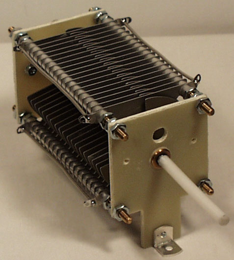
 A peak voltage of 5181V will require a minimum spacing of 1.7 mm (peak voltage / breakdown voltage per mm) between the closest conductors in the capacitor. That would rule out an old air spaced variable capacitor from a vacuum tube radio but you could still use a wide spaced variable capacitor from an antenna matching unit or transmitter. A vacuum variable capacitor would be great (watch the minimum capacitance) or a home-made capacitor would also be fine provided you checked the breakdown voltage of the insulating material.
 DIY Magnetic Loop Antenna – Part 1
Do you live in a neighborhood with a restrictive antenna policy and despair of having a useful HF antenna?
Can you solder or know someone who can?
A magnetic loop antenna may be the answer and they are not as difficult to build as you might think. Like getting on the air for the first time or taking your license exam there is a certain amount of uncertainty when you first approach magnetic loop antennas, there are a few new ideas to grasp. However, thanks to other hams like Steve AA5TB there are tried and tested designs, calculators & building methods that are known to work and that you can follow.
 At the heart of every radio and MLA (Magnetic Loop Antenna) is the resonant circuit. The combination of an inductor (a wire has inductance, but a coil of wire has more) and a capacitor (two conductors separated by an insulator) in a circuit will resonate or ‘ring’ at a certain frequency. Sound vibrations at a certain frequency can cause a piano string to vibrate in sympathy and a vibration of the correct radio frequency will cause a resonant circuit to electrically vibrate in sympathy.
Since there is no such thing as a free lunch, the sacrifice you make with a MLA is that it needs to be re-tuned whenever you change frequency on your transceiver. The frequency range over which it is resonant is very small, typically only a few hundred kilohertz at the most.
The materials you can get your hands on is going to decide the capabilities of your MLA. Ideally you’ll have a loop made from a conductor with very low resistance (usually copper) and a capacitor that can handle high voltages. A variable capacitor is required if you want to use your antenna on multiple frequencies but you can use or make a fixed capacitor if you operate on one frequency, for Eg PSK31.
A MLA calculator like the Excel spreadsheet from Steve AA5TB or this web page from 66pacific.com will help you to decide what size components you’ll need to make your antenna.
The four pieces of information required are:
- What frequency or frequencies do you wish to transmit on?
- How large do you want the loop to be (It should have a circumference less than 10% of the design frequency wavelength, both calculators help you figure this out)
- The diameter of your conductor (Three quarter inch (0.75 inch) copper pipe is a good start)
- How much power you want to use (The voltage across the capacitor is proportional to the input power to the MLA)
 A MLA of a certain circumference will be more or less efficient based on the frequency you transmit at. It is worth changing the loop size in the calculator to get the best efficiency possible in your favorite band.
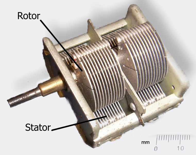
Portable 50Mhz antenna
One of the enduring aspects of amateur radio is the emphasis on ‘experimentation’ and ‘homebrew’. To many people this means designing innovative circuits for their own transceivers, amps or whatever floats their boat. My area of interest is in collecting either bent wire, off cuts of cable and odd shaped plastic parts scavenged from just about any skip or rubbish bin I can find. Some people like to call this antenna experimentation. My XYL likes to call it ‘That junk in the garage’. I like to call it my continued education. Below is a teaser!

The latest in my armoury of ‘stuff I’ve done’ will never help anyone chase DX or bust a pile up for a little activated square or something else. But it will give me another band to work with when I’m away from home, either on top of a summit, at the mother in laws or operating portable in the summer Es season (I say summer because the top of St Bees head isn’t very welcoming in the winter as I found out whilst operating GB4LBC).
My take on the 5/8 wave 6m vertical originally published by the UKSMG by Mike, G3JVL took a little over a weekend and was made relatively cheaply from scrounged resources. I enjoyed the job so much I’ve added a little project page here which I hope you enjoy. Feel free to try it out yourself and improve on the design path I took, let me know how you got on with the manufacturing of what should be a nice project (that can also be cheap if you’re scrounging skills are up to scratch)
Weekend 50Mhz vertical antenna
One of the enduring aspects of amateur radio is the emphasis on ‘experimentation’ and ‘homebrew’. To many people this means designing innovative circuits for their own transceivers, amps or whatever floats their boat.
My area of interest is in collecting either bent wire, off cuts of cable and odd shaped plastic parts scavenged from just about any skip or rubbish bin I can find. Some people like to call this antenna experimentation. My XYL likes to call it ‘That junk in the garage’. I like to call it my continued education. Below is a teaser!
The latest in my armoury of ‘stuff I’ve done’ will never help anyone chase DX or bust a pile up for a little activated square or something else. But it will give me another band to work with when I’m away from home, either on top of a summit, at the mother in laws or operating portable in the summer Es season (I say summer because the top of St Bees head isn’t very welcoming in the winter as I found out whilst operating GB4LBC).
My take on the 5/8 wave 6m vertical originally published by the UKSMG by Mike, G3JVL took a little over a weekend and was made relatively cheaply from scrounged resources. I enjoyed the job so much I’ve added a little project page here which I hope you enjoy.
Feel free to try it out yourself and improve on the design path I took, let me know how you got on with the manufacturing of what should be a nice project (that can also be cheap if you’re scrounging skills are up to scratch)
Delta Loop for 10 Meters on a Buddipole

- Vertical Polarization

Horrizonal Polorization of Delta Loop Good for DX
The magic that makes this antenna possible is a TRSB, Triple Ratio Selectable Balun. There is a 2:1 ratio position on this balun that is reversed for a 1:2 ratio to match the coax to the 100 ohm antenna. Any balun with this ratio will work.
-

- Vertical Polorization, Good for Talking to Mobile Ops
-

- Horrizonal Polorization of Delta Loop Good for DX
-

- End of whip burinshed to metal base with Dremel tool
Ten meters is doing pretty good lately. It sure is nice to have this band open again. I worked Alaska and Argentina on 10 meter CW using this antenna. I replied to an Ea7 station on SSB but he didn’t hear me.
The Delta loop is easy to configure and easy to deploy. These photos were taken on the porch of my condo. I’ll take this delta loop to the beach when the WX clears. I needed a rainy day to catch up on things around the house.
For more information on Buddipole Delta Loops; join the Yahoo Buddipole group
Here’s a nice video featuring a Buddipole Delta Loop http://www.youtube.com/watch?v=Ikm-HICGcrI&feature=youtu.be
This antenna can be used on 12 meters also and on 15 and 17 with additional Buddipole Arms and a longer ‘home brew connecting wire’ to close the loop.
I’ll be trying these bands out at the beach, my usual ham radio portable venue.
73
de AA1IK
Ernest Gregoire
A Different Kind of Antenna


My latest antenna project turned out very well. I took it to the beach for an on the air test this afternoon. This magnetic loop antenna tunes from 40 meters through 15 meters. In my haste to get to the beach, I forgot my antenna analyzer. After setting up the Mag Loop, I turned on the radio, turned the volume up full blast, and tuned the antenna for the loudest noise. Bingo!!
I was on the air. It couldn’t have been simpler.
The antenna is made from 3/8 inch copper tubing, 1 1/2 inch PVC pipe and a few odds and ends from Radio Shack. The heart of the antenna is an air variable tuning capacitor, 11 to 300 Pfd. The large loop, (the main loop) is fed with a half Faraday feed loop. All the information for building this antenna is readily available on line and partially from the ARRL antenna hand book.
Good links for Magnetic Loop builders: http://aa5tb.com/index.html,
http://groups.yahoo.com/group/CW-QRP-HOMEBREWERS/,
http://groups.yahoo.com/group/MagneticLoopAntenna/messages
My next Mag Loop will be 5.5 feet in diameter and made from 5/8 inch copper tubing. More on this as it develops!! There was an unexpected bonus in the speed and ease of setting up an antenna for portable use. I was on the air in minutes after getting out of the truck.
Please feel free to contact me if you are interested in building one of this fantastic antennas. The antenna has a very high Q so it has a steep tuning notch.
If you use a Faraday loop to feed it, it will be very directional. You can also use a Gama match instead of the feed loop, to feed the antenna. How did it work? I made a very nice contact on 15 meter CW with a ham in Milwaukee this afternoon. Not bad for 5 watts, an small antenna for a contact from Florida. The QSO ended with air boat QRN! The air boat passed by close to shore and I was on the water’s edge about 100 feet away. Next time I’ll bring the Bose noise cancelling headphones!!
De AA1IK
Ernest Gregoire
Geezer in the park
LHS Show Notes #067
Introduction:
- It’s a ramblin’ show tonight.
Announcements:
- Texoma Hamarama 2011 will be October 21-22, 2011 at the Ardmore Convention Center, 2401 North Rockford Road, Ardmore, OK. Richard hopes to be there.
- If you attended the Huntsville, AL hamfest in August, let us know if you think it would be a good venue for LHS.
- Thanks, as always, to Gamma Leonis for the theme music.
Topics:
- Russ talks about the antenna feedline window passthrough panel he bought at Dayton. He’s also hoping to get a radio in his truck. Richard describes the window passthrough methods he’s used in the past, with foam pipe insulation or air conditioning insulation foam.
- Richard talks about the lack of ham radio activity in his area (Kaufman County, TX): no club, no RACES group, no ARES, etc. He called his ARRL SEC (Section Emergency Coordinator), Walt, KG5SOO, and learned that the local groups weren’t happy with the current ARES manager. The SEC says paperwork is being processed and the new emergency coordinator of Kaufman County, TX is Richard, KB5JBV! Currently, there are just two ARES members, Richard and the Emergency Manager, so if you’re in Kaufman County, TX, get in touch with Richard! (Congratulations, Richard!)
- There’s a new podcast out there: Richard’s Radio Adventures. Look for it on the Resonant Frequency feed.
- In Linux-related news, Russ lets us know that kernel.org was hacked a few weeks ago. Because the code was in an encrypted git repository, it was safe, but they moved it to github, anyway.
- Russ also says there was a brief period that GNU Emacs was packaged and distributed with a binary blob in it, which violates the GPL. It’s since been fixed.
- A security hole in SSL/TLS has been reported.
- Simon, HB9DRV, has sold the rights to his Ham Radio Deluxe software. Our hosts discuss the possible ramifications.
- Richard wanders into a discussion of Arch Linux. It seems there was an issue with Arch not being free (as in speech). However, Parabola GNU/Linux is Arch, but free of all the entanglements.
- If anyone out there is an Emergency Coordinator or Assistant Emergency Coordinator, send an email to Richard about how your EC is going. Richard is looking for advice on how to best set up the ARES EC organization in his county.
- Russ admits that his other podcast, QSK Netcast, has stalled, mostly due to a lack of his available time.
- Since some parts of the LHS website are now subscription only, Russ began researching SSL certificates. He found a couple of places that issue inexpensive or free browser-compatible certificates: CheapSSLs , under $10 per year, and StartSSL will issue personal certificates for free.
- Russ and Richard discuss their love for the Sansa Clips. Russ likes DoggCatcher for listening to podcasts on his Android phone.
- Richard talks about his secret antenna project. He’s now in an area with Codes, Covenents and Restrictions (CCRs) which preclude outside antennas. Years ago, he bought an Arrow dual-band J-pole antenna, and used it for packet and other stuff. Using some military surplus olive-drab fiberglass tent poles, he strapped the J-pole to the top of the tent poles and the poles to the top of an 8′ fence. He assures the neighbors that it’s just a flower pot hanger.

Contact Info:
- Contact Richard at [email protected], Russ at [email protected], or both at the same time at [email protected].
- Listen to the live stream every other Tuesday at 8:00pm Central time. Check the LHS web site for dates.
- Leave us a voice mail at 1-909-LHS-SHOW (1-909-547-7469), or record an introduction to the podcast.
- Sign up for the LHS mailing list.
- Sign up for the MAGNetcon mailing list.
- LHS merchandise is available at the Merch link on Web site. Check out the Badgerwear or buy one of the other LHS-branded items at PrintFection.com/lhs or Cafe Press. Thanks!
- Thanks to Dave from Gamma Leonis for the theme music.


