Archive for the ‘antenna’ Category
 Lighter yagi’s
Over the summer I managed to ‘do’ 2 out of the 5 available 2m Backpacker contests. These to me are a great opportunity for me to get out on the fells and enjoy a longer spell on a summit with a nice qrp rig and some simple gear. The trouble with contesting is that inevitably you want to do better. So what’s the likely areas for improvement. Well there’s the rig, coax and antenna.
The rig is an ft817 and its not going anywhere fast. I sold once once then instantly regretted it. So it’s not going to be changed in a hurry. Yes it has its problems but frankly it just works and is relatively light so its a keeper.
Coax…Hmm work in progress. RG213 is too heavy, Ecoflex just isn’t flexy enough for summit packing. I’m yet to find the ‘perfect coax’. I’m leaning towards a trial with some Messi & Paoloni Ultraflex 7 as I like Mini 8 as a size but am looking for perfection here kids. This just means a reduction in losses to something as low as reasonably practicable as the saying goes
Antenna. Well I do like my now obsolete Sotabeams SB270 ( A 3 element yagi that lives inside its own plastic boom). Its light and doesn’t get thrown about too much in the wind and has lasted years. Trouble is it’s looking a bit knackered now and 3 elements is a bit short. I bought a 5 element LFA off innovantennas years ago and was really disappointed with the build quality. The elements just weren’t secure enough and it was way too heavy. Too heavy for a UKAC /p so no good for a summit. But it is well designed and the elements are quite light.
So the plan is to change the coax. I’ll do that over the winter. In the mean time I’ve taken a few grams off the yagi.
The boom was very substantial 32mm2 2mm thick Aluminium (note spelling you stupid browser ;-)). The boom weighs in at 1150g as is.Swapping this for 20mm2 1mm thick boom I’m down to 560g. Roughly half the weight. Element clamps have been swapped for the G1YBB method of IML mouldings plates and cheapo pipe clamps

You can see the immediate difference in size. The original beam is clearly made for sticking up at home then forgetting about it, ignoring the defects with this particular one.
Now with the elements added. They simply snap in to the pipe clamps and are held in place without any bother.

We’ll see how easy it is to carry up the Old Man of Coniston next year but at 1240g it is nearly 500g lighter than the original with the same RF performance.
I bought 2 pieces of aluminium and have a larger 2m and 70cm DK7ZB yagi that needs the same treatment (I went the other way this time, it was too light and flimsy) that I’ll give a run out during the Christmas Cumulative content
Vertical antenna on a turf roof
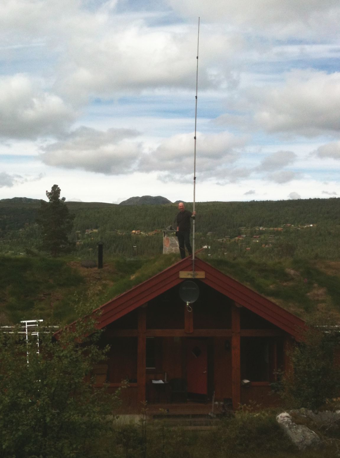
A vertical wire antenna based on a MFJ-1904H 6.7 m (22 feet) telescopic fiberglass pole as shown here is easily tuneable for all bands from 40 m to 10 m. Here it is placed on top of a turf (sod) roof with quarter wave radials for all the 7 bands going to each of the two sides sloping down as they follow the contour of the roof. The antenna seems to work satisfactorily at least on the 30, 20, and 17 m bands which I have been able to test so far.
A turf roof is a traditional Scandinavian type of green roof covered with grass. It dates back to the Viking age and before. In modern times it has seen a renaissance in e.g. mountain cabins.
But how does the turf affect the antenna or to pose the question more precisely: Can it be used to improve the ground plane and the antenna’s performance?
The $20 Software Defined Radio
Despite my interest in boat-anchors I do find myself peeking ‘over the wall’ from time to time and taking a look at new and emerging technologies. After several demonstrations from friends I had become convinced of the incredible potential of software defined radios and even found thinking about owning one … one day.

Software (Linux) : After poor results with the software running on MS Windows I moved across to Linux and got it working well there. I can’t point you to a single howto for this because I used several different guides and tried a few things before it started working. The most helpful, and probably all you really need, are the build-gnuradio script which gets hardware support and gnu-radio running and the “Getting Started With RTL-SDR” page by Tom Nardi which covers installing Gqrx. All the software used is in development and requires familiarity with the command line to install and use at the moment.
Update : Thanks to a link from Neil W2NDG to an EBay sale I’ve been able to track down a pre-assembled HF up-converter on this page : New HF Converter Kit for the SDR Fun Cube Dongle The price seems to be 45 euros, or about $55 US.
B&Q Beam
I’ve committed to ‘presenting’ the B&Q beam to the club in a couple of weeks so I better get on making it. The idea is one that has been done a few hundred if not thousand times over. Give some new / inexperienced hams the opportunity to build a perfectly adequate 3 element beam for 2m from parts found at a local hardware shop. In the UK B&Q is just about everywhere and it supplies just about everything, apart from the thing you want, generally.
Seriously the design is taken from any of your favourite calculators. I have found that they vary slightly against the original maths but I know my Sotabeam works very well so that’s a good starting point for dimensions.
Costs to date are in the region of a few quid but by far the most expensive parts are the nylon bolts used to hold the elements. I’ve bought a bunch so I’ll have a few attempts at drilling straight through the nylon without heating it up too much.
Ham Radio and Mesh Networks
Lately I’ve been fascinated by the capabilities of mesh networks. The ability to quickly create ad-hock computer networks could be an invaluable resource for amateur radio operators in general and particularly for emergency communications (EMCOM)

The particular device and software I have been experimenting with is the Linksys WRT54G router and HSMM-MESH firmware from http://hsmm-mesh.org/.
Installing the HSMM-MESH firmware changes the way the Linksys router functions and allows it to automatically connect to other HSMM routers in a mesh network. No special configuration is required after setting your callsign. All TCP/IP configuration is pre-configured, even down to automatically assigning addresses to connecting clients.

Mesh networks are highly fault tolerant. Every router in the network is aware of every other router and has the ability to move network packets through from one unit to another provided there is a link, or chain of linked routers, between them.
In the diagram to the right each router is represented by a numbered circle. If router number 6 were to fail then network packets that needed to move between router 1 and 7 would travel through routers 2 & 3 or 5 & 10 until 6 was repaired. All this happens automatically and quickly enough so that there is no disruption to the traffic.
Anything you can access on a normal computer network can be made to work on a mesh network. Some of the services that have been demonstrated include email, voice over IP (VOIP), video conferencing, file sharing, web servers & groupware applications.
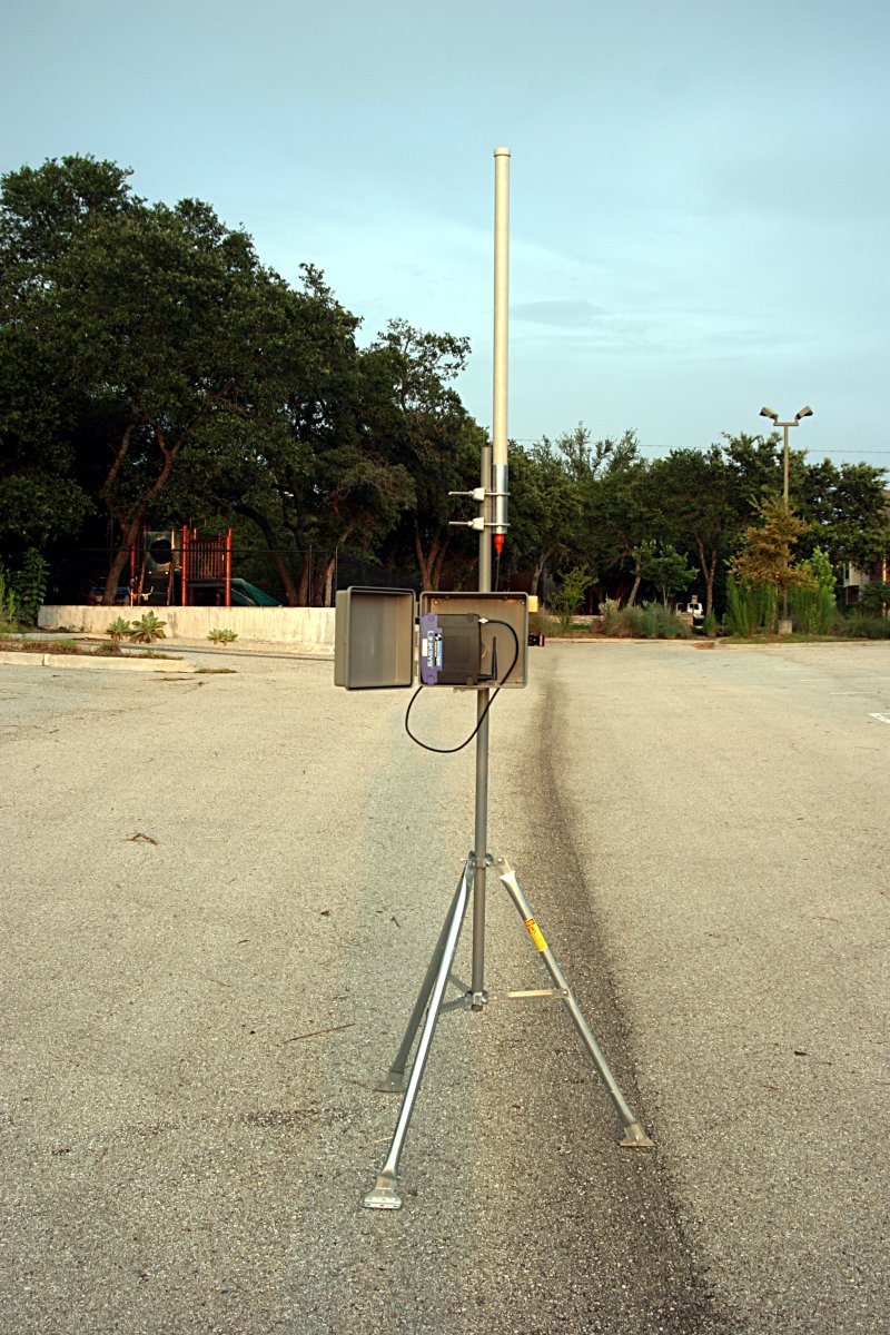 With simple modified antennas the modest output power from the WRT54G (100 to 200mW) can be used to reach distances of many miles or tens of miles with directional antennas. Mounting the router on a mast in a sealed enclosure can reduce losses from long cable runs while running off 12V power makes them compatible with ham radio power sources including solar and wind power.
The example to the left is from NG5V located on hsmm-mesh.org and consists of an omni-directional external antenna and a lawn sprinkler controller box from a popular home improvement store.
Did you know that … Frequencies used by channels one through six of 802.11b and 802.11g fall within the 2.4 GHz amateur radio band. Licensed amateur radio operators may operate 802.11b/g devices under Part 97 of the FCC Rules and Regulations, allowing increased power output but not commercial content or encryption.
I hope to acquire a few more WRT54G routers and put together a mesh network in the Katy TX area as a resource for experimentation and education in an area not normally touched upon by regular amateur radio operators. Who knows what the future holds & it behooves us to investigate this technology and bend it to our own needs.
The Amateur is Progressive … He keeps his station abreast of science. It is well built and efficient. His operating practice is above reproach.
DIY Magnetic Loop Antenna – Part 3
Well, I finally have had time to sit down and put together part three of the DIY Magnetic Loop Antenna, sorry it has taken so long!
This post will cover building and coupling the loop to your transceiver. After reading through posts one and two you should have a good idea of the parts you’ll use and the physical dimensions of the main loop.
DIY Magnetic Loop Antenna – Part 1
DIY Magnetic Loop Antenna – Part 2
Most magnetic loops have the capacitor at the top of the main loop and the gamma match or matching loop at the bottom, this arrangement avoids running the feed-line through the center of the antenna.
You can assemble the main loop from continuous copper tube or from eight straight sections and 45 degree joiners. Make sure you have a blow torch or propane torch to solder the joints as you’ll need more heat than a soldering iron can supply. Whichever way you decide to build the main loop make sure that all joints are soldered or clamped as securely as possible, you want the lowest resistance possible to avoid your output power turning into heat. Other materials can be used for the main loop such as aluminium or low loss coax but copper pipe is easy to work, has low resistivity and available from just about every hardware store.
To construct the frame of the antenna you can use PVC pipe. It is a cheap and relatively sturdy building material and is available in a range of thicknesses, just about any hardware store will stock a wide selection of fittings. It insulates well and can be glued once you are sure your project is in its final form.
Once the main loop is constructed you’ll need to connect your capacitor to the two ends of the pipe at the top of the loop. Depending on the capacitor you may want to solder tags to the ends of the loop so they will be easier to attach. Copper pipe is a great conductor of heat and takes a lot to heat up and solder while it is not advisable to apply the same amount of heat to your capacitor.
It is also a good idea to attach the capacitor to a solid support so that the connections are not under strain.
The main loop and the capacitor forms the resonant circuit of the magnetic loop antenna.

To couple the main loop to your transceiver and match the expected 50 Ohms impedance you can use one of two methods. Probably the easiest is to use is a loop of insulated wire 1/5 the circumference of the main loop. The smaller loop is placed at the bottom of the main loop and can be shifted around to provide the best match. If you have an antenna analyzer you’ll be able to set it to the desired frequency, tune the variable capacitor for resonance and then move the small matching loop around till you have achieved close to 1:1 SWR. If you don’t have an antenna analyzer you can tune the capacitor for the greatest received noise and then on low power tweak the capacitor and move the coupling loop around for best SWR. Do NOT touch the loop while it is transmitting, use a wood or plastic rod to make adjustments as there are high voltages and intense RF fields near the loop.
An alternative to the coupling loop is the gamma match. The shield of the coax feed cable is connected to the base of the main loop while the inner conductor is connected to a point approximately 1/5 of the circumference around the loop. Its a good idea to use stiff wire (large gauge) for the gamma match as it can be critical of the position and orientation and once you have it in the right position you won’t want to move it again.
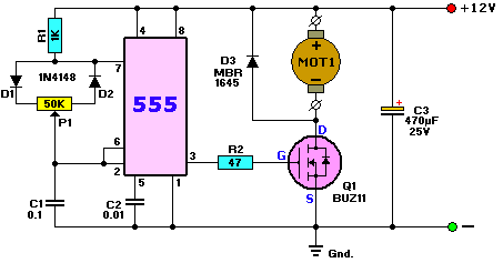
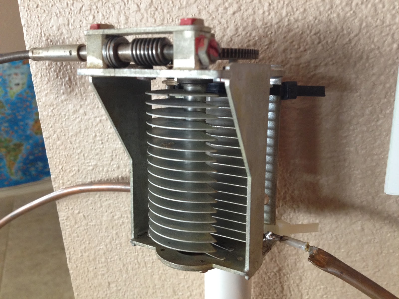
It would be preferable to have the ability to remotely tune the loop. A motor with a reduction gear could be used to move the variable capacitor but because the point of resonance is very narrow there should be a way of slowing the motor down. A simple control circuit using variable pulse width modulation could be used to slow the motor down while still retaining enough torque to move the capacitor. Whatever method is used to move the capacitor it should be well insulated from the other components of the antenna. Several thousand volts are generated on the MLA and care should be taken to ensure they don’t find their way onto control leads and back into the shack. Control leads should also be wrapped around toriod inductors as they leave the near field of the antenna to reduce the possibility of RF travelling along them.
With a SWR bridge and microcontroller you could build a fully automatic tuner that swept through the range of the tuning capacitor when the SWR rose above a defined limit indicating that the transmit frequency had changed.
With a little creativity and knowledge you could have an impressive MLA the equal of multi-thousand dollar military style units.
Hopefully this has given you some ideas for constructing your own loop antenna. Regardless of if you go top-of-the-line and buy a vacuum variable or build for economy and QRP you’ll have a compact, useful and unique antenna.
What has been happening?
Anyone looking at my blog could be forgiven for thinking that I had dropped off the face of the earth for a while, has nothing been happening in my world?
Well, the answer is that a LOT has been happening and all at once. My daytime job has become busier and there have been several non-radio projects at home that needed to be completed. All this has kept me away from Amateur Radio blogging even though I have spent more time on the computer than usual.
In between projects I did manage to stumble across this video of Rear Admiral Grace Hopper explaining just how “long” a nano-second is and what it looks like. This has relevance to radio as we’re usually well aware of frequency and wavelength but don’t usually spend too long thinking about speed.


