 |
 Barn Door Wide!
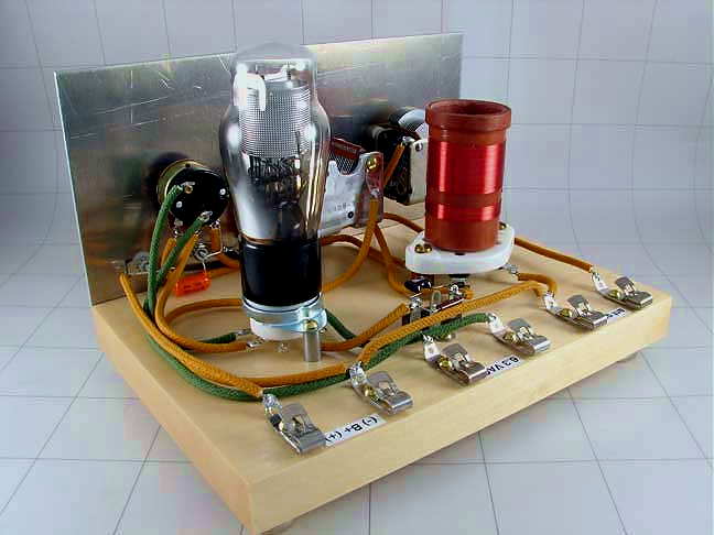 |
| Alfred Morgan 1 Tube Regen courtesy: KC9KEP |
The next CLE event will be the "Barn Door" listening activity which requires listeners to use receivers without the usual narrow filters. Some of the older tube radios can do this easily as can most homebrew receivers ... especially the regens!
If you've never listened to the NDB band with a wide bandwidth, it is a fascinating experience! If conditions are normal, you can typically hear a half dozen or more signals, all at various pitches, vying for your attention. It's almost as if you have plunked yourself down in the middle of the NDB forest of signals, and they are coming at you from all directions.
Many choose to use one of their homebrew receivers for this event, often as simple as a '1AD' or a '1 Active Device' circuit. A recent posting to the ndblist group from CLE organizer Brian Keyte (G3SIA), described just how much fun can be derived from such a simple radio. I'll let Brian's words speak for themselves below:
Recently I've had a few requests to provide details of my 1-transistor receiver, as used on my recent Scotland holiday and back in April 2009 for our first CLE for simple receivers. (There's still time to try making something for our next CLE145).
Here goes:
In March 2009 I was tempted to try following in the footsteps of Mike Tuggle and Finbar to see if I, as a complete D-I-Y beginner, could make a very simple 1-transistor NDB receiver. The story of making and using my own '1AD' (single active device) may help anyone also wondering whether to try some simple D-I-Y construction for CLE145, our second Listening Event for basic receivers.
I started by rounding up some likely old radios and a TV from my junk box and tried to see what I had in them that might be useful for a 1-transistor regen. receiver. From a list of the transistor types that I'd found, Mike identified a BF362 as probably the only suitable one. It is a 'normal' N-P-N silicon transistor (a BJT - bipolar junction transistor - as opposed to a field effect transistor like the MOSFETs) and is intended for low power high frequency applications. My background in making anything using transistors was just about nil and I knew almost nothing about them. The first challenge was removing the BF362 from its circuit board (a small board designed to amplify incoming UHF TV signals). Trying to play safe, I sawed round a big chunk of the actual board having snipped off most of the other components. A bit of brute force was needed as well as the hacksaw. Tests with a meter then showed that I should be able to solder to Collector, Base and Emitter without overheating the transistor. (Google helped when I entered ' BF362 data sheet ').
From the discarded MW / LW receivers there were several 2-gang variable capacitors and their tuning coils wound on ferrite rods - and of course lots of fixed capacitors and resistors. Many years ago a friend had passed to me the result of his construction of a basic amateur receiver (Heathkit RA1). That was useful because of the lack of a circuit board - the components were just soldered to lugs, most with still usefully-long wires. It also had a full list of parts and simple advice on construction. One of the old portable receivers I'd found had a plastic case that looked suitable for housing things (about the right size and shape, easy to drill, etc.).
First I tried a lash-up of the basic components on-the-bench (i.e. on the dining room table!) using the simplest transistor circuit without any regen. Trying my normal aerials, including a 100 metre long wire, I could weakly hear a few broadcast stations in the LF part of the MW band. Complete silence where there should have been NDBs - and my nearest, 316 EPM, is only 5 km away. When I tried adding regen. it proved to be an uncontrollable beast - stray capacitance effects due to all the loose connecting wires, etc. (I had made no use of a soldering iron yet!).
It seemed there was nothing for it but to start mounting the main components in the case - something I had wanted to do only after getting some real results. I had to try and guess where to site the components for likely best performance, ease of operation, etc. With no metal casing, it seemed to be a good idea to put a grounded copper wire as a 'busbar' round part of the case. That might help reduce any hand capacity effects and it would be useful for making the several ground connections including the '-' side of the little PP3 9v battery. Where possible the metal cases of the potentiometers were grounded to it too.
I had only just started fixing components in the case when Sue and I needed to move up to Lincolnshire for 5 days. That turned out to be good, as I would be well away from temptations to continue the component searches for 'something a bit better' and I could concentrate on what should be the fun part. There was a good ground connection there but I was limited to a 30 metre long wire aerial. With regen. working, that proved to be long enough to get some results from Broadcast stations, though still not loud. I was making slow progress by trying out different component values etc. and by the time came to come back home I had only heard TWO beacons. One, 338 FNY Doncaster/Sheffield International (Robin Hood Airport), only 15 miles away, was faint but fairly easy to find. The other, 365 KIM Humberside and also about 15 miles away was very faint and I only managed to hear it once. Listening during the evenings didn't add any more NDB loggings at all. I was very disappointed and ready to give up the project, but Sue reminded me I had said that if I heard just one NDB during the 5 days I would consider it a success!
Returning to Surrey my luck changed. Without making any alterations, I tried the set using my 100 metre long wire - and it was transformed! During a few minutes at dusk I heard about 25 beacons, mostly weak but clear - the 30 metre aerial in Lincolnshire must have been the problem. Listening briefly again later that evening, several European countries were there - and to my surprise I suddenly stumbled on OZN 372 (Greenland) among the loudest and clearest. That made me wonder if a Canadian beacon was possible, so I tried for DF 350 more or less at random as one of the more likely ones. Setting the receiver to 350 kHz could be difficult with no frequency markings yet, but then I noticed that it would be halfway between my locals FOS 348 and WOD 352, both of whose idents could be heard at the same time. But no luck!
Then, at about 01.15 and just before bed, I tried again. After a minute or two there appeared a weak intermittent carrier and then - sure enough - about 5 cycles of a definite 'DF' before it faded and was gone. Can you imagine my delight? Ten days after starting as a complete D-I-Y beginner, a 1-transistor device made entirely of a few junk box components was getting me Deer Lake, almost 4,000 km away (2,500 miles) in Newfoundland. After that I thought the set justified having a name, so it was christened 'Max' (contradicting its minimal design!).
The next morning I took Max to try it out when genuinely portable using a long fence not far from here. Midday conditions this time but, with the necessary short aluminium rod pushed into the ground, it gave around 25 beacons in about 10 minutes, including Wales, Belgium, Guernsey and France. Another advantage of a simple portable receiver - there are lots of places with very long ungrounded wire fences that I've noted on our walks. Then at the end of the month Sue and I had a week's holiday at a self-catering cottage on the Isles of Scilly, 50 km into the Atlantic off the far South-West of England. Travelling by train and ship (no car), my AR7030 receiver and power supply couldn't make it into my rucksack but Max did, a fraction of the weight, together with about 100 metres of light wire to drape on the hedgerows beside the cottage. Listening mainly at daytime I heard over 100 NDBs. Again, the signals were mostly quite weak, but crystal clear.
Back home I made a few overdue improvements - replacing most of the remaining twisted wires with soldered connections, fitting a terminal block for the aerial and earth, adding a little switch to select one or both of the capacitor gangs and changing connections in the output transformer giving a considerable increase in volume. I had wondered whether my reception of DF had really happened, despite the detailed notes that I had made at the time. Then early one morning there was DF again, much louder than before and it persisted for several minutes.
I used the set of course for our first 'Barn Door' listening event for basic receivers, CLE116, during Easter weekend 2009. I chose to listen only within two hours of midday using a long wire or one of my fixed passive loops and I just managed to reach 100 NDBs. 14 of the loggings were of beacons over 400 km away.
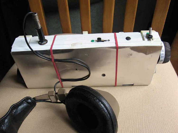
In June this year, with CLE145 coming at the end of July, Max needed to be re-awakened and tested before taking it with us to Scotland. It had always suffered a little from hand capacity effects - touching some parts caused minor changes in frequency, as did the aerial being blown about by strong winds, etc. I discovered that one of my old PC keyboards had a big metalised screen under the keys. This cured all those problems merely by placing it (fixed with rubber bands!) over the front of the receiver. It also stops an occasional 'fizzing' kind of interference if I slide the first few inches of the headphone lead under the rubber band to hold it against the screen (see picture). I assume that problem was caused by some kind of RF getting through to the 'phones.
The attached pictures show Max's front view, the inside view with the back cover unscrewed and the circuit diagram.

In the front view the main tuning knob is at the top right hand side, still with primitive frequency markings on it! (35 = 350 kHz, etc.).
The regen. control is just visible at the bottom left hand side.
The top right hand switch extends the tuning range below 300 kHz by adding the second half of the variable capacitor.
(The top central switch is a refinement that allows the tuning to cover just the Medium Wave broadcast stations by using a different winding).
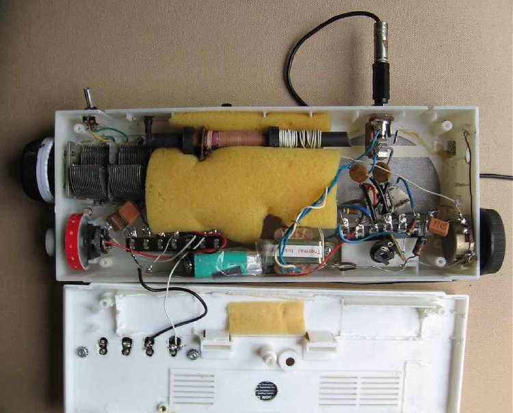
In the inside view, the main components are:
The transistor on its hacked bit of white circuit board which can be seen centre right.
The windings on the ferrite rod at the top are, left to right, the original main tuning coils, aerial coupling and the regen. coil.
The bottom right potentiometer is the regen. control.
The 'floating' pot. is the base bias control.
The large top left knob is main tuning, (I tried adding a fine tuning capacitor in parallel, but it added operating complication without any advantage and I removed it)
The bottom left pot. (still as in the original set) is spare, but it incorporates the battery ON/OFF switch.
The battery, wrapped in plastic in case it shorts things, can be changed using the hinged flap.
(However the battery drain is about 1 mA, so the battery would last for many months if I listened for an hour every day!)
The output matching transformer is next to the battery.
As you can see, my approach has been very 'Heath Robinson' and a real hit-and-miss affair, so don't put much reliance on it. The set does work pretty well, but I'm sure circuit design experts will see lots of things than could be improved - and not just the quality of the soldering! Others are likely to use different transistor types and component values and some connections may be different. A MOSFET would be expected to perform better.
In case you haven't used a regeneration set before, the regen. control allows feedback of some of the RF signal to the main tuning circuit. As the regen. knob is increased from zero it increases the apparent signal strength considerably. Broadcast stations get much louder and a very local NDB would just be heard from its audio ident (a 400 Hz or 1020 Hz Morse tone). Turning the regeneration control up further continues to increase the signal strengths until suddenly beat notes start to be heard when you tune across any carriers. Now you hear the NDB signals much as 'real' receivers would when using their CW setting and no filter (or a very wide one).
The regen. could be increased even further, but eventually the set starts to fizz or wail loudly and becomes a 'dirty' transmitter - not useful!
If you have read as far as this you must have already built a simple set or are at least a bit tempted to!
If you have a little spare time, do give it a try. It really is a fun project and when you start to get results it is like reliving all over again those early days when you were delighted by your first DX loggings - only this is even more satisfying!
I'm grateful to Mike and Finbar for their encouragement and suggestions. I sent details of their sets to the List on 10th June in my email introducing the 'Barn Door CLE145' in late July. It would be good to hear details from any others with working sets or who are well on their way to having them.
Good listening!
Brian
Now if this is something that might interest you, filling a log page of NDBs heard on your own little creation, then there is still plenty of time to whip something together. If you prefer 'modern', then Mike and Brian's circuits might be a good place to begin experimenting or you could just grab one of your old Handbooks and check out the simple regenerative circuits described ... from the '30s on up! Just beef up the L and C values enough to get you down below the broadcast band and you're in business.
There is also a ton of stuff on the web via the vintage magazine and book collection available at the American Radio History website here, with enough info to keep you at the workbench for a long time.
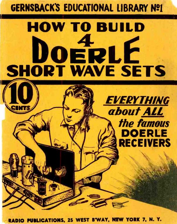 |
| courtesy: American Radio History |
Here is the CLE info, direct from Brian:
Our 233rd Coordinated Listening Event is only just over, but Joachim and I
want to tell you a little about something special coming for our next CLE,
27th - 30th July.
For CLE234 we’ll have one of our occasional ‘Barn Door’ CLEs.
It will be an opportunity to bring back to life basic kinds of receiver -
anything with low selectivity which allows you to hear NDBs on several
frequencies simultaneously – “leaving the barn door wide open!”.
Our last Barn Door CLE was No. 209 in July two years ago.
Listening with 'back to basics' equipment often gives very satisfying and
unexpected results. It can also show us ways of improving our listening
when operating more normally.
To take part, you could use any one of the following:
1. A simple home-made receiver, such as a single transistor set with regen.
(e.g. based on the sets used by Mike Tuggle, Finbar and others).
2. OR - an ultralight receiver (maybe one converted to cover the NDB
frequencies with a modified aerial).
3. OR - an 'antique' receiver brought back to life (e.g. Scott,
Eddystone, R1155, etc.). Most of those are anything but ultralight!
4. OR - a normal receiver but with NO filtering, or using a WIDE FILTER,
(not less than about 2 kHz and with no selection of an audio filter).
Your 'barn door' should be open wide enough for you to hear any NDBs
on at least five adjacent frequencies all at the same time - E.g. NDBs on
348, 349, 350, 351 and 352 kHz with the receiver set to 350 kHz.
Listening to one NDB and ignoring several others of different pitch can be
quite a challenge - but it is very satisfying when you find how quickly it
becomes easier to do.
It may take a while to prepare for some of those ways of listening,
especially the first - hence this ‘Early Warning’!
The attached guide *** (click here) from the past by Mike Tuggle may help you if you are thinking of using a basic D-I-Y receiver.
The ‘Early Advice’ and ‘Final Details’ for the CLE will follow about 9 days
and 6 days before the event, earlier than usual to help you to get ready.
Good Listening!
Brian
-----------------------------------------------------------------
From: Brian Keyte G3SIA ndbcle'at'gmail.com
Location: Surrey, SE England (CLE coordinator)
----------------------------------------------------------------
4 Responses to “Barn Door Wide!”
Please support our generous sponsors who make AmateurRadio.com possible:
 Ham Radio Deluxe |
 W5SWL Electronics |
 Ham Radio Prep |
 KB3IFH QSL Cards  Hip Ham Shirts  HamRadioAuctions HamRadioAuctions Reliance Antennas Reliance Antennas Enigma Shop Enigma Shop |  morseDX  Ni4L Antennas  R&L Electronics R&L Electronics antennas.us antennas.us QRV QRV |
- Matt W1MST, Managing Editor

That sounds like fun! Now I want to build another regen. (As if I didn’t have too many projects already.) I made one for shortwave from a 6SN7 tube for my brother for Christmas about 40 years ago. I almost kept it for myself.
In the CLE announcement, what does it mean by an “ultralight receiver”? Would that be something like a portable transistor radio, like a Sony ICF-7600?
Yes! Any of the small portables that cover the LW band would be good, especially if they have a CW or SSB mode.
This link shows the excitement of ‘ultralight DXing’:
http://peditio.net/utility/docs/ultra.doc
Yes the 7600 would be fine. There are a number of small portables that cover the LW band (for European broadcasters)… even better if the receiver has CW or SSB modes. I had earlier submitted a link to an ‘ultralight’ article but it seems that the link prevented my post from appearing, possibly thinking it was spam.
Sure brings back a lot of pleasant memories from my 1950s & 1960s days—built many tube type regen receivers & also later played around with some Direct Conversion circuits—amazing performance considerng the simplicity design.
I also had a complete set of the small Gernsback’s educational library & just could not do without refering to them almost every day !