Author Archive
 630m Loading Coil & Variometer Update

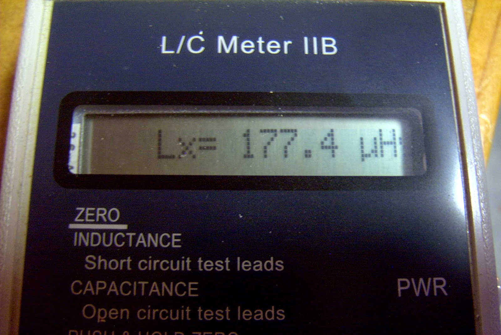
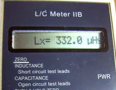
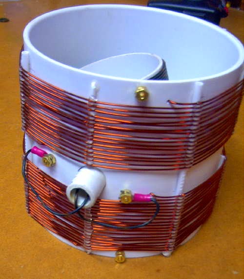
Originally planning for something in the 130-230uH range, the final result produced 177-332uH...certainly more than enough and perhaps a little too much more. I may end up removing a few turns from the main coil as apparently the best variometer efficiency is realised when operated towards the maximum end of inductance, rather than at the low end or when the inner coil is bucking the main coil.

 |
| Source: http://www.alg.myzen.co.uk/radio/136/ant_xformer.htm |
 | ||
| Source: http://www.alg.myzen.co.uk/radio/136/ant_xformer.htm |
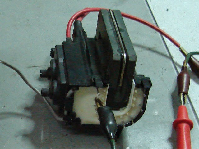 |
| Source: http://leoricksimon.blogspot.ca/2007/05/flyback-driver.html |
Cycle 24 Battles On
 |
| Courtesy: http://www.nasa.gov |
 |
| Courtesy: http://www.nasa.gov |
Video of the event shows what looks like a near full-on earth-directed hit but for a northerly component. Only time will tell.
Sky watchers as well as VHFers should be alert for possibly major auroral displays on Friday or Saturday.
A New 630m Loading Coil & Variometer
I've decided, for the time being, to keep my 2200m (136kHz) antenna tuning system separate from the 630m system. This means that I'll need to build a new loading coil, variometer and impedance matching transformer. I'm not really sure why I should maintain the 2200m capability since there is not really much activity here. The only two excuses that I have at present are the fact that it took a heck of a lot of work to get to this point (but it was mostly "fun work") and that the U.S. may be getting the band soon. I'm also not convinced that even if the U.S. does get the band that it would translate into much new activity....so, for the time being, I will keep the system intact.
I've used an online coil calculator to design the coils needed for loading and for the variometer....it will be interesting to see how close the finished values compare with the calculated values. I hope they're not too far off! Here is what the plan calls for:

The main loading coil will be built on a low-loss 6" styrene pipe coupler using #16 solid copper transformer wire, spaced at 3mm. The coil will be elevated above the main form by strips of styrene rod that I have filed small notches into, every 3mm. The rod height will be staggered around the form, gradually stepping down one full turn every 360 degrees. Inside the main coil, the smaller variometer coil will be wound with poly-covered #18 stranded wire on a short length 3 1/2" PVC pipe.
Hopefully I'll get something that tunes from 130-230uH, approximately....if so, I'll not only be happy, but really surprised!
Perseus Alaskan NDB Watch
 |
| Courtesy: https://www.google.ca/maps/ |
09/09/14 1300 529 SQM Level Island AK CO36
09/09/14 1300 396 CMJ Ketchikan AK CO45
09/09/14 1300 391 EEF Sisters Island AK CO28
09/09/14 1300 372 FPN Fredericks Point AK CO36
09/09/14 1300 266 ICK Annette Island AK CO45
09/09/14 1300 414 IME Mt. Edgecumbe AK CO27
09/09/14 1300 394 RWO Kodiak AK BO37
09/09/14 1300 209 CYT Yakataga AK BP80
09/09/14 1300 390 HBT Sand Point AK AO95
09/09/14 1300 358 SIT Sitka AK CO26
09/09/14 1300 350 VTR McGrath AK BP22
09/09/14 1300 338 CMQ Campbell Lake AK BP41
09/09/14 1300 429 BTS Dillingham AK BO08
09/09/14 1300 233 ALJ Johnstone Point AK BP60
09/09/14 1300 212 CGL Coghlan Island AK CO28
09/09/14 1300 223 AFE Kake AK CO36
09/09/14 1300 229 AKW Klawock AK CO35
09/09/14 1300 283 DUT Dutch Harbor AK AO63
09/09/14 1300 245 HNS Haines AK CO29
09/09/14 1300 347 DJN Delta Junction AK BP74
09/09/14 1300 411 ILI Iliama AK BO29
09/09/14 1300 277 ACE Homer AK BO49
09/09/14 1300 355 AUB King Salmon AK BO18
09/09/14 1300 524 MNL Valdez AK BP61
09/09/14 1300 382 JNR Unalakleet AK AP93
09/09/14 1300 281 CRN Cairn Mountain AK BP21
09/09/14 1300 385 EHM Cape Newenham AK AO88
09/09/14 1300 385 OCC Yakutat AK CO09
09/09/14 1300 263 OAY Norton Bay AK AP84
09/09/14 1300 390 AES Northway AK BP29
09/09/14 1300 404 GCR Cordova AK BP70
09/09/14 1300 525 ICW Nenana AK BP54
09/09/14 1300 251 OSE Bethel AK AP90
09/09/14 1300 341 ELF Cold Bay AK AO85
09/09/14 1300 356 HHM Kotzebue AK AP86
09/09/14 1300 248 GLA Gulkana AK BP72
09/09/14 1300 379 IWW Kenai AK BP40
09/09/14 1300 399 SRI St. George AK AO56
09/09/14 1300 359 ANI Aniak AK BP01
09/09/14 1300 272 UTO Utopia Creek AK BP35
09/09/14 1300 257 CUN Fairbanks AK BP64
09/09/14 1300 227 MHM Minchumina AK BP33
09/09/14 1300 346 OLT Soldotna AK BP40 mod
09/09/14 1300 414 OQK Noatak AK AP87
09/09/14 1300 347 TNC Tin City AK AP65 mod
09/09/14 1300 325 BVK Buckland AK AP95
09/09/14 1300 275 CZF Cape Romanzof AK AP61
Highlighting the morning was my first "new catch" from Alaska in several years - 'SMA' at St. Mary's Lake on 230kHz. It has been on my morning check list for many many years but only today did it decide to reveal itself!
09/09/14 1300 230 SMA St. Mary's AK AP82 USB 231.085 no sign of a LSB
Reported to be running 70 watts, this particular beacon has never been reported to the RNA NDB list nor even heard by those listening in Alaska. I suspect either a very tough path or a system in need of a tune- up. A Google Map view appears to show a single vertical antenna but it may be one end of a 'T' support.
 |
| Courtesy: https://www.google.ca/maps/ |
Hopefully conditions will continue to improve as there are still a few up there that have yet to be logged!
Smoke Testing The GW3UEP 630m Transmitter
 |
| Drain (top) vs Gate (lower) on testbed Class-E GW3UEP TX |
I've just completed the Muppet-styled printed circuit version of my previously breadboarded GW3UEP 630m transmitter. The earlier version was built "ugly style" in order to optimize part values and measure circuit parameters.
 |
| Testbed (Ugly-Style) |
 |
| Final Version (Muppet-Style) |
Running the TX at 12.8VDC on the drain(s) at 2.3A produces an input power of 29W. The measured power out, after the LPF, is 23W into a 50 ohm load. This represents an efficiency of 80%. When run in the normal speed CW mode, the FETs run cool enough that they would probably not even need a heatsink but if run in any of the QRSS (long keydown periods) modes, would certainly benefit from heatsinking.
Running the TX at a higher voltage of 22.6VDC (on the amplifier only) yields a current of 4A for an input of 90W. Measured output power is 71W for an efficiency of 79%.
Heatsinking would be required at this power level, even for normal speed CW but the finals seem to run just slightly warm. A larger heatsink or possibly a small fan as well would be required for any QRSS CW modes.
I suspect that the efficiency could be further improved yet with very fine tweaking of the output circuit L/C network but the extra few watts gained would not be significant.
At either power level, this easy-to-build transmitter would make a great "first 630m transmitter" for anyone wanting to get started on our new band.
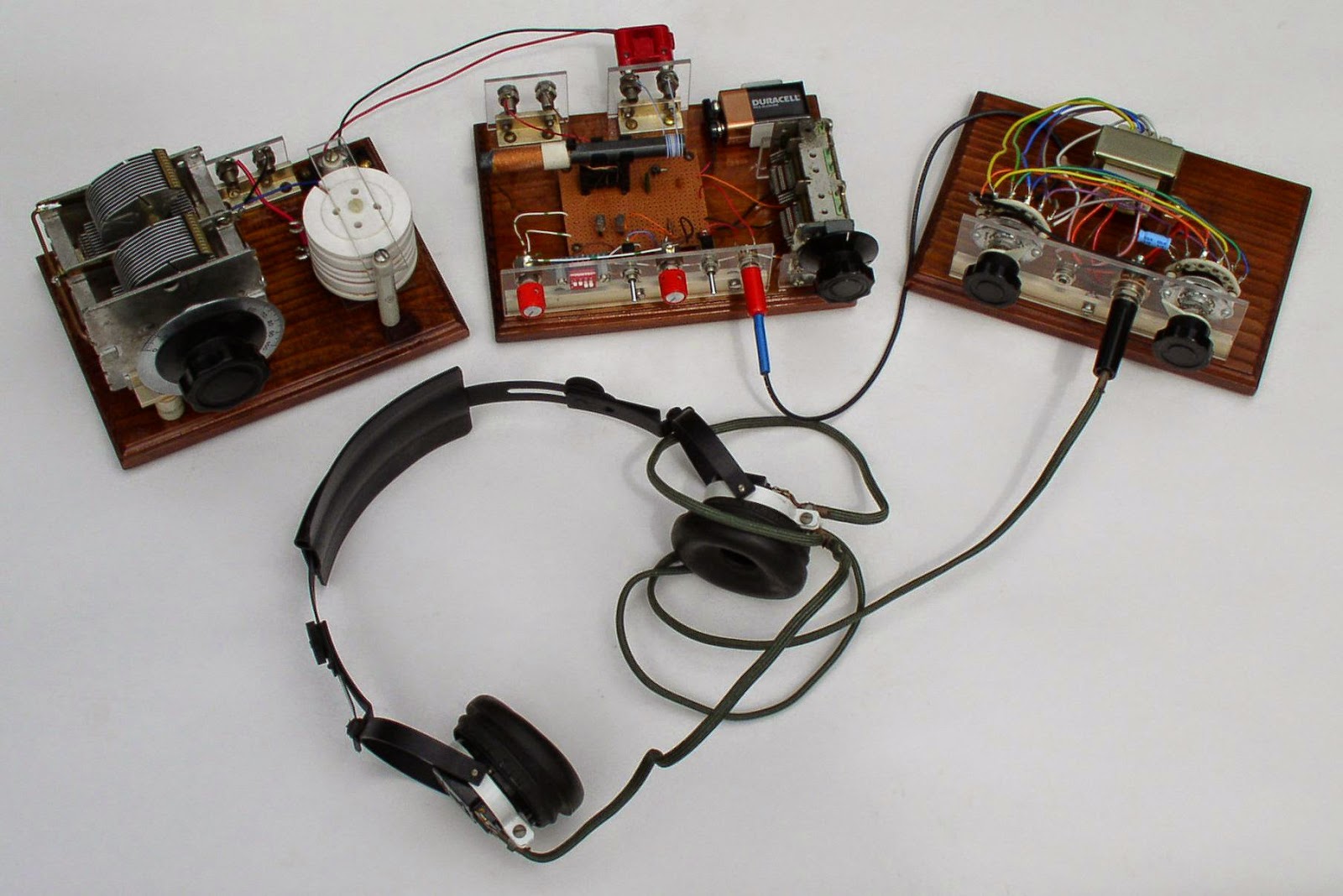
Tuggle-Style LF Regens
 If the name sounds familiar, you may recognize it from reading about the DX crystal radios that Mike Tuggle has created over the past several years. Some might even say that his state-of-the-art and very elegant "Lyonodyne 17" crystal radio re-kindled the modern day interest in crystal radio DXing, once the mainstay of all radio adventures.
 |
| Mike Tuggle's Lyonodyne 17 Crystal DX Tuner |
I'm not sure what sparked Mike's interest in building regens but it may go back several years to the "1AD" contest sponsored by the Birmingham Crystal Radio Group. This was a DX contest challenge that allowed a receiver to use only "1 Active Device", as explained in the rules:
"Only one active device is allowed to be counted to get the 1AD bonus points. The device can be a bipolar, FET, tunnel diode or tube (triode, tetrode, pentode, or heptode), but only one device may be used. If a tube envelope has more than one tube in it, use only one of those active devices to be counted as a 1AD. Crystal sets may be used if one active device is added either inboard or outboard. Totally passive crystal sets are not allowed. In the active set, any number of diodes (either solid state or tube diodes) may be used; however, a tunnel diode or similar active device counts as the 1AD for the contest.
The use of integrated circuits can be interesting in that one IC can be used to build a full superhet. The use of an IC means that the set will not qualify for the 1AD nor for the 2AD bonus points."The challenge was too hard to resist for many and the contest was popular for several years running. Some of the inventive entries for individual years may be seen here. The contest logbooks also make for interesting reading and demonstrate the capability of some of these simple radios.
Although the contest has not been run for the past few years, there is still much interest and discussion of "1AD" radios on Dave Schmarder's "RadioBoard" forum.
Mike's LF tuner is a prime example as he uses it daily and continues to post some amazing DX to the Yahoo "ndblist" Group. His furthest ndb catch in North America with the regen has been "YY" in Mont Joli, Quebec.
Now, "YY" is a good catch for me, from B.C., but Mike is listening from Kaneohe, Hawaii !
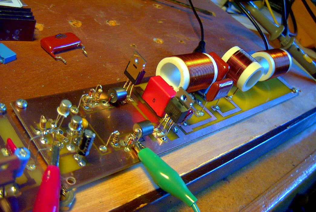
You can read about Mike's original design here, while his latest version shown below, incorporates a dedicated LF antenna tuner.
 |
| LF Regen (Courtesy Mike Tuggle) |
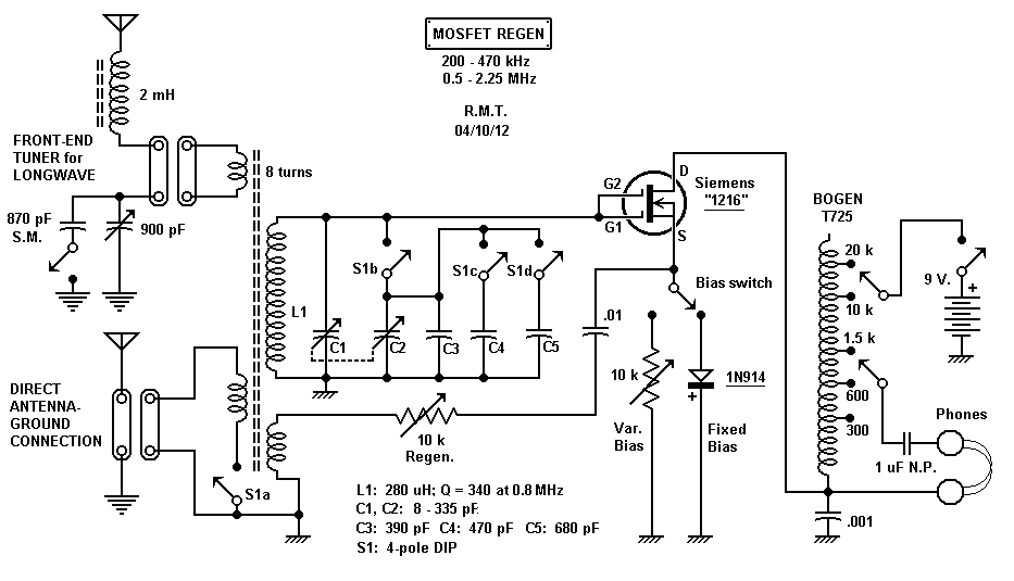 |
| LF Regen Schematic (courtesy Mike Tuggle) |
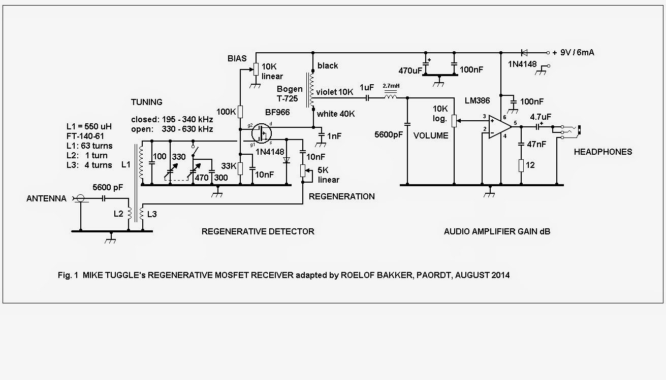 |
| Courtesy: Roelof Bakker, PAØRDT |
Roelof has also published a nice write-up describing the project which sparked a lot of "must build" discussion within the group.....even enough to make Mike get out his soldering iron and build the European-version!
As old and as simple as they are, regenerative receivers still hold much fascination amongst radio builders and dollar-for-dollar are amazingly good performers, especially on LF.
630m Trans-Pacific Path Heats Up!
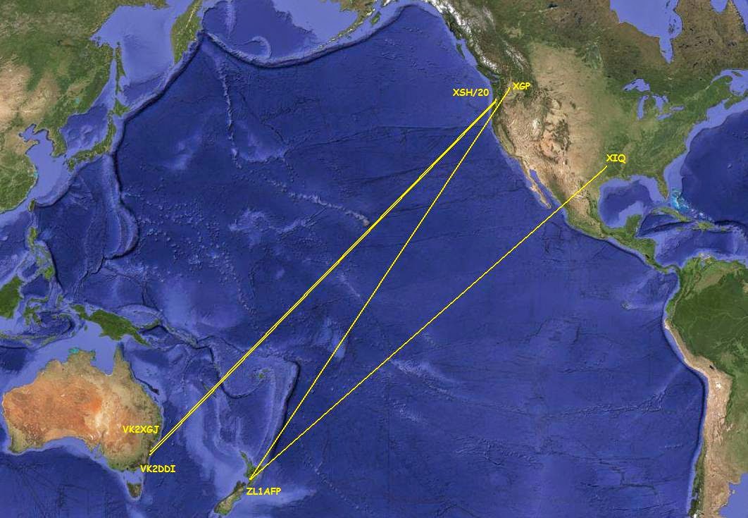 |
| Courtesy: https://maps.google.ca/ |
Once again, John ("XIQ"), was heard on the other end....not in Australia but in New Zealand, by Con (ZL2AFP) listening in residential Wellington. Con also caught signals from Larry, W7IUV, in central Washington state, operating on 630m as WH2XGP. Not to be left out of the action, Rudy, N6LF, running as WD2XSH/20 made it down to both VK2XGJ and VK2DDI before the sun came up south of Eugene, Oregon.
Larry, W7IUV ("XGP"), was running a true backyard-size antenna system...just a 34' loaded vertical with a sloping zig-zag top loading wire. His small wire radial system covers a 16' x 25' patch. His homebrew amplifier, constructed almost exclusively from salvaged computer parts, uses 8 switching MOSFETs in push-pull / parallel running in the rare linear mode! The fascinating description of his amplifier's design and construction can be found at the W7IUV website. With the small vertical, estimated erp is ~ 10 watts.
Larry's station should be inspirational for anyone who thinks they need huge antennas to be successful on 630m!
Rudy, N6LF ("XSH/20"), runs around 20Weirp to a large top-loaded vertical. The center (radiator) pole is almost 100' high while the top-loading support poles are 80'. Full details of Rudy's fine system, along with much more about 630m, may be found at the Antennas By N6LF website.
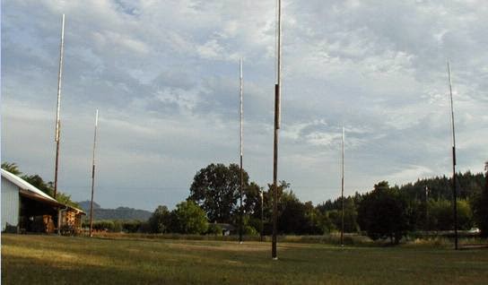 |
| N6LF/WD2XSH/20 630m Top-Loaded Vertical |
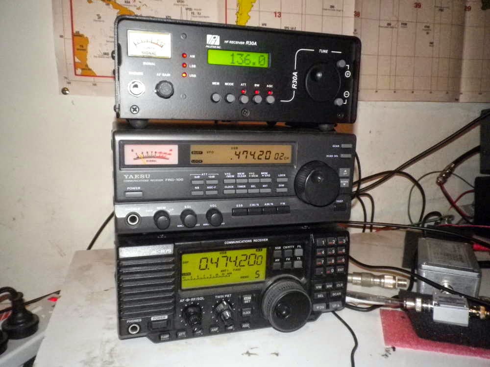 |
| LF RX Stack at VK2XGJ |
Hopefully conditions will continue to provide more long-haul reports in the coming weeks.
In the meantime, remember that Canadian amateurs now have free access to the 630m band, but much more activity is needed...VE6, VE5, VE4, VE3, VE2...who will be the first on 630m in those provinces? It's time to start melting solder and stringing antennas before winter arrives!


