Author Archive
 Portable Lightwave Receiver Progress
Yesterday, between dabbling in the Arkansas State QSO Party on CW, I manufactured and assembled the PCB for the new 'portable' lightwave receiver. When building PCBs, I use the printer-toner method, after drawing the design with MS Paint. Compared to some of the freeware PCB design software now available it is fairly crude, but it more than meets my needs and could even work for designing SMD boards if needed. I've also made the switch from using the messy and corrosive Ferric Chloride etchant to a weak solution of Hydrogen Peroxide and Muriatic acid. The latter seems so much cleaner, faster and overall produces a better-etched board. Boards can be completely etched in around three minutes, compared to the much longer Ferric Chloride.
I chose to use the same receiver circuit as the one in my main system, garnered from the design shown in Roger's, (G3XBM) blog. If you have an interest in getting started in lightwave experimenting, you will find Roger's blog of his lightwave adventures to be both informative and inspiring.
 |
| courtesy: http://g3xbm-qrp.blogspot.ca |
As before, I made a couple of minor changes to the receiver, substituting a BPW34 optical pin diode for the one shown as well as subbing a 2N5457 JFET for the MPF102. In addition, 2N5089s were substituted for the 2N3904s. The newer JFET is lower in noise as are the higher gain 5089s. In all likelihood, the differences are only minor but I like to think that every little bit helps when all system-losses are considered.
Note that it is important to make the connection between the diode and the JFET's gate lead 'floating' in the air as any contact with the PCB could introduce unwanted loses at this point.
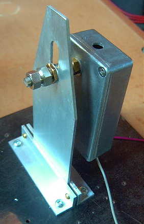
As in my original receiver, a locking split-shaft, removed from a junk box potentiometer, was mounted to the back side of receiver box. This will allow the receiver box and its pin-diode to be aligned forward and backward for focus and then locked. Once built, the focusing carriage will allow the receiver to move laterally, left to right as well as vertically, up and down. Positioning the optical diode at the exact focal point of the lens and maintaining this position is crucial. The finished carriage, will look similar to this one, used in my main system's receiver and transmitter box.
So it's on to the plywood receiver box and then the focusing carriage. It will be interesting to see how my $5 fresnel lens page-reader, purchased from Princess Auto, compares with the slightly larger (and probably better) lens in the main system's receiver.
Quiet Sun Not Enough
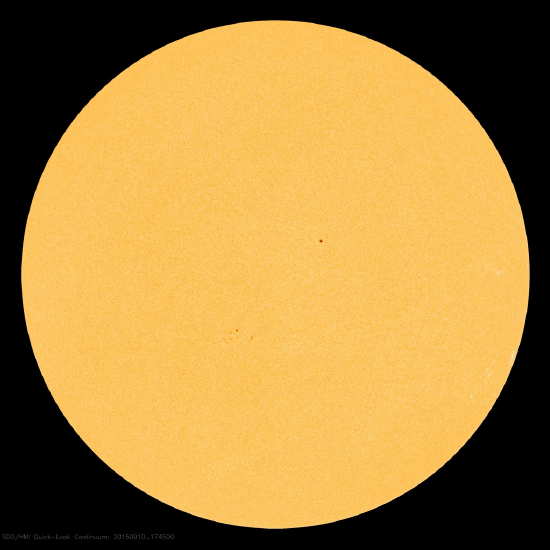 |
| courtesy: http://sdo.gsfc.nasa.gov/ |
... the sun has been deathly quiet, as can be seen in yesterday's solar disk image.
It seems that just the 'normal' solar wind can disrupt things all on its own, without any solar flares or coronal mass ejections. In the late 70's, 'cracks' in the earth's magnetosphere were first observed... cracks that allowed even a quiet solar wind to actively interact with the earth's (normally protected) upper atmosphere. Apparently this is the present condition that has been disrupting normal propagation for the past many days.
The spaceweather.com web site has a nice explanation of how these cracks allow the Sun's Interplanetary Magnetic Field (IMF) to interact with the earth's field:
"Earth has a magnetic field, too. It forms a bubble around our planet called the magnetosphere, which deflects solar wind gusts. (Mars, which does not have a protective magnetosphere, has lost much of its atmosphere as a result of solar wind erosion.) Earth's magnetic field and the IMF come into contact at the magnetopause: a place where the magnetosphere meets the solar wind. Earth's magnetic field points north at the magnetopause. If the IMF points south -- a condition scientists call "southward Bz" -- then the IMF can partially cancel Earth's magnetic field at the point of contact.
When Bz is south, that is, opposite Earth's magnetic field, the two fields link up," explains Christopher Russell, a Professor of Geophysics and Space Physics at UCLA. "You can then follow a field line from Earth directly into the solar wind" -- or from the solar wind to Earth. South-pointing Bz's open a door through which energy from the solar wind can reach Earth's atmosphere!"
Earth's Bz has been pointing south during this entire period of poor propagation. Heavy ionization of the daylight D-layer, normally an 'absorber' of LF signals, has allowed reception of several NDB signals normally only heard at night. In fact, one of my favorite NDB propagation indicators, 25-watt YLJ in Meadow Lake, Saskatchewan, has been heard all day long on 406KHz for the past week as its signal skirts along the underside of the dense D-layer. These auroral conditions however, often enhance the path to the south Pacific and several western BCB DXers have reported excellent propagation to Australia and New Zealand in the pre-dawn hours.
Another indicator of LF propagation disturbance is the DST or Disturbance Storm Time index. This number gives an indication of the severity of the weakness in the magnetosphere, with numbers going further and further negative as the charged particles trapped in the magnetosphere increase in numbers.
 |
| courtesy:http://wdc.kugi.kyoto-u.ac.jp/dst_realtime/presentmonth/index.html |
The DST has been having a rough ride since the beginning of the month and as these numbers grow more positive and remain there, propagation will return to normal. With late September and October often being among the best months of the year for LF propagation, and with the sun now doing its part by remaining quiet, let's hope that the earth's magnetosphere will also co-operate and seal-up those propagation-killing cracks.
New Lightwave Modulator
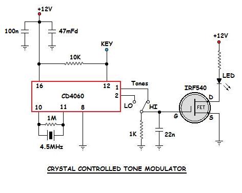
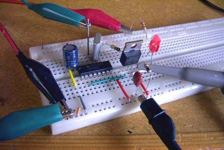
 Yesterday I completed the construction of the crystal-controlled tone generator which will be used to modulate my lightwave transmitter during future clear-air / cloudbounce tests.
 It was installed on the lightbox, right beside the original 556 CW beacon / tone generator.


The crystal-controlled oscillator uses a CD4060 IC as an oscillator-divider and produces a ~550Hz or a ~1098Hz squarewave from the 4.5MHz crystal.
 |
| 4500KHz xtal divided by 8192 showing 549Hz output |
As can be seen by comparing the two oscillators (crystal on the left and 556 on the right), the 556 has a lot of drift (although it looks like it might eventually stabilize) and, as well, produces several spurious signals ... probably robbing power from the main tone. The crystal-controlled signal is rock solid and doesn't appear to generate any parasitic signals in the process. The trace below the crystal signal is unrelated to the oscillator.
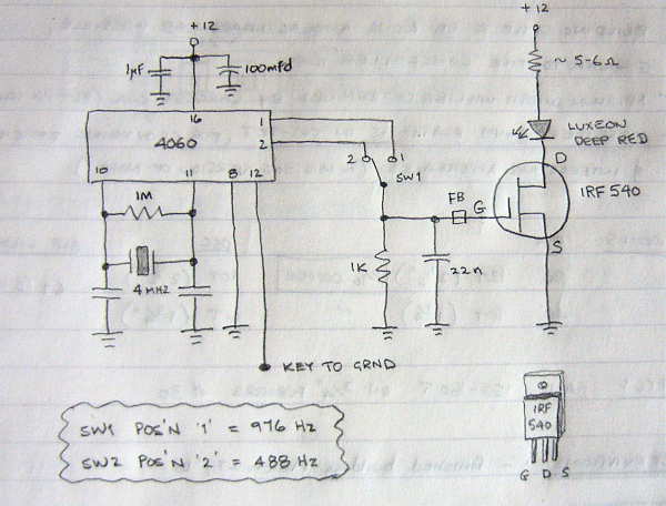
When I first wired the unit up, I found an unstable low frequency oscillation from the 4060 during key-up conditions, due no doubt, to the lengthy leads inside the box. This was cured by adding a pull-up resistor to the keying line as shown in the final schematic below.
Now it's on to building another fresnel-lens receiver box which will be needed for any field work here on the island.
State QSO Parties
 I spent a couple of hours again this weekend playing with the N1MM contest logging software and getting back into the contesting groove. My new K1EL USB interface continues to work flawlessly, even on my ancient XP laptop ... gone are the occasional keying stutters produced when previously keying from the serial port. N1MM is one of the most widely-used contest loggers and is freely available for download here. I still run the older 'Classic' version as I don't think my laptop could handle the newer 'N1MM +' edition ... I'll upgrade when I get a newer contesting laptop.
Both the Colorado and the Tennessee State QSO Parties were held this weekend, providing me another round of CW contest practice. Both activities are pretty low-key affairs when it comes to contesting but hey, every bit of practice helps.
I found surprisingly little action in the CO Party, making just 18 contacts ... 12 on 20m CW and 6 on 40m, with 17 sections worked. There seemed to be more activity from TN amateurs though, with 38 QSO's in 33 sections, 28 on 20m and 10 on 40m. All contacts were made on CW. All of the 40m contacts were made several hours before local sunset here, surprising the heck out of me that the W4's could even hear me in broad daylight ... the stations worked must have very quiet locations.
The state QSO parties are a good way to enjoy a short round of contesting without blowing an entire weekend, which I don't think I would really like to endure, and there seems to be at least one or two of them each weekend ... an easy way to ease into contesting or to keep up your on-the-fly contest keyboarding skills.
LF/MF Moving Closer For U.S. Amateurs
With all commentary periods for the FCC's 'Notice of Proposed Rulemaking' (Docket 15-99) now closed, it appears that one of the last comments to be filed may contain the most powerful arguments in favor of swift implementation.
In its extremely detailed 42-paged submission, the ARRL states, in no uncertain terms, the reasons why access to both the 2200m LF band and the 630m MF band should not be held back and that service rules should be 'finalized'. Indeed the powerful arguments stated in favor of implementation should go a long way in making this happen sooner rather than later.
The FCC's position is that there is little to no evidence to indicate that amateur radio operation on either band would be incompatible with power company PLC systems, going as far as stating that at distances of 1km or more from PLC lines, "there is no chance of interference". Further supporting their claim, the thousands of hours of experimental operation were offered as powerful proof and that the ARRL was “unaware of any reports of interference to PLC systems arising from that operation conducted pursuant to numerous Part 5 experimental licenses…in the large band utilized by PLCs.”
In addition, the ARRL had harsh words regarding the FCC's attempt to legitimize the growing number of fish-net beacons in the 160m band, and pulled no punches regarding their position in this matter.
"There is no indication that these buoys are compatible with other uses in the band, no track record of interference avoidance or resolution, and certainly no indication that the current operators can be relied on for compliance with the Commission’s rules."
"The Commission is urged to avoid enacting rules that it has no effective ability or intention to enforce. That fishing vessels have, with impunity, illegally deployed radio buoys in this band on a widespread basis (whether or not due to misrepresentations of the importers and retailers of these devices or due to a disregard of the Commission’s rules generally) without even nominal enforcement actions by the Commission, provides no basis for assuming that there will be compliance with any deployment limitations (including geographic deployment restrictions) on these buoys going forward. Nor is there any basis for the assumption that there will be any enforcement action taken with respect to continued illegal operation of the buoys if and when interference is caused. Spectrum planning by the Commission in this context has to be based on ex ante determinations of compatibility rather than mere assumptions, especially where the record indicates such a low level of historical compliance."
A summary of the comments can be read here in the ARRL News while all comments filed for the NPRM be found here temporarily, while the FCC site is down for maintenance.
Army-Navy Crossband
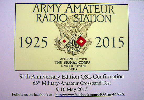
Yesterday's mail brought an official - looking envelope from the U.S. Army! It contained a very nice letter from Fort Huachuca, Arizona, thanking me for participating in the '66th Military-Amateur Crossband Test' as well as three QSL's for the Army-affiliated contacts that I had made back in May.
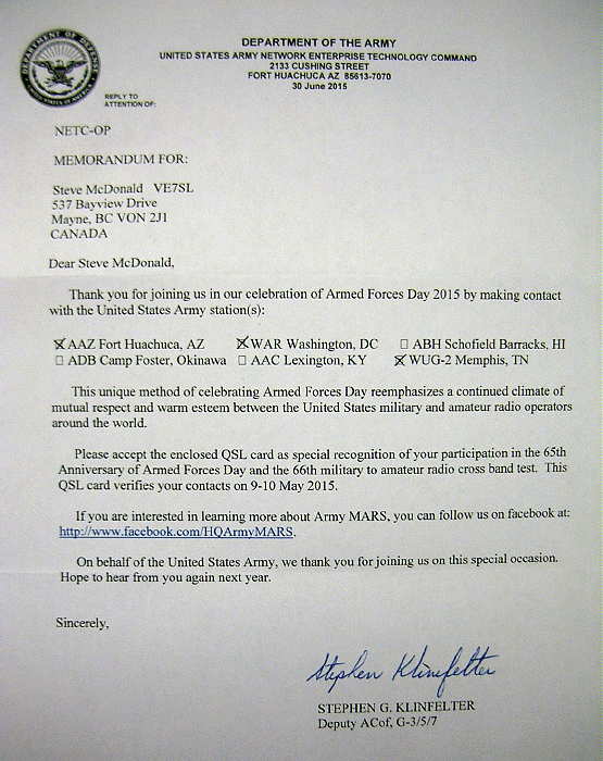
During the activity, I was able to work Army stations AAZ (AZ), WAR (Pentagon), WUG-2 (TN) ... all on 20m via the crossband mode as the military stations transmitted outside of the band.
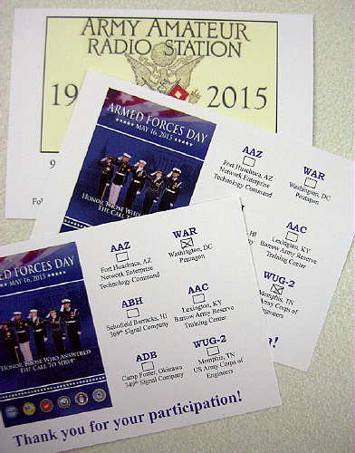
In addition to these three, two Navy stations were worked ... NWVC (IN) and NPD (TN) but it appears that 'Army' has beaten 'Navy' ... at least when it comes to QSL'ing!
Lightwave Scatter
As it is at present, the modulator consists of a 556 tone generator, capable of either a steady tone for CW keying or a two-tone FSK 'beaconing' signal used to help the other station in aiming alignment.
For the slow QRSS CW narrow-bandwidth modes required for the scatter tests, I've always known that a tone which is much more stable and of precisely known frequency would be needed. The tone from the 556 does well as an aural CW keyed tone but would probably be all over the place when viewed in a very narrow-bandwidth and not nearly as stable as it sounds by ear.
The little modulator uses a 4500 KHz crystal (pulled from a old VCR several years ago) in a 4060 oscillator-divider. In this case, output from the chip is taken from either the 'divide-by-8192' pin 2, which outputs a precise frequency of 549 Hz or from the 'divide-by-4096' pin 1, which outputs a frequency of 1099Hz.
 |
| courtesy G3XBM: http://g3xbm-qrp.blogspot.ca/search/label/nlos |
This tone is then used to drive an IRF 540 power MOSFET which controls current through the 1W Luxeon Deep Red LED in the transmitter. The 4060 modulator will be keyed via a QRSS software keying program that I have used for many years to key my LF transmitter.
The lightwave receiving station will look for the QRSS audio signal with an audio spectrum viewer such as Argo or Spectran. The ability to make automatic overnight screen captures will allow the receiving operator to get a good night's sleep while the system diligently watches for any traces of a signal.
An example of a strong signal capture showing a repeating "SL" identification is shown below, as it would appear in a perfect world. In this case (QRSS3), the short 'dots' are 3 seconds long while the 'dashes' are 9 seconds.
Huge signal gains (the ability to dig into the noise for signals) can be had by slowing things down and using narrower receiving bandwidths. Just going from a normal 12WPM speed CW (aural copy) to QRSS3 yields a gain of ~15db. At QRSS10 (10 second dots), an additional 5db is gained while slowing to QRSS60 (60 second dots), a whopping 28 db over 12WPM CW is gained!
Of course all of this extra 'hearing power' comes at a cost and in this case, the cost is 'time'. On an overnight of automated computer monitoring, time is not much of an issue ... it only becomes critical in 'QSO mode' when some QRSS QSOs can take several hours to complete. In any case, it will be interesting to see if any traces of lightwave signals will show up while bouncing around in the clouds.
The Georgia Strait scatter tests will not take place for some time but in the meantime, I hope to do some local tests here, from one side of my island to the other but will build a new portable receiver for these tests and leave my main system intact.


