Author Archive
 Hunting For NDBs In CLE218
 |
| 'XX-344' - Abbotsford, BC |
This coming weekend will see another CLE challenge. This time the hunting grounds will be: 335.0 - 349.9 kHz.
For those unfamiliar with this monthly activity, a 'CLE' is a 'Co-ordinated Listening Event', as NDB DXers around the world focus their listening time on one small slice of the NDB spectrum.
A nice challenge in this one is to hear the Abbotsford NDB, 'XX', on 344 kHz. 'XX' is located about 40 miles east of Vancouver International (YVR) and a few miles SW of the Abbotsford Airport, YVR's alternate for those foggy winter nights. 'XX' is a 500-watter and is well heard, having been logged from the east coast to Hawaii and is a good propagation indicator for listeners in eastern North America. Look for 'XX' on 344.404 kHz with your receiver in the CW mode.
When tuning for NDBs, put your receiver in the CW mode and listen for the NDB's CW identifier, repeated every few seconds. With your receiver in the CW mode, listen for U.S. NDB identifiers approximately 1 kHz higher or lower than the published transmitted frequency since these beacons are tone-modulated with a 1020 Hz tone approximately.
For example, 'AA' in Fargo, MN, transmits on 365 kHz and its upper sideband CW identifier is tuned at 366.025 kHz while its lower sideband CW ident can be tuned at 363.946 kHz. Its USB tone is actually 1025 Hz while its LSB tone is 1054 Hz.
Often, one sideband will be much stronger than the other so if you don't hear the first one, try listening on the other sideband.
Canadian NDBs normally have an USB tone only, usually very close to 400 Hz. They also have a long dash (keydown) following the CW identifier.
All NDBs heard in North America will be listed in the RNA database (updated daily) while those heard in Europe may be found in the REU database. Beacons heard outside of these regions will be found in the RWW database.
From CLE organizer Brian Keyte, G3SIA, comes the usual 'heads-up':
Hello all
Our 218th Co-ordinated Listening Event is less than a week away.
Just a normal CLE using a busy range of frequencies which usually attracts a lot of interest.
First-timers' CLE logs will also be very welcome, as always.
Days: Friday 21 April - Monday 24 April
Times: Start and end at midday, your LOCAL time
Range: 335.0 - 349.9 kHz
Please join us wherever you are - just log the NDBs you can identify
having their nominal frequencies in the range (it includes 335 kHz
but not 350 kHz) and any UNIDs that you come across there too.
We last concentrated on these frequencies for CLE200 in Nov. 2015
when 55 of us joined in.
73
Brian
----------------------------------------------------------
From: Brian Keyte G3SIA ndbcle'at'gmail.com
Location: Surrey, SE England (CLE coordinator)
----------------------------------------------------------
(Reminder: You could use any one remote receiver for your loggings,
stating its location and owner - with their permission if required.
A remote listener may NOT also use another receiver, whether local or
remote, to obtain further loggings for the same CLE).
These listening events serve several purposes. They:
- determine, worldwide, which beacons are actually in service and on-the-air so the online database can be kept up-to-date
- determine, worldwide, which beacons are out-of-service or have gone silent since the last CLE covering this range
- will indicate the state of propagation conditions at the various participant locations
- will give you an indication of how well your LF/MF receiving system is working
- give participants a fun yet challenging activity to keep their listening skills honed
Final details can be found at the NDB List website, and worldwide results, for every participant, will be posted there a few days after the event. If you are a member of the ndblist Group, results will also be e-mailed and posted there.
The very active Yahoo ndblist Group is a great place to learn more about the 'Art of NDB DXing' or to meet other listeners in your region. There is a lot of good information available there and new members are always very welcome. As well, you can follow the results of other CLE participants from night to night as propagation is always an active topic of discussion.
If you are contemplating getting started on 630m, listening for NDBs is an excellent way to test out your receive capabilities as there are several NDBs located near this part of the spectrum.
You need not be an ndblist member to participate in the CLEs and all reports, no matter how small, are of much value to the organizers.
'First-time' logs are always VERY welcome!
Reports may be sent to the ndblist or e-mailed to either myself or CLE co-ordinator, Brian Keyte (G3SIA), whose address appears above.
Please ... give the CLE a try ... then let us know what NDB's can be heard from your location! Your report can then be added to the worldwide database to help keep it up-to-date.
Good hunting!
The JK BevFlex-4 Antenna
This past week, comments regarding an interesting new low-noise directionally-switched receive antenna popped-up on both the Topband reflector and the IRCA (BCB DXers) reflector.
The new JK BevFlex-4 is reported to work very well without requiring a lot of real estate for deployment. The antenna was designed by Geoff Mendenhall, W8GNM, and Ned Mountain, WC4X.
There are several things that make this package a little different. The antenna can be configured in four basic forms: CLASSIC BEVERAGE, BEVERAGE ON GROUND (BOG) / BEVERAGE IN SOD (BIS), INVERTED EWE, or as a FLAG. What is quite different however is its flexible feedpoint allowing the antenna to be fed at any point along its length when used in the BOG or BEVERAGE configuration. The antenna is completely passive and requires no preamplification although, in some configurations, it is suggested for use above 7MHz.
Full details can be found at the JK Antennas website, as well as the manual and a FAQ page.
The FAQ sheet indicates that it will perform from LW through to 10m but the most dramatic improvement in reception from users has been noted on the lower bands. It sounds like it might make an interesting antenna for NDB DXing as well.
In the BOG form, the antenna can lay right on the ground or be buried (BIS) just below the surface using RG-6 for the actual antenna element. Other configurations allow much smaller, stealth-sized wire to be employed.
An interesting YouTube video of the antenna in action as well as an in-depth description may be viewed here:
Here is one comment from an east coast topbander:
I also bought one this year....deployed it as an EWE, as that’s all the room
I have, small lot in a subdivision.....in order to work them you need to
hear them, and once I put that up, I could hear !!! first put up as EU/VK-ZL
and worked several in the DX contest, but when the african dxpedetions were on, moved it to due east/west., and worked all of them, S01, etc.....front to back is remarkable on 160, it works ok on 80, (mine was 10ft high and 38 ft long) but really rocks on 160 !!!!, and really cuts down the line noise/static I normally hear on my transmit Inv L.
Perhaps this may be your answer for a small effective receive antenna for LW and above but even if not, their website description makes for interesting reading.
April Moonbounce
 |
| My Moonrise |
This week I had several days of unobstructed ocean moonrises as the Moon peaked on its monthly northern declination track. Thanks to the recent topping of my next door neighbour's large Douglas Fir, and removal of low-hanging branches, I am now able to track moonrises a little further to the south than before and can add two more EME days that were previously blocked by the large tree. All operations are on 2m JT65B mode, using a 9el Yagi and 140W output.
When I started (April 1) conditions looked as if they should be good, with lunar perigee (Moon's closest approach), degradation (background skynoise) and declination all looking favorable, but I was in for a surprise.
The rising yellow plot indicates the Earth-Moon distance growing further apart (increasing path losses) while the red plot indicates fluctuation in daily skynoise (temperature) near the moon. The blue plot indicates declination track from north to south ... for me, the higher the better.
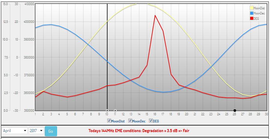 |
| courtesy: http://www.mmmonvhf.de/eme.php |
On day three, five new 'initials' were worked including one new state (New York) and two new DXCC countries! Truly surprising was that two of the stations worked were using just two Yagis, with both stations answering one of my 'CQ's.
Good conditions continued for the next few days, bringing my initials count from #87 to # 95, with the following stations all going into the log, turning a disappointing start into one of the best lunar sessions I have encountered:
HA6NQ, LZ2FO (two 13 el Yagis), EB5EEO, K2ZJ (two 14 el Yagis), DK5YA, S52LM, F8DO, PA5Y, SV6KRW, UA3PTW, OK1UGA.
April's operation brought my 2m DXCC count to 29 and states worked total to 27.
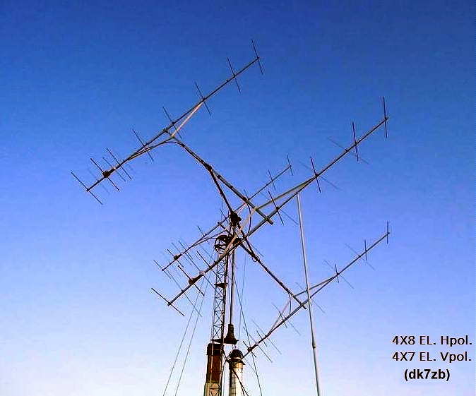 |
| SV6KRW's 4 x 8el Array |
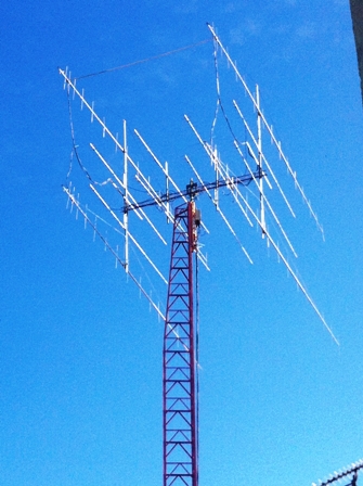 |
| EB5EEO's 4 x 32el Cross-polarized Array (16V / 16H) |
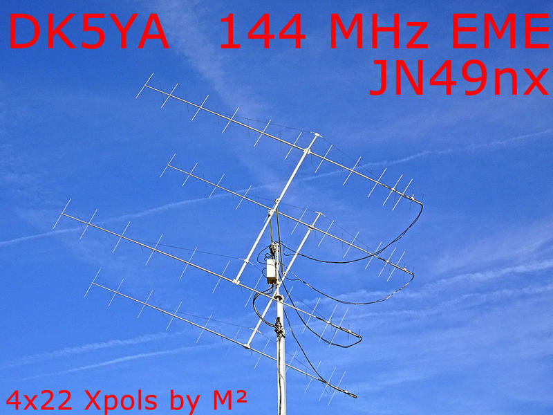 |
| DK5YA's 4 x 22 Cross-polarized Array (11V / 11H) |
April Moonbounce
|
| My Moonrise |
This week I had several days of unobstructed ocean moonrises as the Moon peaked on its monthly northern declination track. Thanks to the recent topping of my next door neighbour's large Douglas Fir, and removal of low-hanging branches, I am now able to track moonrises a little further to the south than before and can add two more EME days that were previously blocked by the large tree. All operations are on 2m JT65B mode, using a 9el Yagi and 140W output.
When I started (April 1) conditions looked as if they should be good, with lunar perigee (Moon's closest approach), degradation (background skynoise) and declination all looking favorable, but I was in for a surprise.
The rising yellow plot indicates the Earth-Moon distance growing further apart (increasing path losses) while the red plot indicates fluctuation in daily skynoise (temperature) near the moon. The blue plot indicates declination track from north to south ... for me, the higher the better.
|
| courtesy: http://www.mmmonvhf.de/eme.php |
On day three, five new 'initials' were worked including one new state (New York) and two new DXCC countries! Truly surprising was that two of the stations worked were using just two Yagis, with both stations answering one of my 'CQ's.
Good conditions continued for the next few days, bringing my initials count from #87 to # 95, with the following stations all going into the log, turning a disappointing start into one of the best lunar sessions I have encountered:
HA6NQ, LZ2FO (two 13 el Yagis), EB5EEO, K2ZJ (two 14 el Yagis), DK5YA, S52LM, F8DO, PA5Y, SV6KRW, UA3PTW, OK1UGA.
April's operation brought my 2m DXCC count to 29 and states worked total to 27.
|
| SV6KRW's 4 x 8el Array |
|
| EB5EEO's 4 x 32el Cross-polarized Array (16V / 16H) |
|
| DK5YA's 4 x 22 Cross-polarized Array (11V / 11H) |
The Artwork Of DK1IS
Recent discussion on the RSGB LF Group reflector about high-powered LF / MF amplifiers brought an interesting response from Tom, DK1IS, and his unique solution.
It's no secret that a Class D / E amplifier using switching MOSFETs is a popular and reasonably inexpensive method of generating some serious RF on the LF and MF bands. Equally well-known is their propensity to gobble-up FETs should the amplifiers encounter much reactance in their output load. Most builders include some form of protection for sudden over-current or unwanted SWR excursions which will shut down the amplifier before any FETs can self-destruct. Those that don't usually end up replacing FETs.
I would venture to guess that over 90% of the transmitters now being employed on LF or MF are using switching MOSFETs in a Class D / E design but there are some amateurs using vacuum tubes to do their heavy-lifting ... and with good results.
DK1IS's beautiful homebrew amplifier is shown below. Tom provided the following description:
Hi Wolf and group,
nice to hear that someone else is thinking about this approach! I´m
content with my homemade tube PA for LF and MF which has provided
reliable service since nearly 4 years now. Only some thoughts about this
concept - I hope not to bore all those hams who are happy with their
semiconductor PAs:
Years ago I had a MOSFET PA for LF, Class B push-pull with 250 W RF. It
worked well at constant conditions, but when I had to retune the antenna
due to larger QSY or made antenna experiments there always was the
danger of blowing up these nervous semiconductors. After 4 or 5 times
changing the MOSFETS I decided to build a new PA - with tubes! Looking a
little bit anachronistic this PA is absolutely good-natured. Designed for
broadband service on LF and MF it makes no problems when changing the
antenna coarse tuning from one band to the other even when the fine
tuning isn't done yet. With my former MOSFET-PA this would have been
impossible.
I wanted to have a linear PA - this usually means class B. You have to
decide between narrow band and broad band (like an audio-amp) design.
For narrow band you can use a single-ended PA but you have to add a
resonance circuit. For broad band you should use a push-pull PA and have
to build a suitable output transformer. I opted for broad band design
because it is usable for LF and MF without changes at the PA. With this
design and sin-driving I reach a total harmonic distortion of about 5 %
at 700 W RF on a pure resistive dummy load. With the usual narrow,
narrow band antennas on LF and MF you don´t need additional filters!
Concerning the tubes: If you take the common TX tubes with plate
voltages of several kV all output circuits have rather high impedances,
that means large coils for the resonance circuits resp. large
transformer windings and very high voltages - potentially a construction
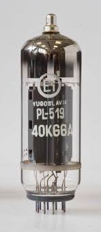
problem. This led me to the choice of 2x 4x PL519 in push-pull, a rugged
colour TV line output tube with low plate voltage and high plate
current. In this way I came down to a plate-to-plate resistance of about
1 kOhm at 600 V DC plate voltage, where you easily can build a ferrite
broad band output transformer down to 50 Ohms. A disadvantage of this
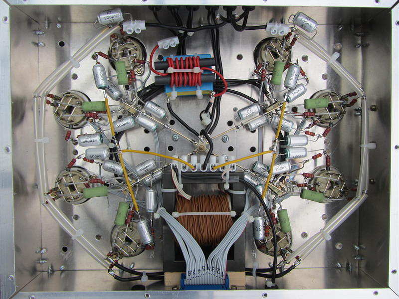
concept is that you have to give individual bias to each tube, that
means for the first start-up you have to align 8 potentiometers
carefully to nearly equal cathode currents for all the tubes. But
according to my experience this alignment remains stable over a long
time. I have inserted 1-Ohm-resistors in each cathode line and have
brought the voltage drops to 8 cinch connectors, where I can monitor the
DC component (with external filtering) as well as the real time current.
With 4 tubes in parallel per branch of course you have to take care for
self oscillations. The extensive use of bypass capacitors, ferrite beads
and parasitic chokes in the plate lines is mandatory as well as good
grounding concepts are. The tubes don´t pull control grid current (this
would even be true in class C!) but you need 3 or 4 W RF input power due
to all the ohmic loads at the tube´s control grids caused by the
individual bias paths. On the other hand this certainly helps to avoid
oscillations. You can see some pictures of this PA at https://www.qrz.com/db/DK1IS
By the way: why not to try these tubes at class D? With DC plate
voltages of perhaps 1200 V you should get a nice QRO-PA ...
Wolf, you are right: building such a PA from scratch is a time consuming
enterprise. I didn´t count the working hours but according to my lab log
the whole project took about 9 months - an adequate time for a new baby!
It was a great experience anyway.
Good luck and 73,
Tom, DK1IS
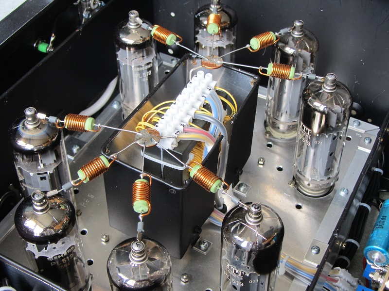 | ||
| 2x 4x PL519 Push-Pull |
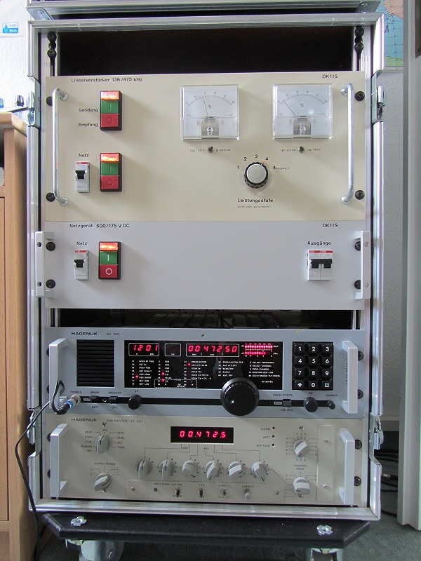 |
| TX, power supply, RX, exciter |
DK1IS has provided an inspiring example of what can be done using vacuum tubes ... they certainly should not be discounted as a viable method of generating your hard-earned LF / MF ERP.
The Artwork Of DK1IS
Recent discussion on the RSGB LF Group reflector about high-powered LF / MF amplifiers brought an interesting response from Tom, DK1IS, and his unique solution.
It's no secret that a Class D / E amplifier using switching MOSFETs is a popular and reasonably inexpensive method of generating some serious RF on the LF and MF bands. Equally well-known is their propensity to gobble-up FETs should the amplifiers encounter much reactance in their output load. Most builders include some form of protection for sudden over-current or unwanted SWR excursions which will shut down the amplifier before any FETs can self-destruct. Those that don't usually end up replacing FETs.
I would venture to guess that over 90% of the transmitters now being employed on LF or MF are using switching MOSFETs in a Class D / E design but there are some amateurs using vacuum tubes to do their heavy-lifting ... and with good results.
DK1IS's beautiful homebrew amplifier is shown below. Tom provided the following description:
Hi Wolf and group,
nice to hear that someone else is thinking about this approach! I´m
content with my homemade tube PA for LF and MF which has provided
reliable service since nearly 4 years now. Only some thoughts about this
concept - I hope not to bore all those hams who are happy with their
semiconductor PAs:
Years ago I had a MOSFET PA for LF, Class B push-pull with 250 W RF. It
worked well at constant conditions, but when I had to retune the antenna
due to larger QSY or made antenna experiments there always was the
danger of blowing up these nervous semiconductors. After 4 or 5 times
changing the MOSFETS I decided to build a new PA - with tubes! Looking a
little bit anachronistic this PA is absolutely good-natured. Designed for
broadband service on LF and MF it makes no problems when changing the
antenna coarse tuning from one band to the other even when the fine
tuning isn't done yet. With my former MOSFET-PA this would have been
impossible.
I wanted to have a linear PA - this usually means class B. You have to
decide between narrow band and broad band (like an audio-amp) design.
For narrow band you can use a single-ended PA but you have to add a
resonance circuit. For broad band you should use a push-pull PA and have
to build a suitable output transformer. I opted for broad band design
because it is usable for LF and MF without changes at the PA. With this
design and sin-driving I reach a total harmonic distortion of about 5 %
at 700 W RF on a pure resistive dummy load. With the usual narrow,
narrow band antennas on LF and MF you don´t need additional filters!
Concerning the tubes: If you take the common TX tubes with plate
voltages of several kV all output circuits have rather high impedances,
that means large coils for the resonance circuits resp. large
transformer windings and very high voltages - potentially a construction
problem. This led me to the choice of 2x 4x PL519 in push-pull, a rugged
colour TV line output tube with low plate voltage and high plate
current. In this way I came down to a plate-to-plate resistance of about
1 kOhm at 600 V DC plate voltage, where you easily can build a ferrite
broad band output transformer down to 50 Ohms. A disadvantage of this
concept is that you have to give individual bias to each tube, that
means for the first start-up you have to align 8 potentiometers
carefully to nearly equal cathode currents for all the tubes. But
according to my experience this alignment remains stable over a long
time. I have inserted 1-Ohm-resistors in each cathode line and have
brought the voltage drops to 8 cinch connectors, where I can monitor the
DC component (with external filtering) as well as the real time current.
With 4 tubes in parallel per branch of course you have to take care for
self oscillations. The extensive use of bypass capacitors, ferrite beads
and parasitic chokes in the plate lines is mandatory as well as good
grounding concepts are. The tubes don´t pull control grid current (this
would even be true in class C!) but you need 3 or 4 W RF input power due
to all the ohmic loads at the tube´s control grids caused by the
individual bias paths. On the other hand this certainly helps to avoid
oscillations. You can see some pictures of this PA at https://www.qrz.com/db/DK1IS
By the way: why not to try these tubes at class D? With DC plate
voltages of perhaps 1200 V you should get a nice QRO-PA ...
Wolf, you are right: building such a PA from scratch is a time consuming
enterprise. I didn´t count the working hours but according to my lab log
the whole project took about 9 months - an adequate time for a new baby!
It was a great experience anyway.
Good luck and 73,
Tom, DK1IS
| ||
| 2x 4x PL519 Push-Pull |
|
| TX, power supply, RX, exciter |
DK1IS has provided an inspiring example of what can be done using vacuum tubes ... they certainly should not be discounted as a viable method of generating your hard-earned LF / MF ERP.


