Author Archive
 The Artwork Of DK1IS
 April 5th, 2017 |
 Author:
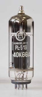
Recent discussion on the RSGB LF Group reflector about high-powered LF / MF amplifiers brought an interesting response from Tom, DK1IS, and his unique solution.
It's no secret that a Class D / E amplifier using switching MOSFETs is a popular and reasonably inexpensive method of generating some serious RF on the LF and MF bands. Equally well-known is their propensity to gobble-up FETs should the amplifiers encounter much reactance in their output load. Most builders include some form of protection for sudden over-current or unwanted SWR excursions which will shut down the amplifier before any FETs can self-destruct. Those that don't usually end up replacing FETs.
I would venture to guess that over 90% of the transmitters now being employed on LF or MF are using switching MOSFETs in a Class D / E design but there are some amateurs using vacuum tubes to do their heavy-lifting ... and with good results.
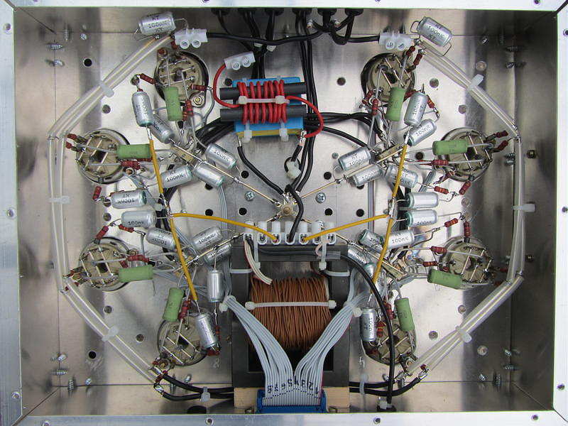
DK1IS's beautiful homebrew amplifier is shown below. Tom provided the following description:
Hi Wolf and group,
nice to hear that someone else is thinking about this approach! I´m
content with my homemade tube PA for LF and MF which has provided
reliable service since nearly 4 years now. Only some thoughts about this
concept - I hope not to bore all those hams who are happy with their
semiconductor PAs:
Years ago I had a MOSFET PA for LF, Class B push-pull with 250 W RF. It
worked well at constant conditions, but when I had to retune the antenna
due to larger QSY or made antenna experiments there always was the
danger of blowing up these nervous semiconductors. After 4 or 5 times
changing the MOSFETS I decided to build a new PA - with tubes! Looking a
little bit anachronistic this PA is absolutely good-natured. Designed for
broadband service on LF and MF it makes no problems when changing the
antenna coarse tuning from one band to the other even when the fine
tuning isn't done yet. With my former MOSFET-PA this would have been
impossible.
I wanted to have a linear PA - this usually means class B. You have to
decide between narrow band and broad band (like an audio-amp) design.
For narrow band you can use a single-ended PA but you have to add a
resonance circuit. For broad band you should use a push-pull PA and have
to build a suitable output transformer. I opted for broad band design
because it is usable for LF and MF without changes at the PA. With this
design and sin-driving I reach a total harmonic distortion of about 5 %
at 700 W RF on a pure resistive dummy load. With the usual narrow,
narrow band antennas on LF and MF you don´t need additional filters!
Concerning the tubes: If you take the common TX tubes with plate
voltages of several kV all output circuits have rather high impedances,
that means large coils for the resonance circuits resp. large
transformer windings and very high voltages - potentially a construction
problem. This led me to the choice of 2x 4x PL519 in push-pull, a rugged
colour TV line output tube with low plate voltage and high plate
current. In this way I came down to a plate-to-plate resistance of about
1 kOhm at 600 V DC plate voltage, where you easily can build a ferrite
broad band output transformer down to 50 Ohms. A disadvantage of this
concept is that you have to give individual bias to each tube, that
means for the first start-up you have to align 8 potentiometers
carefully to nearly equal cathode currents for all the tubes. But
according to my experience this alignment remains stable over a long
time. I have inserted 1-Ohm-resistors in each cathode line and have
brought the voltage drops to 8 cinch connectors, where I can monitor the
DC component (with external filtering) as well as the real time current.
With 4 tubes in parallel per branch of course you have to take care for
self oscillations. The extensive use of bypass capacitors, ferrite beads
and parasitic chokes in the plate lines is mandatory as well as good
grounding concepts are. The tubes don´t pull control grid current (this
would even be true in class C!) but you need 3 or 4 W RF input power due
to all the ohmic loads at the tube´s control grids caused by the
individual bias paths. On the other hand this certainly helps to avoid
oscillations. You can see some pictures of this PA at https://www.qrz.com/db/DK1IS
By the way: why not to try these tubes at class D? With DC plate
voltages of perhaps 1200 V you should get a nice QRO-PA ...
Wolf, you are right: building such a PA from scratch is a time consuming
enterprise. I didn´t count the working hours but according to my lab log
the whole project took about 9 months - an adequate time for a new baby!
It was a great experience anyway.
Good luck and 73,
Tom, DK1IS
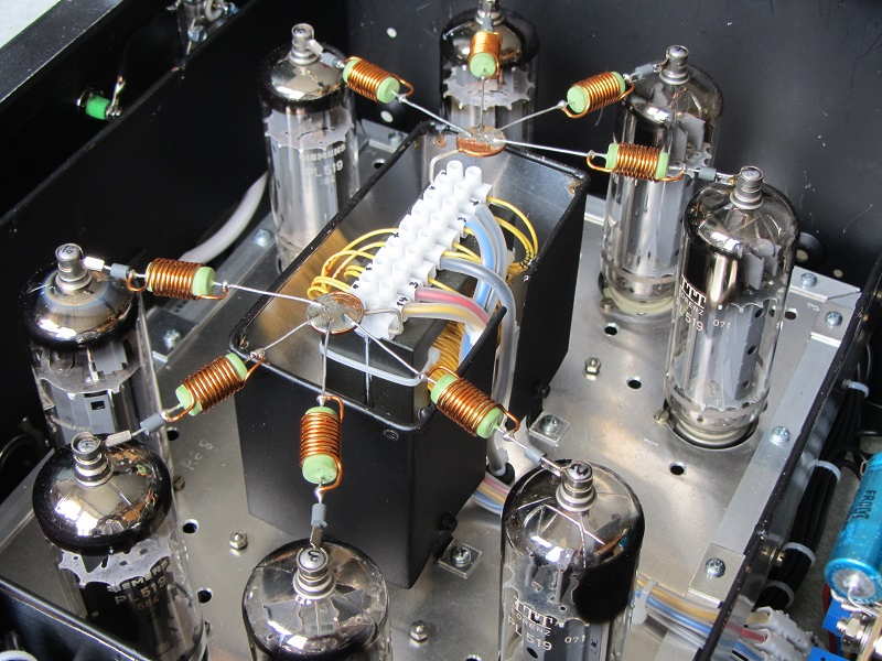 | ||
| 2x 4x PL519 Push-Pull |
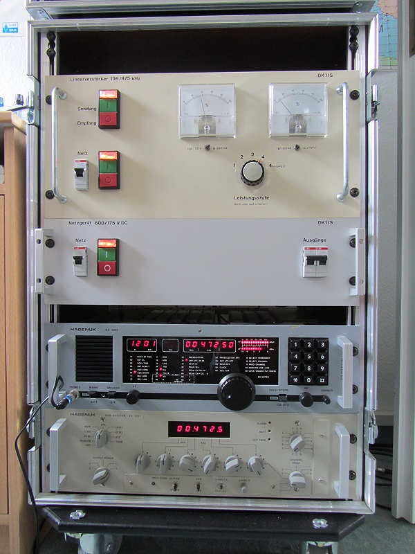 |
| TX, power supply, RX, exciter |
DK1IS has provided an inspiring example of what can be done using vacuum tubes ... they certainly should not be discounted as a viable method of generating your hard-earned LF / MF ERP.
The Artwork Of DK1IS
Recent discussion on the RSGB LF Group reflector about high-powered LF / MF amplifiers brought an interesting response from Tom, DK1IS, and his unique solution.
It's no secret that a Class D / E amplifier using switching MOSFETs is a popular and reasonably inexpensive method of generating some serious RF on the LF and MF bands. Equally well-known is their propensity to gobble-up FETs should the amplifiers encounter much reactance in their output load. Most builders include some form of protection for sudden over-current or unwanted SWR excursions which will shut down the amplifier before any FETs can self-destruct. Those that don't usually end up replacing FETs.
I would venture to guess that over 90% of the transmitters now being employed on LF or MF are using switching MOSFETs in a Class D / E design but there are some amateurs using vacuum tubes to do their heavy-lifting ... and with good results.
DK1IS's beautiful homebrew amplifier is shown below. Tom provided the following description:
Hi Wolf and group,
nice to hear that someone else is thinking about this approach! I´m
content with my homemade tube PA for LF and MF which has provided
reliable service since nearly 4 years now. Only some thoughts about this
concept - I hope not to bore all those hams who are happy with their
semiconductor PAs:
Years ago I had a MOSFET PA for LF, Class B push-pull with 250 W RF. It
worked well at constant conditions, but when I had to retune the antenna
due to larger QSY or made antenna experiments there always was the
danger of blowing up these nervous semiconductors. After 4 or 5 times
changing the MOSFETS I decided to build a new PA - with tubes! Looking a
little bit anachronistic this PA is absolutely good-natured. Designed for
broadband service on LF and MF it makes no problems when changing the
antenna coarse tuning from one band to the other even when the fine
tuning isn't done yet. With my former MOSFET-PA this would have been
impossible.
I wanted to have a linear PA - this usually means class B. You have to
decide between narrow band and broad band (like an audio-amp) design.
For narrow band you can use a single-ended PA but you have to add a
resonance circuit. For broad band you should use a push-pull PA and have
to build a suitable output transformer. I opted for broad band design
because it is usable for LF and MF without changes at the PA. With this
design and sin-driving I reach a total harmonic distortion of about 5 %
at 700 W RF on a pure resistive dummy load. With the usual narrow,
narrow band antennas on LF and MF you don´t need additional filters!
Concerning the tubes: If you take the common TX tubes with plate
voltages of several kV all output circuits have rather high impedances,
that means large coils for the resonance circuits resp. large
transformer windings and very high voltages - potentially a construction
problem. This led me to the choice of 2x 4x PL519 in push-pull, a rugged
colour TV line output tube with low plate voltage and high plate
current. In this way I came down to a plate-to-plate resistance of about
1 kOhm at 600 V DC plate voltage, where you easily can build a ferrite
broad band output transformer down to 50 Ohms. A disadvantage of this
concept is that you have to give individual bias to each tube, that
means for the first start-up you have to align 8 potentiometers
carefully to nearly equal cathode currents for all the tubes. But
according to my experience this alignment remains stable over a long
time. I have inserted 1-Ohm-resistors in each cathode line and have
brought the voltage drops to 8 cinch connectors, where I can monitor the
DC component (with external filtering) as well as the real time current.
With 4 tubes in parallel per branch of course you have to take care for
self oscillations. The extensive use of bypass capacitors, ferrite beads
and parasitic chokes in the plate lines is mandatory as well as good
grounding concepts are. The tubes don´t pull control grid current (this
would even be true in class C!) but you need 3 or 4 W RF input power due
to all the ohmic loads at the tube´s control grids caused by the
individual bias paths. On the other hand this certainly helps to avoid
oscillations. You can see some pictures of this PA at https://www.qrz.com/db/DK1IS
By the way: why not to try these tubes at class D? With DC plate
voltages of perhaps 1200 V you should get a nice QRO-PA ...
Wolf, you are right: building such a PA from scratch is a time consuming
enterprise. I didn´t count the working hours but according to my lab log
the whole project took about 9 months - an adequate time for a new baby!
It was a great experience anyway.
Good luck and 73,
Tom, DK1IS
| ||
| 2x 4x PL519 Push-Pull |
|
| TX, power supply, RX, exciter |
DK1IS has provided an inspiring example of what can be done using vacuum tubes ... they certainly should not be discounted as a viable method of generating your hard-earned LF / MF ERP.
LF and MF Now Very Close For U.S. Amateurs!
For U.S. amateurs anxiously awaiting implementation of the new 630m and 2200m bands, the wait seems to be almost over!
Good news came down late yesterday in the form of the FCC's "Report and Order" (ET Docket No. 15-99) which lays out the proposed rules and regulations that, barring any further changes, will likely become standard operating procedures once these two bands become finalized.
Highlights of the FCC's document are as follows:
1. Recognition that both Utilities (UTC) and amateurs can co-exist within these parts of the spectrum:
... co existence between PLC systems and amateur radio operations in these bands is possible, and the service rules we adopt in this Order will foster this co existence.
2. Amateurs operating within these bands must be no closer than 1 km from transmission lines that are actively carrying PLC (control) signals:
As proposed, we will permit amateur stations to operate in the 135.7-137.8 kHz and 472-479 kHz bands when separated by a specified distance from electric power transmission lines with PLC systems that use the same bands. To support the operations of both the amateur service and PLC systems in these bands, we adopt a minimum horizontal separation distance of one kilometer between the transmission line and the amateur station when operating in these bands.
We find that a one kilometer separation distance reasonably ensures that PLC systems and amateur radio stations are unlikely to experience interference. In addition, establishing a zone where amateur use is not authorized will simplify and streamline the process for determining whether an amateur station can transmit in these bands when in proximity to transmission lines upon which PLC systems operate.
3. Amateurs must "make notification" to local UTC authorities before commencing operation on either of these two bands:
We will require amateur operators to notify UTC of the location of their proposed station prior to commencing operations, to confirm that the station is not located within the one kilometer separation distance.
The notification requirement will entail notifying UTC of the operator’s call sign and coordinates of the proposed station’s location for confirmation that the location is outside the one kilometer separation distance, or the relevant PLC system is not transmitting on the requested bands. UTC, which maintains a database of PLC systems must respond to the notification within 30 days if it objects. If UTC raises no objection, amateur radio operators may commence operations on the band identified in their notification. The Wireless Telecommunications Bureau will issue a public notice providing the details for filing notifications with UTC.
A simple notification to UTC with a 30-day waiting period does not appear to be burdensome. Amateur operations can commence as soon as that period expires. ARRL claims that UTC should provide access to the PLC database to them or directly to amateurs to assist them in determining whether their notified operations are within the one-kilometer separation distance from transmission lines with PLC systems operating on these bands. ARRL fails to make a persuasive case why it would be a better organization to make those determinations rather than UTC. Further, since UTC has control of the PLC database which can be updated, we find no reason to mandate its release to another party especially considering the sensitive nature of information it contains.
4. Power limits will be expressed in EIRP as well as maximum PEP:
Amateur stations may operate in the 135.7-137.8 kHz band with a maximum radiated power of one watt EIRP ... that amateur stations operating in the 135.7-137.8 kHz band should be subject only to the general Part 97 limit of 1.5 kW peak envelope power (PEP).
We also adopt the power limits proposed in the WRC-12 NPRM for amateur stations operating in the 472-479 kHz band. For such stations, the maximum radiated power will be five watts EIRP, except for stations located in the portion of Alaska that is within 800 kilometers of the Russian Federation, where the EIRP will be limited to one watt. We also limit the transmitter power for amateur radio operations in the 472 479 kHz band to 500 watts PEP; provided, however, that the resulting radiated power does not exceed five watts EIRP. In other words, it may be necessary to reduce transmitter power below 500 watts PEP to avoid exceeding the five watts EIRP limit.
5. Antenna height will be limited:
... we will require that the antennas used to transmit in these bands not exceed 60 meters in height above ground level (AGL), as ARRL proposed.
6. Regarding transmission modes, no bandwidths have been specified in order to encourage experimentation:
Consistent with our proposal in the WRC-12 NPRM, and with the existing rules in Section 97.305 for the frequency bands below 30 MHz, we authorize amateur stations to transmit the following emission types throughout the new amateur bands: CW (international Morse code telegraphy), RTTY (narrow-band direct-printing telegraphy), data, phone, and image emissions. These emission types provide amateur operators with maximum flexibility, and we find that additional restrictions would needlessly hinder experimentation.
7. Experimental stations appear to 'still be in business' but are encouraged to transition to the 'amateur' service:
Finally, we decline to permit previously licensed experimental stations – some of which have been authorized with significantly more radiated power than the adopted EIRP limits for these new amateur service bands – to communicate with amateur stations operating in these bands. Amateur operations in these bands currently authorized under experimental licenses should transition their operations in accordance with the adopted rules and not circumvent such rules by use of experimental licenses.
My understanding of the R&O document is that participating parties may still file a 'Petition For Reconsideration' notification within 30 days of the R&O's publication in the Federal Register. Once these (if any) are dealt with, there are no other roadblocks preventing immediate implementation.
The document contains additional details not discussed here and makes fascinating reading for amateurs that might be looking forward to the new allocations.
This is the news that many U.S. amateurs have been waiting many years to hear! It is also good news for Canadian's operating on these bands to know that they may soon see a large increase in activity south of the border. Let's hope things continue to transpire favorably and that we will finally see the new bands become a reality.
Get those soldering irons out guys and gals!
LF and MF Now Very Close For U.S. Amateurs!
For U.S. amateurs anxiously awaiting implementation of the new 630m and 2200m bands, the wait seems to be almost over!
Good news came down late yesterday in the form of the FCC's "Report and Order" (ET Docket No. 15-99) which lays out the proposed rules and regulations that, barring any further changes, will likely become standard operating procedures once these two bands become finalized.
Highlights of the FCC's document are as follows:
1. Recognition that both Utilities (UTC) and amateurs can co-exist within these parts of the spectrum:
... co existence between PLC systems and amateur radio operations in these bands is possible, and the service rules we adopt in this Order will foster this co existence.
2. Amateurs operating within these bands must be no closer than 1 km from transmission lines that are actively carrying PLC (control) signals:
As proposed, we will permit amateur stations to operate in the 135.7-137.8 kHz and 472-479 kHz bands when separated by a specified distance from electric power transmission lines with PLC systems that use the same bands. To support the operations of both the amateur service and PLC systems in these bands, we adopt a minimum horizontal separation distance of one kilometer between the transmission line and the amateur station when operating in these bands.
We find that a one kilometer separation distance reasonably ensures that PLC systems and amateur radio stations are unlikely to experience interference. In addition, establishing a zone where amateur use is not authorized will simplify and streamline the process for determining whether an amateur station can transmit in these bands when in proximity to transmission lines upon which PLC systems operate.
3. Amateurs must "make notification" to local UTC authorities before commencing operation on either of these two bands:
We will require amateur operators to notify UTC of the location of their proposed station prior to commencing operations, to confirm that the station is not located within the one kilometer separation distance.
The notification requirement will entail notifying UTC of the operator’s call sign and coordinates of the proposed station’s location for confirmation that the location is outside the one kilometer separation distance, or the relevant PLC system is not transmitting on the requested bands. UTC, which maintains a database of PLC systems must respond to the notification within 30 days if it objects. If UTC raises no objection, amateur radio operators may commence operations on the band identified in their notification. The Wireless Telecommunications Bureau will issue a public notice providing the details for filing notifications with UTC.
A simple notification to UTC with a 30-day waiting period does not appear to be burdensome. Amateur operations can commence as soon as that period expires. ARRL claims that UTC should provide access to the PLC database to them or directly to amateurs to assist them in determining whether their notified operations are within the one-kilometer separation distance from transmission lines with PLC systems operating on these bands. ARRL fails to make a persuasive case why it would be a better organization to make those determinations rather than UTC. Further, since UTC has control of the PLC database which can be updated, we find no reason to mandate its release to another party especially considering the sensitive nature of information it contains.
4. Power limits will be expressed in EIRP as well as maximum PEP:
Amateur stations may operate in the 135.7-137.8 kHz band with a maximum radiated power of one watt EIRP ... that amateur stations operating in the 135.7-137.8 kHz band should be subject only to the general Part 97 limit of 1.5 kW peak envelope power (PEP).
We also adopt the power limits proposed in the WRC-12 NPRM for amateur stations operating in the 472-479 kHz band. For such stations, the maximum radiated power will be five watts EIRP, except for stations located in the portion of Alaska that is within 800 kilometers of the Russian Federation, where the EIRP will be limited to one watt. We also limit the transmitter power for amateur radio operations in the 472 479 kHz band to 500 watts PEP; provided, however, that the resulting radiated power does not exceed five watts EIRP. In other words, it may be necessary to reduce transmitter power below 500 watts PEP to avoid exceeding the five watts EIRP limit.
5. Antenna height will be limited:
... we will require that the antennas used to transmit in these bands not exceed 60 meters in height above ground level (AGL), as ARRL proposed.
6. Regarding transmission modes, no bandwidths have been specified in order to encourage experimentation:
Consistent with our proposal in the WRC-12 NPRM, and with the existing rules in Section 97.305 for the frequency bands below 30 MHz, we authorize amateur stations to transmit the following emission types throughout the new amateur bands: CW (international Morse code telegraphy), RTTY (narrow-band direct-printing telegraphy), data, phone, and image emissions. These emission types provide amateur operators with maximum flexibility, and we find that additional restrictions would needlessly hinder experimentation.
7. Experimental stations appear to 'still be in business' but are encouraged to transition to the 'amateur' service:
Finally, we decline to permit previously licensed experimental stations – some of which have been authorized with significantly more radiated power than the adopted EIRP limits for these new amateur service bands – to communicate with amateur stations operating in these bands. Amateur operations in these bands currently authorized under experimental licenses should transition their operations in accordance with the adopted rules and not circumvent such rules by use of experimental licenses.
My understanding of the R&O document is that participating parties may still file a 'Petition For Reconsideration' notification within 30 days of the R&O's publication in the Federal Register. Once these (if any) are dealt with, there are no other roadblocks preventing immediate implementation.
The document contains additional details not discussed here and makes fascinating reading for amateurs that might be looking forward to the new allocations.
This is the news that many U.S. amateurs have been waiting many years to hear! It is also good news for Canadian's operating on these bands to know that they may soon see a large increase in activity south of the border. Let's hope things continue to transpire favorably and that we will finally see the new bands become a reality.
Get those soldering irons out guys and gals!
Another Blast Coming
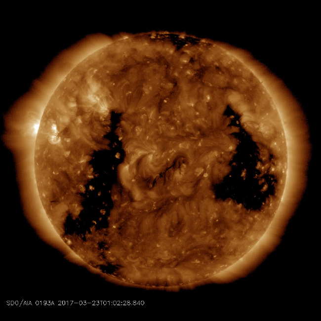 |
| courtesy: https://sdo.gsfc.nasa.gov/ |
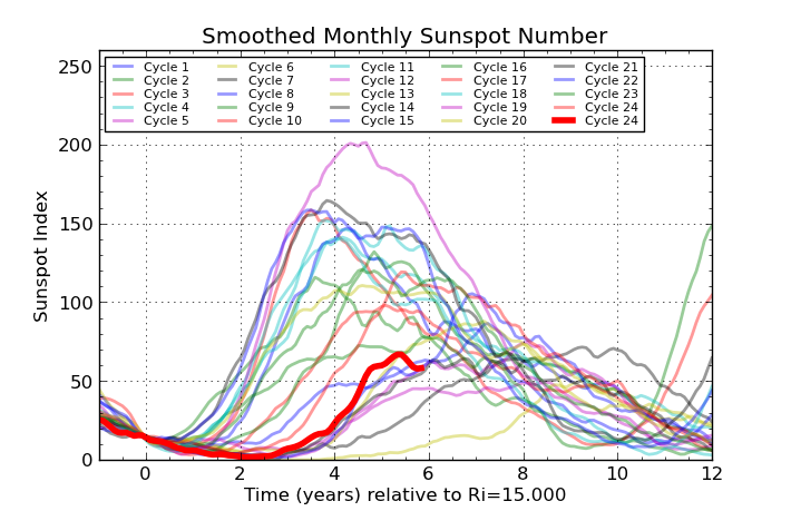
Speaking of 'everlasting', wimpy Solar Cycle 24 has been showing more energy in its death throws than it ever seemed to show during its peak.
It continues to blast earth with a never-ending series of coronal hole streams leading to periods of high signal absorption (particularly on the lower frequencies) and widespread auroras.
The present rip in the Sun's surface is the same one that caused major disruptions during the last solar rotation. Geomagnetic storming and propagation disruptions are forecast to begin around the 28th, with a proviso ... these ones could be even worse than last time as the wind's polarity at present is favorable to greater coupling with the Earth's magnetosphere, sending the Earth's Bz southward (negative) into auroral producing, prop-killing conditions.
Sometimes, though not normally, these events can produce periods of enhanced low frequency propagation, especially during the hours just before the event's commencement ... the best thing to do is just continue to operate normally and not assume the worst. I've been guilty of this in the past and being caught off guard, have missed some better than usual LF propagation.
I'll keep my fingers crossed over the next few days and think positive ... Bz-wise!
Another Blast Coming
|
| courtesy: https://sdo.gsfc.nasa.gov/ |
Speaking of 'everlasting', wimpy Solar Cycle 24 has been showing more energy in its death throws than it ever seemed to show during its peak.
It continues to blast earth with a never-ending series of coronal hole streams leading to periods of high signal absorption (particularly on the lower frequencies) and widespread auroras.
The present rip in the Sun's surface is the same one that caused major disruptions during the last solar rotation. Geomagnetic storming and propagation disruptions are forecast to begin around the 28th, with a proviso ... these ones could be even worse than last time as the wind's polarity at present is favorable to greater coupling with the Earth's magnetosphere, sending the Earth's Bz southward (negative) into auroral producing, prop-killing conditions.
Sometimes, though not normally, these events can produce periods of enhanced low frequency propagation, especially during the hours just before the event's commencement ... the best thing to do is just continue to operate normally and not assume the worst. I've been guilty of this in the past and being caught off guard, have missed some better than usual LF propagation.
I'll keep my fingers crossed over the next few days and think positive ... Bz-wise!
The Everlasting Ameco AC-1
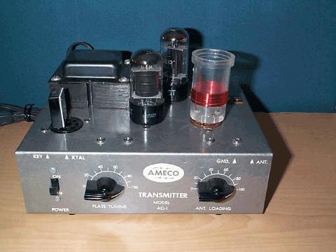 |
| courtesy: WB1GFH's AC-1 site |
I continue to be amazed at the high prices being paid on E-Bay for original Ameco AC-1 transmitters but perhaps I shouldn't ... they've been doing this for several years now.
Few radios that I can think of have elevated themselves to the cult status enjoyed by the AC-1, but the 3-tube Knight Ocean Hopper regen also comes to mind. Both radios typically reach $100- $200 on auction, with some going for much more. There were plenty of AC-1's sold and built over the years so it's not as if they're rare.
They seem to pop up frequently on E-Bay and the auctions are usually very spirited. I see a nice looking one at present, with 23 bids so far and now at $150! I guess the timing is just about right, with a large supply of now-retired ex-50's Novices who once owned an AC-1, looking to turn back the clock and recreate their early radio experience.
As transmitters go, they don't come much simpler, but the well-designed and smartly marketed radio made it extremely popular among the vast numbers of newly-licenced teenaged Novices who likely didn't have much spare change ... the first ones hit the market in the late 50's, right in time for the strongest solar cycle on record, selling for $14.95 in kit form. AC-1's continued to be sold into the early 70's with the price rising to around $25 ... a nice long run for most ham gear. I may be wrong but I don't think they were ever available in anything other than kit form.
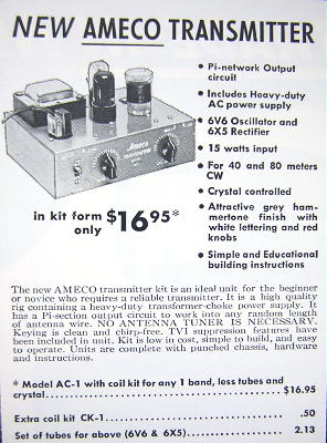
Here is what the kit looked like upon arrival ... this one still NIB in 2012!
 |
| courtesy: http://www.wa0itp.com/ac-1.html |
There is also a large builder's interest in making AC-1 'clones' along with a dedicated Yahoo Group for additional support. Several years go I decided to scratch-build my own clone and found that I had everything needed except for the gray hammertone spray paint. Although most AC-1's used black chicken head knobs, some early models used maroon knobs so I decided to go with a red slide switch and red chicken head knobs on my reproduction. The important decal was available at the time from the Yahoo group but I see them now being sold by Radio Daze, for those that may want to try their hand at building a clone themselves.

The AC-1 uses the inexpensive 6V6 elevated from AF to RF duty, in a crystal-friendly Colpitts crystal oscillator. The only departure from the norm is the output circuit. Most inexpensive one-tubers end up with a link-coupled output but the AC-1 uses the more versatile pi-network ... something that no doubt added to its production costs but produced a transmitter able to load a wider range of antenna impedances while providing superior harmonic attenuation, both important in a beginner's rig.
My clone puts out 8 watts on 80m and 7 watts on 40m. Although never intended, doubling to 20m sees a large drop in efficiency, with output power dropping to 2 watts. Swapping to a 6L6 yields an extra couple of watts. Not enough to be noticed at the other end except when doubling or tripling.
I haven't had my clone on the air for a few years and think it's time to spark it up once again for some summertime fun on 40m CW. It would be great to work another clone or even a real AC-1 if you have one, but any contacts will be exciting if you would like to try.
I'll be hanging around 7118 kHz or down near 7040 and ... I won't be loud!