Author Archive
 Morsemail and LCWO.net
The time has come when I can’t put off learning Morse code any longer, With an interest in vintage amateur radio and the impending restoration of a Heathkit AT-1 I’m going to need to use CW sooner or later.
So I have been checking out resources for learning Morse code and stumbled across two that really intrigue me.
The first is LCWO.net, a web browser based Morse code learning tool that is usable on any internet connected computer. It is available free of charge and there is no software to install. LCWO.net keeps track of where you are in your lessons and where you need to concentrate your effort. The Koch method is the primary tool available but they also offer code group practice, callsign and plain text training modes along with a service to convert text to Morse MP3s for download and use offline.
Once you are on the way to CW proficiency and want to communicate with others you can always fire up a rig and get on the air … What if you don’t have a rig or need a confidence boost before ‘going live’?
Well, you could always send Morsemail using the Morsemail client from http://brasspounder.com:8873/.
Morsemail is, “A simple text format that encodes mark and space times to make it possible to send Morse coded messages via email” but a recently added feature allows for QSOs using a internet repeater hosted on brasspounder.com. You can use a mouse or actual key wired to the mouse or joystick buttons to send CW which can be emailed or sent through the repeater live.
Now I just have to carve out the time to sit down and use these resources!
DIY Magnetic Loop Antenna – Part 2
Part 1 of the DIY Magnetic Loop Antenna covered mostly theory and materials so now its time to move on to designing the magnetic loop antenna (MLA).
If you have priced a commercially made MLA you’ll see prices start at $400 and keep going up, and up. If they cost so much you would think they must be difficult to build or use expensive parts, right? Well, it is certainly possible to spend more and get a higher quality MLA but a low cost MLA will still work very well.
For the purposes of this article we’ll assume that you want to build a loop to cover the 20-10M bands. I’ll run through the calculations required to build the MLA.
The required information for the MLA calculator is:
- Length of the loop
- The conductor diameter
- Frequency/s of operation
- Input power to the antenna
- We don’t really know the best length of the loop at the moment so I’ll pick 9 feet circumference as a starting point (It’ll still fit in the trunk of my car)
- Since we seem to be having better luck with sunspots now I’d like to try 10M so we’ll start with 29 Mhz as the highest frequency we’ll use.
- I have some copper pipe left over from an ice-maker install, it is 1/4 (0.25) inch in diameter.
- Input power to the loop will be 100W.
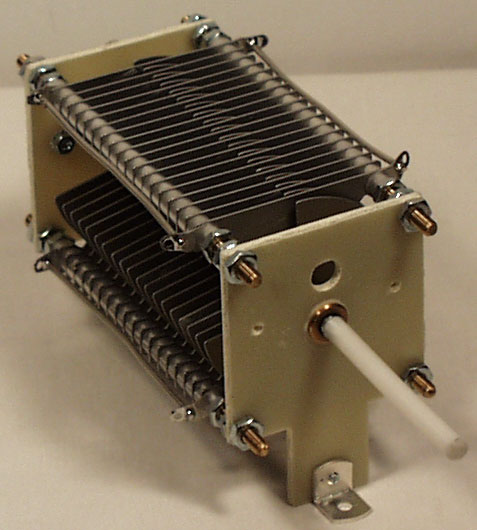
 A peak voltage of 5181V will require a minimum spacing of 1.7 mm (peak voltage / breakdown voltage per mm) between the closest conductors in the capacitor. That would rule out an old air spaced variable capacitor from a vacuum tube radio but you could still use a wide spaced variable capacitor from an antenna matching unit or transmitter. A vacuum variable capacitor would be great (watch the minimum capacitance) or a home-made capacitor would also be fine provided you checked the breakdown voltage of the insulating material.
 DIY Magnetic Loop Antenna – Part 1
Do you live in a neighborhood with a restrictive antenna policy and despair of having a useful HF antenna?
Can you solder or know someone who can?
A magnetic loop antenna may be the answer and they are not as difficult to build as you might think. Like getting on the air for the first time or taking your license exam there is a certain amount of uncertainty when you first approach magnetic loop antennas, there are a few new ideas to grasp. However, thanks to other hams like Steve AA5TB there are tried and tested designs, calculators & building methods that are known to work and that you can follow.
 At the heart of every radio and MLA (Magnetic Loop Antenna) is the resonant circuit. The combination of an inductor (a wire has inductance, but a coil of wire has more) and a capacitor (two conductors separated by an insulator) in a circuit will resonate or ‘ring’ at a certain frequency. Sound vibrations at a certain frequency can cause a piano string to vibrate in sympathy and a vibration of the correct radio frequency will cause a resonant circuit to electrically vibrate in sympathy.
Since there is no such thing as a free lunch, the sacrifice you make with a MLA is that it needs to be re-tuned whenever you change frequency on your transceiver. The frequency range over which it is resonant is very small, typically only a few hundred kilohertz at the most.
The materials you can get your hands on is going to decide the capabilities of your MLA. Ideally you’ll have a loop made from a conductor with very low resistance (usually copper) and a capacitor that can handle high voltages. A variable capacitor is required if you want to use your antenna on multiple frequencies but you can use or make a fixed capacitor if you operate on one frequency, for Eg PSK31.
A MLA calculator like the Excel spreadsheet from Steve AA5TB or this web page from 66pacific.com will help you to decide what size components you’ll need to make your antenna.
The four pieces of information required are:
- What frequency or frequencies do you wish to transmit on?
- How large do you want the loop to be (It should have a circumference less than 10% of the design frequency wavelength, both calculators help you figure this out)
- The diameter of your conductor (Three quarter inch (0.75 inch) copper pipe is a good start)
- How much power you want to use (The voltage across the capacitor is proportional to the input power to the MLA)
 A MLA of a certain circumference will be more or less efficient based on the frequency you transmit at. It is worth changing the loop size in the calculator to get the best efficiency possible in your favorite band.
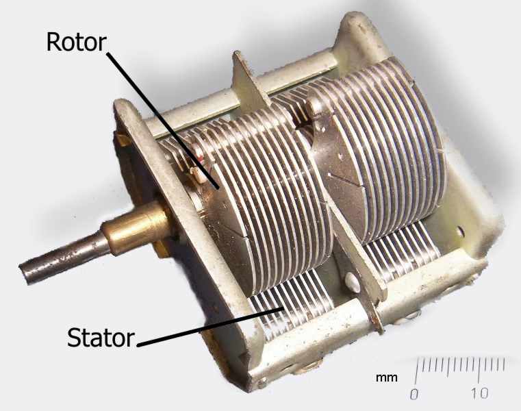
Now I understand – Phase Locked Loops
Every now and then I come across great books or videos that explain a concept in such a way that it becomes immediately obvious what is going on. I’m a great believer in learning by demonstration or even better, learning by doing.
I came across another explanatory video recently that I thought was too good to keep to myself. It covers a topic that was a complete mystery to me: Phase Locked Loops. We utilize them in almost every modern transmitter and receiver yet most people I have talked to view them as a black box that, fortunately, does its job well and usually without interruption.
The video below does a good job on opening the black box and showing just what makes phase locked loops … well, lock.
Heathkit’s first amateur transmitter – Heathkit AT-1
The Heathkit AT-1 represents the commercial embodiment of the simple Master Oscillator Power Amplifier (MOPA) transmitter using a crystal controlled 6AG7 oscillator plus a 6L6 final output tube.
Although it was possible to design and build a simpler transmitter, the goals of output power and stability could become mutually exclusive when trying to operate with only one tube. For a novice class license holder of 1951 the Heathkit AT-1 represented a solid performing rig that would be relatively easy to construct and operate.
The Novice remained the primary entry license until the Morse code requirement was eliminated for Technician licenses in 1990. On HF it permitted code transmissions only, with a maximum power of 75 watts, (input to the transmitter’s final amplifier stage) on limited segments of the 80, 40 and 15 meter bands.
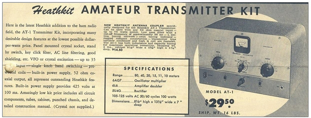 |
| For $29.50 and the loan of a few tools you could get some use out of that new novice license |
The earlier MOPA circuit from the ARRL handbook of 1941 below shows a layout remarkably similar to the circuit of the AT-1 although it is designed for plug in coils rather than the band-switching arrangement of the later Heathkit transmitter.
| MOPA transmitter using a 6L6 and an 807 as the power amplifier (ARRL Handbook 1941) |
For a little added complexity MOPA transmitters generally offered better stability of frequency and keying waveform than single tube crystal controlled or self exited rigs. The straight forward design of the AT-1 should have looked familiar to novice class hams after studying the ARRL handbook or other radio publications.
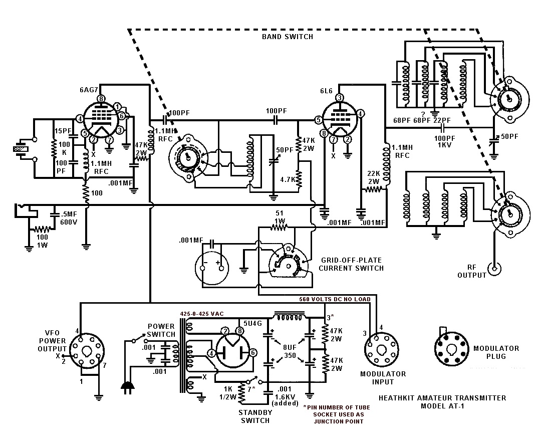 |
| Heathkit AT-1 Circuit diagram showing band-switching arrangement and link coupled output |
Once the novice had upgraded his license the AT-1 could be expanded by the addition of the Heathkit VF-1 variable frequency oscillator to allow transmission on any frequency within the allowed band.
 |
| The Heathkit VF-1 Variable Frequency Oscillator |
The VF-1 covered 160-80-40-20-15-11-10 meters and used an OA2 voltage regulator tube to provide a stable voltage for the oscillator. Ceramic coil forms, solid construction and high quality components were used to help increase stability.
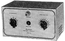 |
| The Heathkit AC-1 Antenna Coupler. Designed to attach to a single wire by the insulated post on the front panel. |
 |
| Heathkit AC-1 Antenna Coupler circuit diagram |
Although Heathkit did not produce a AM modulator for the AC-1 there is provision for modulator connection on the rear panel. The earlier ARRL manuals have several suitable circuits for modulators that would work with the AC-1. Most functioned by driving a modulation transformer with the output from an audio power amplifier. The secondary of the modulation transformer would be carrying the DC plate supply for the power amplifier tube plus or minus the instantaneous voltage of the audio waveform. By changing the plate voltage to the final amplifier tube the radio frequency output would be controlled by the amplified audio frequency resulting in amplitude modulation.
South Texas Balloon Launch Team launches balloon aimed at China
My daughter and I made the short trip to the No Label Brewing Company in Katy TX to watch the South Texas Balloon Launch Team launch a helium balloon aimed at Nanjing China. Thanks to Tom AE5QB for letting us know about this event!
To track the balloon in real time go to : http://aprs.fi/?call=a%2FKT5TK-11&_s=mb
From the press release of the South Texas Balloon Launch Team:
The South Texas Balloon Launch Team is pleased to announce the upcoming launch of its twenty-eighth, helium-filled, unmanned balloon in twenty one years. The purpose of this flight is to establish a world record for distance by floating a balloon from Katy, Texas to Nanjing, China.
The balloon will be released at approximately 3 P.M. CST on Saturday, February 11, 2012. The site of the launch is at the western end of the No Label Brewery complex at 5373 First St., Katy Texas, near the old rice grain silos.
The public is invited to this free event, with a special invitation to science students and teachers. Free helium-filled balloons will be available to the first 100 students. Sorry, no pets allowed in the balloon area.
The balloon payload package weighs only about five ounces (150 grams) and contains a high altitude GPS tracking system and a VHF amateur radio transmitter. To conserve weight and battery life, no camera equipment will be on board. The maximum altitude is expected to be above 100,000 feet, with horizontal speeds between 100 and 150 MPH. The balloon size will increase from about five feet to about 39 feet at maximum elevation. Recovery of the payload package is not expected.
Individuals may follow the balloon’s progress on the Internet by logging onto APRS, filling in the “track callsign” field with “kt5tk-11”, and change the “show last” to 24 hours.
The South Texas Balloon Launch Team is composed of about twenty active amateur radio “Ham” operators from a variety of occupations who donate their time and expertise.
We appreciate the continued support by No Label Brewing Company for our amateur radio projects.
Pop’s Shed and the Kingsley Radio AR7
After my grandfather passed away I spent a lot of time recalling the good times I had spent scrounging around his CB shack and hanging out with Pop “down the shed”. If you’ve spent time around old motorbikes, retired lawn mower engines, vacuum tube electronics and inches of dust you know what the shed smelt like and probably have a pretty good idea what it looked like as well. I used to be able to send Mum into fits by embedding a combination of oil, grease, dust and grinding compound into the knees and sleeves of my good clothes after spending the day “over south” (South Geelong)
Even now I can still walk into any old auto mechanics and the smell brings back dozens of memories as clear as day … but one memory in particular had been bugging me for a while now. On several occasions I had used a magnificent rack mounted shortwave receiver that had been hooked to a long-wire antenna between the shed and the house. It had several plug in coils housed in bright metal boxes, one for each band as well as a unique tuning dial that had windows around the circumference with numbers that updated as the dial was turned.
 |
| National HRO right? … Nope, its an Australian clone! |
For the longest time I was thinking what you are probably thinking now, I had been using a National HRO receiver right? Well, you’d be wrong … just as I had been for years! When I eventually asked my uncle about the receiver (I waited a long time as I feared it had been thrown out & honestly didn’t want to know if it had) he said, “The AR7?” … “Yes, its here in the garage covered in dust”. He went on to say that I could have the receiver if I could figure out some way to ship it … not a slight problem given the receiver, power supply and speaker are over 120 lbs!
Knowing now that I had been using a completely different receiver I set to work and found out what I could about this National HRO clone …
From : http://www.vk2bv.org/
The AR7 was produced during WW2 by Kingsley Radio of Melbourne for the R.A.A.F. These receivers were used in ground stations for long range communication over fixed circuits as well as for receiving signals from aircraft.
The AR7 was based largely on the National (USA) HRO model, a fact that did not go unnoticed by National. This was the subject of litigation during the war years. Over 3000 of these receivers were produced and for their time, produced excellent performance.
These sets were very popular with radio amateurs after the war and unfortunately subject to many modifications. The Wireless Institute of Australia station, VK2WI at Dural New South Wales was equipped with modifed AR7’s for many years. I seem to remember that very local operators could block the receivers completely, resulting in hurried phone calls!
An unmodified AR7 is a rare beast. The Department of Civil Aviation used these sets for many years in a highly modified form, requiring a new front panel. Refinements included squelch and crystal locked coil boxes.
From : http://www.shlrc.mq.edu.au/~robinson/museum/AR7/
The AR7 is a communications receiver covering LF and HF bands. It was made in Australia during 1940 and bears an extremely close resemblance to the National HRO receiver. The receiver has a tuning range from 138 kcs to 25 mcs, with a gap of 45 kcs either side of the 455 kcs IF amplifier. The internal design is a single conversion superheterodyne receiver with 2 RF stages, 2 IF stages, a BFO and an “S” meter amplifier. The sensitivity is quoted as 1 microvolt. The front panel is stainless steel and it is a very distinctive looking receiver.
It is a good performer, sensitive, has a nice feel, is easy to tune, but hard to find the correct frequency, by reading the frequency from the dial number and coil box graph. It really needs a crystal calibrator. I use it for the weekly W.I.A. (Wireless Institute of Australia) broadcast, so it gets turned on once a week, and is so stable, than I don’t have to retune. It is very clear for AM but a bit fiddly for SSB.
The controls are: RF gain, BFO note, AVC/BFO switch, Adjust “S” meter, Tone, Tuning, Noise limiter, Selectivity, Crystal IN/OUT switch, Crystal Phasing, Audio gain. The Audio gain control has an OFF position which removes the HT so that the coil boxes can be changed.

It has two 6U7G RF stages, a 6K8G mixer, two 6U7G IF stages at 455 kcs, a 6G8G detector/AVC/audio preamplifier, and a 6V6G audio output amplifier. It has a 6C8G twin triode as a BFO and “S” meter amplifier. It also has a crystal filter. The IF alignment should be done very carefully, as any misalignment will reduce the effectiveness of the filter. It is best done with a sweep generator. The 6 volt valve heaters are connected in series, for 12 volt operation.
The external power supply and speaker, are usually mounted in a short 19″ rack, the AR7 at the bottom, the speaker in the middle, and the power supply at the top. The complete unit weighs about 118 pounds. The power supply was switchable between 12v and 240v.
The receiver was used as a ground monitoring receiver for aircraft. It was extremely stable. The model shown has an R.A.A.F. nameplate, and serial number 1786. The manual I have is a D.C.A. (Department of Civil Aviation) version and is a 1947 issue.
It has 5 plug in coil boxes. The coil boxes are: band A 140-405 kcs, band B 490-1430 kcs, band C 1.420-4.3 mcs, band D 4.25-12.5 mcs, band E 12.5-25 mcs. The Army version had an extra coil box covering 50-150 kcs. The large dial is a 20:1 reduction drive and has graduations from 0 to 500. It acts like a flywheel when tuning across the band, and has an effective scale length of 12 feet. The dial shaft goes into a right angle reduction gearbox and has 2 output shafts that drive 2 dual gang capacitors. The graph on the front of each coil box is used to covert the dial reading to frequency.


