Author Archive
 Ham Radio and Mesh Networks
Lately I’ve been fascinated by the capabilities of mesh networks. The ability to quickly create ad-hock computer networks could be an invaluable resource for amateur radio operators in general and particularly for emergency communications (EMCOM)

The particular device and software I have been experimenting with is the Linksys WRT54G router and HSMM-MESH firmware from http://hsmm-mesh.org/.
Installing the HSMM-MESH firmware changes the way the Linksys router functions and allows it to automatically connect to other HSMM routers in a mesh network. No special configuration is required after setting your callsign. All TCP/IP configuration is pre-configured, even down to automatically assigning addresses to connecting clients.

Mesh networks are highly fault tolerant. Every router in the network is aware of every other router and has the ability to move network packets through from one unit to another provided there is a link, or chain of linked routers, between them.
In the diagram to the right each router is represented by a numbered circle. If router number 6 were to fail then network packets that needed to move between router 1 and 7 would travel through routers 2 & 3 or 5 & 10 until 6 was repaired. All this happens automatically and quickly enough so that there is no disruption to the traffic.
Anything you can access on a normal computer network can be made to work on a mesh network. Some of the services that have been demonstrated include email, voice over IP (VOIP), video conferencing, file sharing, web servers & groupware applications.
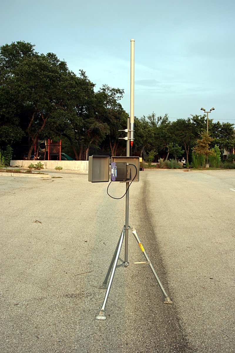 With simple modified antennas the modest output power from the WRT54G (100 to 200mW) can be used to reach distances of many miles or tens of miles with directional antennas. Mounting the router on a mast in a sealed enclosure can reduce losses from long cable runs while running off 12V power makes them compatible with ham radio power sources including solar and wind power.
The example to the left is from NG5V located on hsmm-mesh.org and consists of an omni-directional external antenna and a lawn sprinkler controller box from a popular home improvement store.
Did you know that … Frequencies used by channels one through six of 802.11b and 802.11g fall within the 2.4 GHz amateur radio band. Licensed amateur radio operators may operate 802.11b/g devices under Part 97 of the FCC Rules and Regulations, allowing increased power output but not commercial content or encryption.
I hope to acquire a few more WRT54G routers and put together a mesh network in the Katy TX area as a resource for experimentation and education in an area not normally touched upon by regular amateur radio operators. Who knows what the future holds & it behooves us to investigate this technology and bend it to our own needs.
The Amateur is Progressive … He keeps his station abreast of science. It is well built and efficient. His operating practice is above reproach.
Geomagnetic data reveal unusual nature of recent solar minimum
An interesting article appeared on physorg.com yesterday regarding changes in the Earth’s magnetic field and its relation to solar activity. Although short on detail it hints at significant changes going on within our sun.
Since the mid-1800s, scientists have been systematically measuring changes in the Earth’s magnetic field and the occurrence of geomagnetic activity. Such long- term investigation has uncovered a number of cyclical changes, including a signal associated with 27-day solar rotation.
This is most clearly seen during the declining phase and minimum of each 11-year solar cycle, when the Sun’s magnetic dipole is sometimes tilted with respect to the Sun’s rotational axis. With the Sun’s rotation and the emission of solar wind along field lines from either end of the solar magnetic dipole, an outward propagating spiral-like pattern is formed in the solar wind and the interplanetary magnetic field that can drive 27-day, and occasionally 13.5-day, recurrent geomagnetic activity.
Recurrent geomagnetic activity can also be driven by isolated and semipersistent coronal holes, from which concentrated streams of solar wind can be emitted.
During the most recent solar minimum, which took place from 2006 to 2010, however, several researcher groups noticed 6.7-day and 9-day recurrent changes in geomagnetic activity, and similar patterns in the interplanetary magnetic field, and the solar wind. Using modern data covering the previous two solar minima, these higher-frequency occurrences were judged to be unusual.
Love et al. analyzed historical geomagnetic activity records from 1868 to 2011 and find that the 6.7-day and 9-day recurrent changes were actually unique in the past 140 years.They suggest that the higher-frequency changes in geomagnetic activity are due to an unusual transient asymmetry in the solar dynamo, the turbulent, rotating plasma deep within the sun which generates the magnetic field.
More information: Geomagnetic detection of the sectorial solar magnetic field and the historical peculiarity of minimum 23-24 Geophysical Research Letters, doi:10.1029/2011GL050702 , 2012
Provided by American Geophysical Union
“Geomagnetic data reveal unusual nature of recent solar minimum.”
March 19th, 2012. http://www.physorg.com/news/2012-03-geomagnetic-reveal-unusual-nature-solar.html
Making a Type C Triode – Amazing Glasswork!
Ron Soyland is at it again and creating a Type C Triode vacuum tube. For a look at other creations click on Making a Spherical Audion Tube by Ron Soyland
A general purpose triode originally made for use by the Royal Air Force (Great Britain) in 1918 and designed by Captain H. Round of the British Marconi Co. around 1913. It is a triode that was meant for high gain high frequency use and has a 3 volt directly heated cathode.
PC power supplies for Amateur Radio equipment?
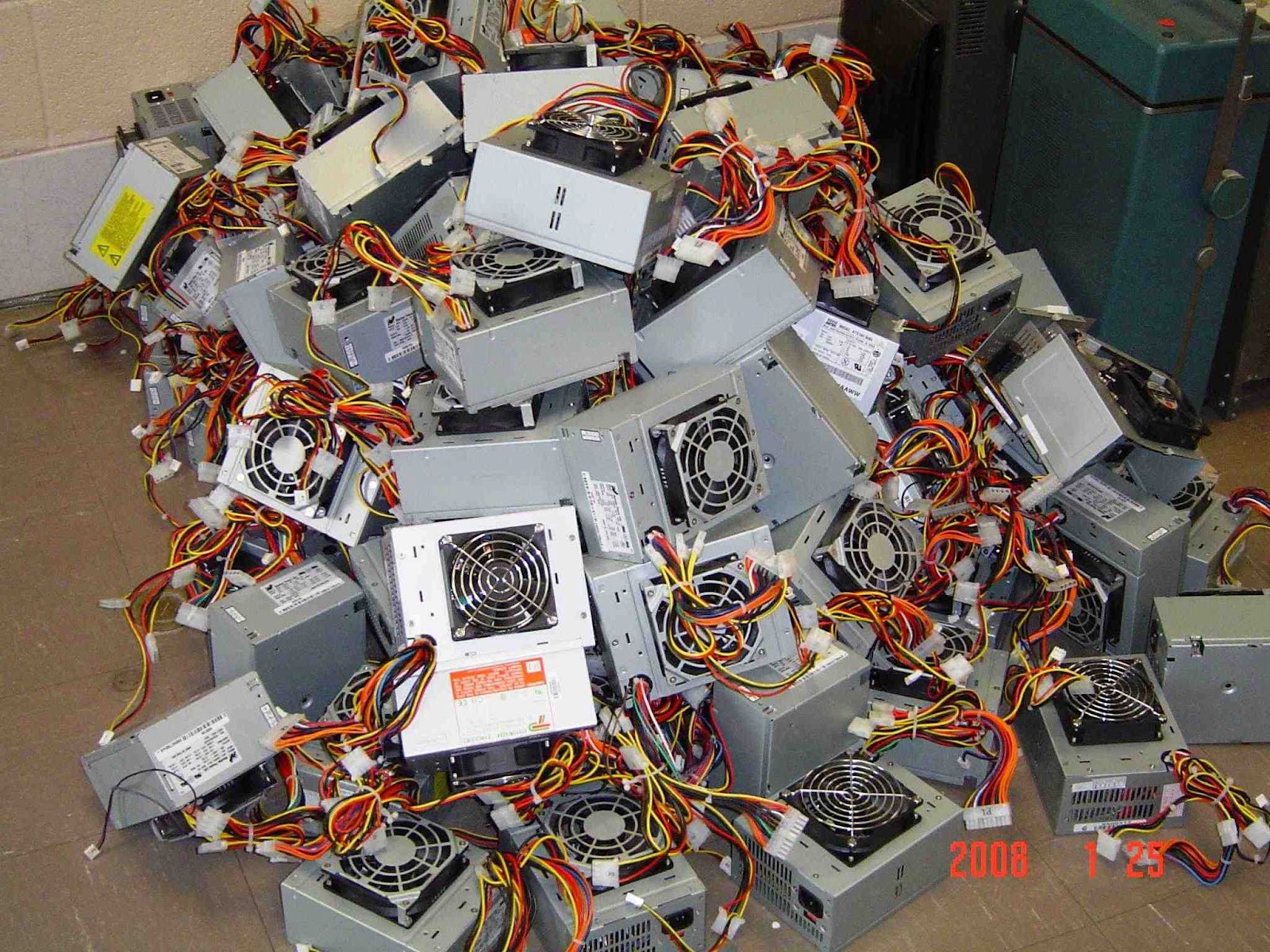
 I’ve noticed a few spirited discussions regarding modifying computer power supplies for use with Amateur Radio equipment. On the surface it seems as though they supply the perfect solution: Inexpensive, high current, regulated 12V DC supplies for a fraction of the cost of specialized amateur equipment. Is it really is as straight forward as lopping off a molex connector and replacing it with an Anderson Powerpole?
By design PC power supplies are designed to output a fairly well regulated 3.3V & 5V to the PC motherboard and 12V to the motherboard, fans and hard-drive motors. Modern units are typically rated anywhere from 75W to 1200W which should be a measurement of the output power available from all the 3.3, 5 and 12 volts. Since this isn’t a lab grade power supply you can expect marketing hyperbole has perhaps inflated the power output figures.
Back when my job was to build PCs I had an issue with a server not being able to start its complete complement of disk drives. When I opened the case I found a 300W desktop supply board had been used in place of the 800W board … sometimes you don’t even get what you pay for!
Before you convert your first PC power supply there are two issues that may, or may not, cause a problem depending on your unit.
The first is load regulation or the ability of the power supply to maintain its rated voltage under load. If the output voltage drops too far your rig will shutdown, distort or fail to provide its rated output power.
The second issue is due to the high frequency switching circuits used in switch mode supplies. Depending on the individual power supply there can be adequate to no filtering to prevent radio frequency interference being broadcast to your receiver. Toroids on the input and output lines can help to reduce interference.
 Because of construction differences between models and even between batch numbers for the same model you can never be certain how the power supply you purchase, or recycle, will perform. For the most part people’s experiences have been positive but I have heard of power supplies that were unusable because of RF interference or such poor load regulation that the 12V rail dropped to 11V under load.
Without a motherboard presenting a load and supplying the power-on signal there are a few changes that need to be made to the power supply. Modern power supplies will not enable the 12V output unless the power-on wire is grounded and a load should be placed on the 5V line to help with regulation. Additionally there is usually an adjustment that can be used to raise the voltage above 12V
The following links detail the steps required to convert a PC supply for use with amateur radio equipment. Whether this represents a good investment of your time will depend on your desire to do-it-yourself and the quality of the power supply you begin with. I’ve heard strong opinions either way but I’ll just say that, if luck favors you, you’ll save some money and learn a few new skills in this exercise.
Computer Power Supply Converted for Ham Use
CONVERTING COMPUTER POWER SUPPLIES (Advanced with theory)
Converting Computer Power Supplies to stabilized 13.8 V DC 20 A
EICO Model 625 Tube Tester
I attended the Greater Houston Hamfest and as I walked past the tables of equipment I wondered if interest in vacuum tube equipment was starting to wane. Compared to the last few years the prices of collector quality gear had held steady but parts and restorable gear seemed to be going for less. I’d like to know your thoughts if you’ve noticed trends one way or the other.
I was happy to pick up a EICO Model 625 tube tester for $15. It is in good condition and appears to work well. The roll of settings for each tube is in good condition and a little searching on the internet supplied settings for older tubes like the number 78 in the picture below.
 |
| EICO Model 625 Tube Tester with a number 78 tube |
The EICO 625 is not a top of the line tester but it does basic tests and will let you know if a tube is functioning and an idea of the life left in it. It was sold in kit form for $34.95 in 1958 which is roughly equivalent to $274 in 2012.
 |
| Inside the EICO 625 from diyaudioprojects.com |
The EICO 625 is fairly unique in having its own 6H6 diode tube to rectify the 30V filament voltage. It provides DC for the neon short-indicator bulb. If the tube is suspected of having a short then there is a fairly comprehensive series of tests than can be administered to isolate shorted elements.
 |
| EICO Model 625 circuit diagram |
Here is the complete TUBE TEST DATA 1/1/78 for the EICO Model 625 Tube Tester
Excellent information on servicing and calibrating your Classic emission tube tester.
DIY Magnetic Loop Antenna – Part 3
Well, I finally have had time to sit down and put together part three of the DIY Magnetic Loop Antenna, sorry it has taken so long!
This post will cover building and coupling the loop to your transceiver. After reading through posts one and two you should have a good idea of the parts you’ll use and the physical dimensions of the main loop.
DIY Magnetic Loop Antenna – Part 1
DIY Magnetic Loop Antenna – Part 2
Most magnetic loops have the capacitor at the top of the main loop and the gamma match or matching loop at the bottom, this arrangement avoids running the feed-line through the center of the antenna.
You can assemble the main loop from continuous copper tube or from eight straight sections and 45 degree joiners. Make sure you have a blow torch or propane torch to solder the joints as you’ll need more heat than a soldering iron can supply. Whichever way you decide to build the main loop make sure that all joints are soldered or clamped as securely as possible, you want the lowest resistance possible to avoid your output power turning into heat. Other materials can be used for the main loop such as aluminium or low loss coax but copper pipe is easy to work, has low resistivity and available from just about every hardware store.
To construct the frame of the antenna you can use PVC pipe. It is a cheap and relatively sturdy building material and is available in a range of thicknesses, just about any hardware store will stock a wide selection of fittings. It insulates well and can be glued once you are sure your project is in its final form.
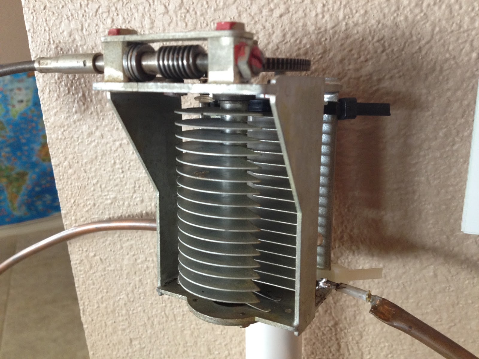
Once the main loop is constructed you’ll need to connect your capacitor to the two ends of the pipe at the top of the loop. Depending on the capacitor you may want to solder tags to the ends of the loop so they will be easier to attach. Copper pipe is a great conductor of heat and takes a lot to heat up and solder while it is not advisable to apply the same amount of heat to your capacitor.
It is also a good idea to attach the capacitor to a solid support so that the connections are not under strain.
The main loop and the capacitor forms the resonant circuit of the magnetic loop antenna.

To couple the main loop to your transceiver and match the expected 50 Ohms impedance you can use one of two methods. Probably the easiest is to use is a loop of insulated wire 1/5 the circumference of the main loop. The smaller loop is placed at the bottom of the main loop and can be shifted around to provide the best match. If you have an antenna analyzer you’ll be able to set it to the desired frequency, tune the variable capacitor for resonance and then move the small matching loop around till you have achieved close to 1:1 SWR. If you don’t have an antenna analyzer you can tune the capacitor for the greatest received noise and then on low power tweak the capacitor and move the coupling loop around for best SWR. Do NOT touch the loop while it is transmitting, use a wood or plastic rod to make adjustments as there are high voltages and intense RF fields near the loop.
An alternative to the coupling loop is the gamma match. The shield of the coax feed cable is connected to the base of the main loop while the inner conductor is connected to a point approximately 1/5 of the circumference around the loop. Its a good idea to use stiff wire (large gauge) for the gamma match as it can be critical of the position and orientation and once you have it in the right position you won’t want to move it again.
It would be preferable to have the ability to remotely tune the loop. A motor with a reduction gear could be used to move the variable capacitor but because the point of resonance is very narrow there should be a way of slowing the motor down. A simple control circuit using variable pulse width modulation could be used to slow the motor down while still retaining enough torque to move the capacitor. Whatever method is used to move the capacitor it should be well insulated from the other components of the antenna. Several thousand volts are generated on the MLA and care should be taken to ensure they don’t find their way onto control leads and back into the shack. Control leads should also be wrapped around toriod inductors as they leave the near field of the antenna to reduce the possibility of RF travelling along them.
With a SWR bridge and microcontroller you could build a fully automatic tuner that swept through the range of the tuning capacitor when the SWR rose above a defined limit indicating that the transmit frequency had changed.
With a little creativity and knowledge you could have an impressive MLA the equal of multi-thousand dollar military style units.
Hopefully this has given you some ideas for constructing your own loop antenna. Regardless of if you go top-of-the-line and buy a vacuum variable or build for economy and QRP you’ll have a compact, useful and unique antenna.
What has been happening?
Anyone looking at my blog could be forgiven for thinking that I had dropped off the face of the earth for a while, has nothing been happening in my world?
Well, the answer is that a LOT has been happening and all at once. My daytime job has become busier and there have been several non-radio projects at home that needed to be completed. All this has kept me away from Amateur Radio blogging even though I have spent more time on the computer than usual.
In between projects I did manage to stumble across this video of Rear Admiral Grace Hopper explaining just how “long” a nano-second is and what it looks like. This has relevance to radio as we’re usually well aware of frequency and wavelength but don’t usually spend too long thinking about speed.


