Author Archive
 The KARS 2012 Summer Field Day Video
It took a little while but I finally got the video for the Katy Amateur Radio Society summer field day together. I didn’t shoot as much video or as many photographs this year as I actually spent time a fair amount of time operating for a change!
Hopefully it will still be an entertaining, if short, reminder of those two days in June.
Katy Amateur Radio Society – Summer Field Day 2012 from Owen Morgan on Vimeo.
The unfortunate & epic saga of the perfect military radio
 |
| The long awaited but ultimately unwanted GMR radio |
As my day job starts to include more long term projects & project management I was particularly intrigued by an article in arstechnica.com. The article is, “How to blow $6 billion on a tech project“, although the title may be more inflammatory than technically accurate.
The article covers the 15 year development of an advanced & unified military radio communications system that suffered from multiple issues including scope-creep & a rapidly changing underlying technology.
If you are involved with a group that is working to develop a product or service you’ll really get something from this article. If you interested in radio systems, military or otherwise, you’ll find this interesting as well.
Its hard to image the frustration people suffer when contributing to a project that is mismanaged unless you have been there yourself. I hate to think of the wasted effort that resulted when people found out How to blow $6 billion on a tech project
The Johnson 275W Matchbox Antenna Tuner
I had purchased a Johnson Matchbox from an estate a while back & decided that while I was home with the flu I would open it up and check on its condition.
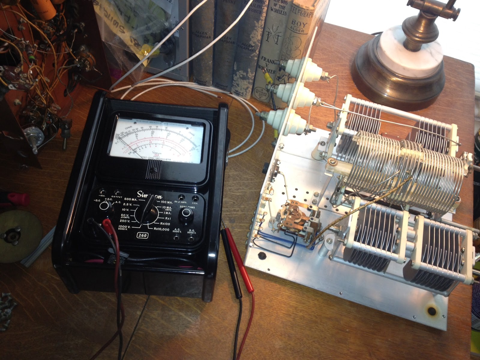 The Johnson Matchbox is found most commonly in two versions, the smaller “275W” unit and the larger Kilowatt Matchbox. Why did I use quotation marks around 275W? Well, these units were manufactured back in the good old days when men were men and transmitting voice meant using AM, not single side band. The conservative rating of 275W of AM translates into roughly 800W of peak SSB (Not really but close enough so you get the idea)
Unlike many who own a Matchbox I was hoping to keep it 100% original and that it would contain all its original components, including the antenna change-over relay and wiring for the high-impedance receiver antenna connections. I plan to use this Johnson Matchbox with a Heathkit AT-1 transmitter and Hallicrafters SX-25 receiver so the inclusion of an antenna change over relay and 300 Ohm receiver connections will make life MUCH easier. Something I didn’t realize until I had the unit apart (There are a LOT of screws holding this thing together) is that there is also a receiver control contact on the relay to break HT and mute the receiver during transmit which will work with my SX-25.
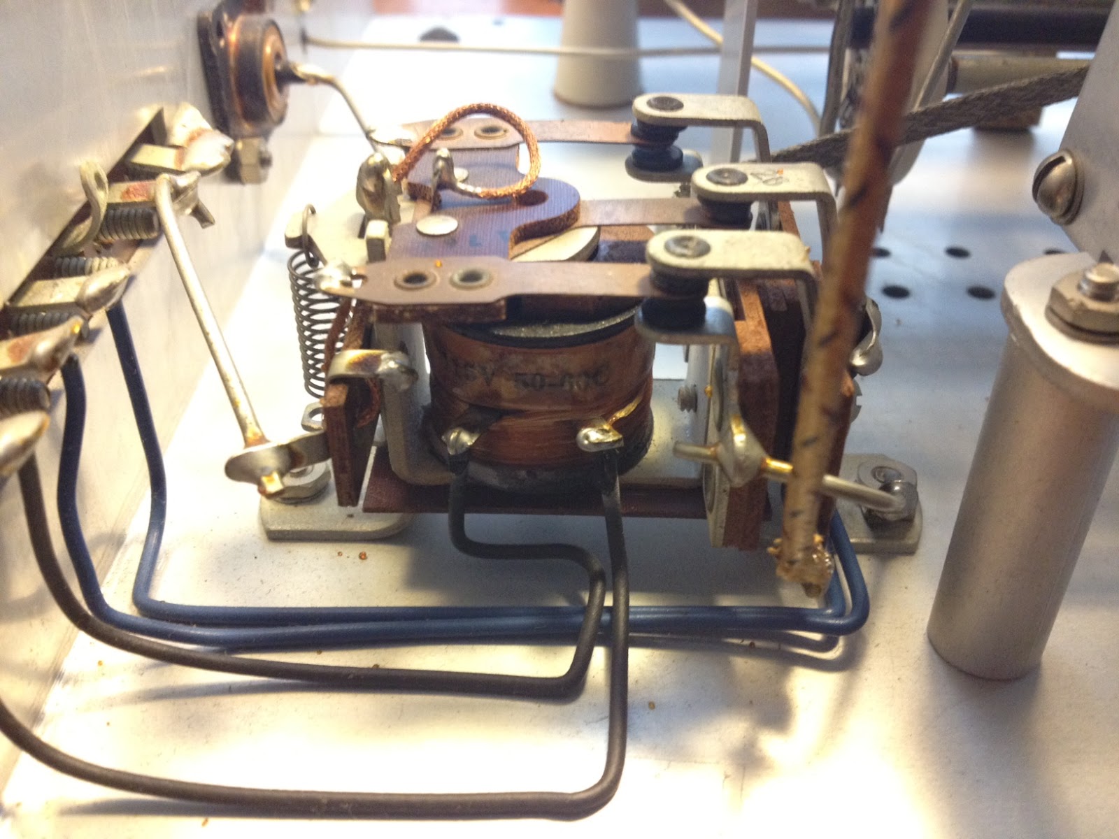 An initial inspection showed that the only modification was a small piece of plastic wedged into the relay contacts that held the relay in the transmit position. It was easily removed and the relay coil and contacts tested for continuity. The contacts seem a bit dirty which, from the little I have read online, seems to be a common problem.
Once the relay contacts and band-switch are cleaned I will button the unit back up and connect it to the loop antenna I have recently run around the eaves of the house. The loop has been a huge improvement to the long-wire and magnetic antennas I have run in the past, at least as far as reception goes … but that is a topic for another post.
Vacuum tubes could revolutionize computer chips?
No, I’m fairly sure I haven’t lost my mind … that really is the right headline.
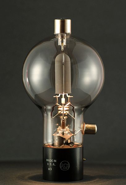 According to a resent paper published in the American Institute of Physics, nanoscale vacuum “tubes” manufactured using conventional chip making techniques have operated at frequencies as high as .46 THz.
Dr. Meyya Meyyappan, Director at the Center for Nanotechnology at the NASA Ames Research Center, has highlighted the advantages of nanoscale vacuum devices which include resistance to hard radiation and significantly improved operating frequencies.
![]() The increased operating frequency comes about because of the speed at which electrons travel through different materials. The speed of electron travel through silicon is comparatively slow, through graphine it is approximately 100 times faster and through a vacuum it approaches the speed of light.
The increased operating frequency comes about because of the speed at which electrons travel through different materials. The speed of electron travel through silicon is comparatively slow, through graphine it is approximately 100 times faster and through a vacuum it approaches the speed of light.
While the cavity is not technically a vacuum it contains so few atoms of any other material, such as oxygen, it is functionally the same. This also gives the vacuum nanoscale device an advantage in space where hard radiation can disrupt an electron’s travel through silicon leading to errors or sometimes permanent failure.
Dr Meyyappan estimates that vacuum nanoscale components will run ten times faster than the best conventional silicon chips and who knows what advances the future will hold. Faster chips will aid in signal processing and more capable software defined radios.
Do you want to monitor every CW & PSK31 transmission on the 40M band at once? With a vacuum “tube” rig you may be able to!
Something old, something new.
Something old …
As a young boy in Australia my two favorite hangouts were my grandfather’s shed or practically anywhere that electronics were sold. The two largest electronic component retailers in my home town were Tandy (Radio Shack) and Dick Smith Electronics. They both sold kits, tools, ‘100 in 1 Labs’ and other assorted gear but Dick Smith eventually became known as the experimenters store due to their greater range.
 |
| Original Radio Shack calculator |
If you would like to make one of these yourself then Adafruit Industries has created a PDF document you can print and cut out for create your own resistor value calculator.
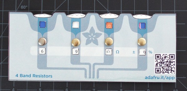 The PDF file is available from Adafruit Industries or a copy is also here. Once you print it out, a little cutting and folding should produce something like the example of the right. The Adafruit design uses brass paper fasteners (remember those?) but any fastener could be used that would allow the wheel inside to rotate freely. It would be best to print on heavy card stock if you have the ability as it will give the calculator some strength.
Something new …
If you happen to have one of those new fangled iDevices you can download Circuit Playground. It has a few more features than the old Radio Shack calculator and looks great on the iPad.
More features are being added but the list at the moment includes:
- Decipher resistor & capacitor codes with ease
- Calculate power, resistance, current, and voltage with the Ohm’s Law & Power Calc modules
- Quickly convert between decimal, hexadecimal, binary or even ASCII characters
- Calculate values for multiple resistors or capacitors in series & parallel configurations
- Store, search, and view PDF datasheets
- Access exclusive sneak peaks, deals & discounts at Adafruit Industries
You can download it from the iTunes Store or, if you have an Android, you can check out ElectroDroid for similar functionality.
As time goes on there are more and more useful utilities available for electronic experimenters on iOS and Android devices. Since more and more equipment today is becoming computerized do iOS and Android devices represent the future of test equipment?
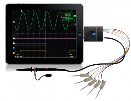 |
| iMSO-104 iPad Oscilloscope |
The further adventures of the Heathkit AT-1
Work has been conspiring to eliminate my spare time but I was able to spend a few hours over the Easter holiday to clean up the shack and make space to put the Heathkit AT-1 on the desk again. I have been able to spend a little time going over parts that need to be replaced and making a list.
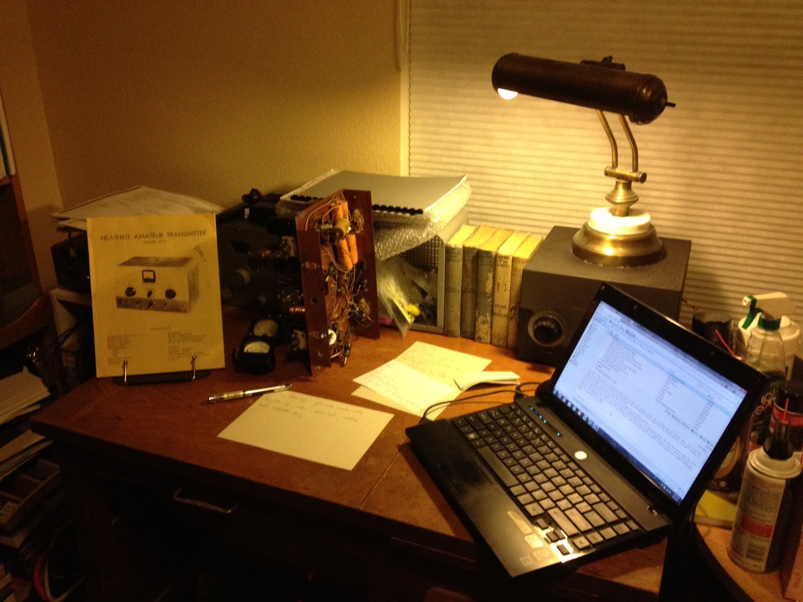 |
| The Heathkit AT-1 chassis with case and VFO-1 behind. |
There doesn’t seem to be any show stoppers although the wafer of the meter switch has broken in two and will need to be repaired. If I’m not able to repair it then thankfully it is fairly simple and replacement rotary switch can be substituted.
This isn’t going to be a museum quality restoration but the changes that were made to this transmitter in the past were sensible and if left in place are representative of period modifications. The original meter for example was not the highest quality and a Western or Simpson replacement would be an improvement. The original slide switches have been replaced with period snap-toggle switches which are also an improvement over the original.
The Heathkit VFO-1 however has been modified for grid-block keying which is a significant departure from the original and I plan to revert it back to cathode keying. Although a technical improvement it is not in keeping with the original design and needs to be undone. Everyone will have their own opinion but I think if I wanted modern circuits I’d get a more modern rig, so the VFO-1 will be returned to stock.
Hopefully I can carve out a bit of time here and there to work on this and slowly return it to working condition.
Now I understand – Measuring capacitance with a micro-controller
The excellent article by Rajendra Bhatt explains not only how capacitance can be measured but also how a micro-controller can be interfaced to an analog circuit to create a useful piece of test equipment.
 |
| Capacitance meter by Rajendra Bhatt |
I found the explanation of the RC time constant method of measurement as interesting as the micro-processor project itself and congratulate Raj on demonstrating a practical and workable real-life example of what can normally be a dry textbook subject.


