 200 Ohm Feed Point Off-centre Fed Dipole

The off-centre dipole installed on Field Day 2010 (photograph and copyright of Chris Weisner, VA3SM)
As I mentioned in the earlier Field Day 2010 report, the CUARC group built two antennas for the event. In this post I will describe the first one of these, an off-centre fed dipole.
The common place for the feed point of the off-centre fed dipole is at a 1/3 : 2/3 split in the arms. This has the advantage of providing low SWR (with a 4:1 balun) at even harmonic frequencies, such as 20m and 10m for an antenna cut for the fundamental frequency of 40m (around 66ft). Whereas a centre-fed dipole will only have the odd harmonics which for a 40m (7MHz) dipole is 15m (21MHz).
Rather than use the traditional off-centre length split of 1/3 : 2/3 for our Field Day antenna, it was decided to follow the design proposed by Richard Formato, K1POO, in two technical correspondences published in QST 1,2 and followed up with further article with by Dale Gaudier, 3. In this design the feed point is moved closer to the 1/6 point on the short arm, the advantage being stated in the articles that you should get a 200Ω feedpoint there and so a low SWR on 40m, 20m, 15m and 10m bands when using a 4:1 balun, with no need for an antenna tuner unit. The emphasis on the 15m band is intentional as a low SWR on that band is not usually possible with an off-centre fed dipole with the feed at 1/3 : 2/3 and a 4:1 balun. Four bands on one 69 foot wire antenna with no tuner looked very attractive for Field Day.
The antenna was cut carefully prior to Field Day and the end insulators were added. When cutting the antenna the length measurement included the ‘pig-tail’ connections that I have on the 4:1 balun. The diagram below shows the arrangement of the antenna.
On the day the antenna was installed between two trees at about 35ft off the ground. While the second antenna was being constructed (to be featured in a later post) its SWR was measured with my Autek RF-1 antenna analyzer. The results were taken by Maria, VA3MMI and Gil, VE3JRY and are tabulated below.
_______________________________________________
Band (m) 2:1 VSWR Range (MHz) Minimum VSWR
40 3.1 : 1 (at 7.38 MHz)
20 13.29 – 14.65 1.4 : 1
15 21.20 – 22.31 1.5 : 1
10 27.78 – 29.25 1.7 : 1
_______________________________________________
The overall results were very pleasing, although the 40m band was a little disappointing. This higher than expected SWR on 40m was also encountered by Dale, M0AOP/K4DG, and was reported 3 by him to be due to the severe imbalance in the antenna, so requiring a choke balun to remove the stray RF on the coax. We did not try a choke balun, since we were unlikely to operate on 40m, that was another station’s band of operation. However we had an antenna tuner unit if we needed to try and tame the SWR. It was very good to see the SWR profile observed in reference 3 was repeatable.
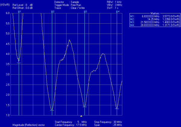
On Sunday morning Maria, VA3MMI, returned with a portable analyzer borrowed from work and did a sweep analysis. The response is below and markers have been inserted to show the minimum SWR associated with the bands. Thanks goes to Maria for the measurement and the plot.
It would be interesting to remeasure the SWR response again with a choke balun in place. I expect the SWR will drop below 2:1 within the 40m band as found by the author of reference 3. If this does happen then four bands and no tuner needed makes this antenna one for serious consideration on HF. Even without a low SWR on 40m the antenna offers three bands and it performed well on 15m and 10m for us on Field Day.
As a final note, I should reiterate the warning by Dean Straw, N6BV, at the end of reference 1 where he warns about using the antenna on 30m, 17m or 24m, as a very high SWR could damage the balun at the feedpoint.
References
1. “Improved Feed for the Off-Centre-Fed Dipole” R. A. Formato, K1POO, Technical Correspondance, QST, May 1996 p76.
2. “Off-Centre-Fed Dipole Comments, Part 2″, R. A. Formato, K1POO, Technical Correspondance, QST, October 1996 pp72-73.
3. “Choke the OCFD” D Gaudier, M0AOP/K4DG, Technical Correspondance, QST, September 1997, pp82-83.
Note: all three of the above papers are collected together in “More Wire Antenna Classics Volume 2″ ARRL, (1999).
The Field Day photographs above are from the Ottawa Valley Mobile Radio Club’s photo gallery.


If you use the formula from http://ham.stackexchange.com/questions/95/how-does-moving-a-feedpoint-off-center-in-a-dipole-affect-the-resonant-frequency you will see that the dimensions given produce a 100 ohm feed point, not a 200 ohm one.