Posts Tagged ‘VK4YB’
 LF / MF News From Monitor Sensors

A note from Roger, VK4YB of Monitor Sensors, reports some interesting news.
You might recall that his company manufactures a very versatile and well-engineered 630m transverter which was used at both ends of our two 630m JT9 contacts last year during the fall equinox propagation peak between North America and down-under.
Roger now reports that Monitor Sensors will be producing a new 2200m transverter, with all of the bells and whistles found on the 630m unit which has proven to be a real workhorse.
Monitor Sensors 2200m Transverter
The Monitor Sensors TVTR2 2200m Transverter enables any Amateur Radio Station, equipped with a conventional HF transceiver, immediate, all mode, access to the new 135.7-137.8 kHz, 2200m band.
The receiver design incorporates a 7pole Chebyshev filter, 3kHz wide roofing filter and a 5 pole Chebyshev filter in cascade before the double balanced, commutating mixer, fed by an ultra stable, temperature compensated, extremely low phase noise, MEMS local oscillator. The mixer is followed by a Chebychev band pass filter into an ultra linear, low noise, current feedback, IF amplifier. The receiver noise floor, in a 500Hz bandwidth, is -125 dBm and yet the onset of compression is not reached until +11dBm. A front end 20dB attenuator can be switched in for even higher signal handling. Overall receiver gain is set to +6dB, or -14dBm with attenuator in.
The transmitter input circuit incorporates a 0-14 dB switched step attenuator to prevent over driving. The same mixer and local oscillator are used on the transmit side. The PA uses 6 rugged lateral FETs in class AB push-pull to easily achieve the 50 watts rated output. Lateral FETs are inherently linear and thermally stable. The transmitter can be run at full power, indefinitely, into a dead short or open circuit without any danger of damaging the FETs. Transmit-receive switching is automatic with user selectable VOX delay. Alternatively the PTT line may be used.
The transverter employs extensive and accurate metering. Power input and output, SWR, Frequency, Attenuation in use, Temperature, Supply Voltage, Current and Resistance are displayed.
Transmission is inhibited if carrier frequencies outside the 135.7-137.8 kHz band are detected. A tuning screen may be selected which displays SWR in digital and graphical form for easy antenna adjustment. The menu system is self explanatory and users report no manual is needed, although one is supplied. A USB socket is provided for future code upgrades (free of charge) from the Monitor Sensors web site.
The transverter has been designed for the best possible protection against accidental mishaps. It will survive reverse polarity supply and the injection of 100 watts of HF into any of its ports whether in transmit or receive mode. If supply current exceeds 25 Amps, the supply is cut in 3 microseconds. This electronic breaker can be reset by simply switching off and on again. The transmitter will shut down in the unlikely event that the internal heat sink reaches 90°C. The cooling fan is under the proportional control of the microcomputer and begins operation above 35°C. Any unusual operation will cause the screen to turn red and an appropriate warning will be displayed.
TVTR2 Specifications
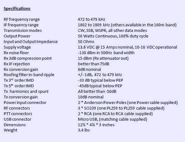
RF frequency range 135.7 to 137.8 kHz
IF frequency range 1805.7 to 1807.8 kHz (others available in the 160m band)
Transmission modes CW, SSB, WSPR, and all other data modes
Output Power 50 Watts Continuous, 100% duty cycle @13.8V supply
Input and Output Impedance 50 Ohms
Supply voltage 13.8 VDC @ 15 Amps nominal, 10-16 VDC operational
Rx noise floor -125 dBm (500 Hz bandwidth)
Rx 3dB compression point +15 dBm (Rx attenuator out)
Rx IF rejection better than 75dB
Rx conversion gain +6dB nominal
Roofing filter in-band ripple +/- 0.5dB
Tx 3rd order IMD -33 dB below PEP, typical at 50W output
Tx 5th order IMD -45dB below PEP, typical at 50W output
Tx harmonics and spurii All better than -50dB
Tx conversion gain +10dB nominal
Power input connector 2 * Anderson Power Poles (one Power cable supplied)
RF connectors 3 * SO239 (one PL259 to PL259 cable supplied)
PTT connectors 2 * RCA (one RCA to RCA cable supplied)
USB connector Micro B USB, (matching cable supplied)
Dimensions 12½ * 4¼ * 3 inches, 320 * 120 * 76 mm
Weight 3.4 lbs, 1.6 kg
In addition to the transverters, Monitor Sensors will also be manufacturing solid state amplifiers for both the 2200m and 630m bands with power levels at around the 450W output level. Like the transverters, these will be 'linear' devices as well. It is possible that a duo-band amplifier will also eventually be produced.
It will be interesting to see if any other new gear becomes commercially available from other manufacturers once the LF / MF ham bands are introduced in the U.S.A. , something that is expected to happen fairly soon.
LF / MF News From Monitor Sensors
A note from Roger, VK4YB of Monitor Sensors, reports some interesting news.
You might recall that his company manufactures a very versatile and well-engineered 630m transverter which was used at both ends of our two 630m JT9 contacts last year during the fall equinox propagation peak between North America and down-under.
Roger now reports that Monitor Sensors will be producing a new 2200m transverter, with all of the bells and whistles found on the 630m unit which has proven to be a real workhorse.
Monitor Sensors 2200m Transverter
The Monitor Sensors TVTR2 2200m Transverter enables any Amateur Radio Station, equipped with a conventional HF transceiver, immediate, all mode, access to the new 135.7-137.8 kHz, 2200m band.
The receiver design incorporates a 7pole Chebyshev filter, 3kHz wide roofing filter and a 5 pole Chebyshev filter in cascade before the double balanced, commutating mixer, fed by an ultra stable, temperature compensated, extremely low phase noise, MEMS local oscillator. The mixer is followed by a Chebychev band pass filter into an ultra linear, low noise, current feedback, IF amplifier. The receiver noise floor, in a 500Hz bandwidth, is -125 dBm and yet the onset of compression is not reached until +11dBm. A front end 20dB attenuator can be switched in for even higher signal handling. Overall receiver gain is set to +6dB, or -14dBm with attenuator in.
The transmitter input circuit incorporates a 0-14 dB switched step attenuator to prevent over driving. The same mixer and local oscillator are used on the transmit side. The PA uses 6 rugged lateral FETs in class AB push-pull to easily achieve the 50 watts rated output. Lateral FETs are inherently linear and thermally stable. The transmitter can be run at full power, indefinitely, into a dead short or open circuit without any danger of damaging the FETs. Transmit-receive switching is automatic with user selectable VOX delay. Alternatively the PTT line may be used.
The transverter employs extensive and accurate metering. Power input and output, SWR, Frequency, Attenuation in use, Temperature, Supply Voltage, Current and Resistance are displayed.
Transmission is inhibited if carrier frequencies outside the 135.7-137.8 kHz band are detected. A tuning screen may be selected which displays SWR in digital and graphical form for easy antenna adjustment. The menu system is self explanatory and users report no manual is needed, although one is supplied. A USB socket is provided for future code upgrades (free of charge) from the Monitor Sensors web site.
The transverter has been designed for the best possible protection against accidental mishaps. It will survive reverse polarity supply and the injection of 100 watts of HF into any of its ports whether in transmit or receive mode. If supply current exceeds 25 Amps, the supply is cut in 3 microseconds. This electronic breaker can be reset by simply switching off and on again. The transmitter will shut down in the unlikely event that the internal heat sink reaches 90°C. The cooling fan is under the proportional control of the microcomputer and begins operation above 35°C. Any unusual operation will cause the screen to turn red and an appropriate warning will be displayed.
TVTR2 Specifications
RF frequency range 135.7 to 137.8 kHz
IF frequency range 1805.7 to 1807.8 kHz (others available in the 160m band)
Transmission modes CW, SSB, WSPR, and all other data modes
Output Power 50 Watts Continuous, 100% duty cycle @13.8V supply
Input and Output Impedance 50 Ohms
Supply voltage 13.8 VDC @ 15 Amps nominal, 10-16 VDC operational
Rx noise floor -125 dBm (500 Hz bandwidth)
Rx 3dB compression point +15 dBm (Rx attenuator out)
Rx IF rejection better than 75dB
Rx conversion gain +6dB nominal
Roofing filter in-band ripple +/- 0.5dB
Tx 3rd order IMD -33 dB below PEP, typical at 50W output
Tx 5th order IMD -45dB below PEP, typical at 50W output
Tx harmonics and spurii All better than -50dB
Tx conversion gain +10dB nominal
Power input connector 2 * Anderson Power Poles (one Power cable supplied)
RF connectors 3 * SO239 (one PL259 to PL259 cable supplied)
PTT connectors 2 * RCA (one RCA to RCA cable supplied)
USB connector Micro B USB, (matching cable supplied)
Dimensions 12½ * 4¼ * 3 inches, 320 * 120 * 76 mm
Weight 3.4 lbs, 1.6 kg
In addition to the transverters, Monitor Sensors will also be manufacturing solid state amplifiers for both the 2200m and 630m bands with power levels at around the 450W output level. Like the transverters, these will be 'linear' devices as well. It is possible that a duo-band amplifier will also eventually be produced.
It will be interesting to see if any other new gear becomes commercially available from other manufacturers once the LF / MF ham bands are introduced in the U.S.A. , something that is expected to happen fairly soon.
630m VK’s Light-Up North America
It seems that all of my blogspots of late have focused on 630m propagation ... but what has been happening down there recently has been both amazing and somewhat unexpected. With the growing number of active stations listening and transmitting, the band's propagation capabilities and mysteries are quickly revealing themselves.
Last night was a great example but perhaps the WSPRnet prop map illustrates this best.
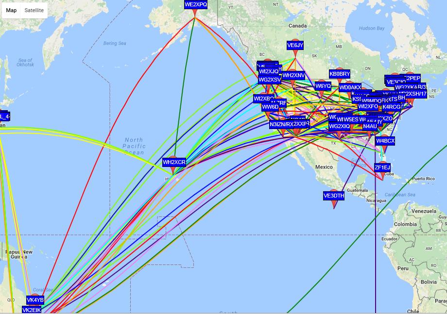 |
| courtesy: http://wsprnet.org/drupal/wsprnet/map |
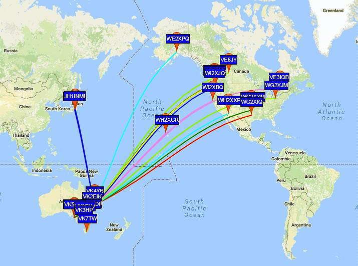
Particularly striking was the long haul propagation from VK to North America, with northernmost VK4YB leading the pack. His 90 watt signal made it all the way to VE3IQB, near Ottawa as well as to NO3M, in Pennsylvania! To provide further hope to those that have little room for big receiving antennas, VE3IQB uses a typical small active e-probe antenna, 20' above ground!
 |
| courtesy: http://wsprnet.org/drupal/wsprnet/map |
 |
| courtesy: http://www.swpc.noaa.gov/ |
I'm theorizing that Roger's signal was arriving today at much lower angles than normal, evidenced by its far-reaching east coast reception and the fact that it couldn't get over my 600' local obstruction to the west. I've always believed that it takes higher angled signal arrival for me to hear Roger and today's events seem to support this.
Exactly what would cause this to be the case, I'll leave to the experts but I imagine that the sudden surge in geomagnetic activity played a significant role in today's very different propagation paths.
Roger was not the only VK lighting-up the map today. A much more detailed account of all the action can be found on the KB5NJD's daily 630m report here ... all very inspirational and hopefully enough to spur even more new activity on the MF band.
Why not give a listen and see what you can hear?
First VK-VE 630m Contact!
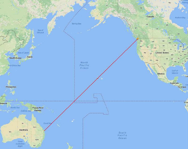 |
| courtesy: https://www.google.ca/maps |
Shortly before sunrise yesterday morning, VK4YB (Roger) and I were able to work each other on 630m ... 475.300 kHz to be exact!
This is the first-ever QSO between North America and Australia on the relatively new 630m MF band. As well, at 11,802km, it presently represents the furthest two-way contact on this band, worldwide ... but I don't expect this record will last very long once the U.S. gets the band as I believe Roger's fine station is very capable of reaching much further afield.
Our contact on JT9, the WSPR QSO mode, was made at 1319Z, about 30 minutes before my local sunrise with the sky surprisingly bright. Blog readers will know that Roger and I have been carefully watching the pre-dawn Trans-Pacific propagation path for the last week. I have been checking-in with him via the ON4KST LF/MF chat page every morning at around 0345 local time at which point a decision is made ... "get out of bed and head for the shack" or "go back to sleep". Each morning's (or in Roger's case, each evening's) propagation quality is assigned a code number by Roger, based upon what he has been hearing during the early evening hours ... a '6' or below is 'sleep-time', a '7' is a 'you decide' while an '8' or above is 'get your butt moving'.
Yesterday, Roger issued a 'code 7' but as I joked with him later, I think he tricked me as it seemed more like a '6.5' from this end! Trans-Pacific conditions were very good about 500 miles to my south but seemed to drop-off quickly much further to the north. I also need to get over a significant obstruction immediately to the SW of me and in line with Roger. That's me directly at the base of the hill on the right while the remaining peaks are on nearby Saltspring Island and then Vancouver Island before reaching the open Pacific.
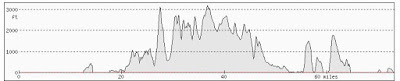 |
| courtesy: http://www.heywhatsthat.com/profiler.html |
I believe this requires some enhancement of high-angle arrival (and departure) which often occurs around dawn due to a short period of ionospheric 'tilting'. This is often noted by topband operators near their local sunrise, who regularly observe stronger signals on low (cloud-warming) dipoles than they do on their normal large (low-angle) verticals or beverage antennas.
We enjoyed significantly stronger conditions a week ago, but unlike Thursday when I could run at full 5W EIRP, I was only able to generate a little less than 1W EIRP at the time. So far, this week, conditions have been improving steadily each day, from a 'code 3' to a 'code 7'. Hopefully they will continue to improve and we can do it all over again sometime soon.
With my new antenna / transverter / amplifier relay control box working nicely, it seems that Roger and I can now fully take advantage of TP propagation from 'mediocre' to 'excellent' but we have yet to see just how good it can get.
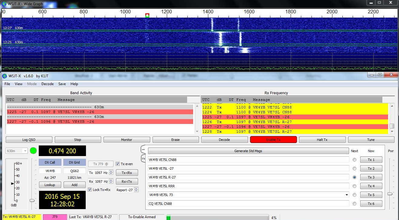 |
| Roger's signal is at +1100Hz |
It is hoped that our contact will inspire new interest among amateurs worldwide and particularly in North America. If you are planning a station, it seems that the main mode of two-way communications will be CW or JT9 ... a simple transverter would allow both modes as well as the use of the WSPR beacon mode. More information may be found here as well as in earlier 630m blogs.
See also: http://www.arrl.org/news/a-record-breaker-on-630-meters
630m Early Morning Skeds
This past week I was eventually able to mate my W1VD frequency doubler with my 630m FET amplifier and run some higher powered tests on 630m WSPR and JT9 modes.
Up until this time, I have been limited to about 1/2 W EIRP but using the amplifier allows me to get to the 5W EIRP limit. I have been using the VK4YB transverter's 475kHz reduced output of 1W and driving the doubler previously built as part of a transverter project. The doubler produces a nice 950kHz squarewave to drive my amplifier's divide-by-two flip-flop input circuit which in turn produces the dual antiphase outputs needed to drive the push-pull switching FETs in the final amplifier. Being a linear transverter, when used alone at 70W, it will run any mode that the IC756 ProIII will produce such as SSB, WSPR etc, but my switching FET amplifier is class-D, non-linear, which limits it to non-linear modes such as CW, WSPR and JT-9, the most popular modes on 630m.
A few days ago, VK4YB and I ran our first 630m sked on JT9 as conditions looked favorable. Unfortunately, this was before I had my transverter / antenna switching system completed so I was limited to the barefoot transverter at ~ 1/2W EIRP. Using a transverter to drive an external amplifier means the antenna must be switched between the amplifier output and the transverter input in addition to switching the transverter's output between the antenna and the amplifiers input. I'll post details of my switching system, and inexpensive but power-capable relays, in an upcoming blog as there are probably many 630m operators planning on doing something similar.
Thanks to Roger's huge antenna, his 90W signal was making it through well enough on this end but he was not able to decode anything from me.
1109 -26 0.3 1098 @ VE7SL VK4YB QG62
1111 -28 0.3 1098 @ VE7SL VK4YB QG62
1147 -24 0.1 1100 @ VE7SL VK4YB QG62
1149 -27 0.1 1100 @ VE7SL VK4YB QG62
1153 -27 0.1 1100 @ VE7SL VK4YB QG62
1159 -26 0.1 1100 @ VE7SL VK4YB QG62
1209 -26 0.0 1100 @ VE7SL VK4YB QG62
1225 -25 0.1 1100 @ VE7SL VK4YB QG62
1227 -26 -0.0 1100 @ VE7SL VK4YB QG62
1229 -24 0.1 1100 @ VE7SL VK4YB QG62
1239 -23 0.1 1100 @ VE7SL VK4YB QG62
1247 -26 0.0 1100 @ VE7SL VK4YB QG62
1249 -26 0.1 1100 @ VE7SL VK4YB QG62
1253 -23 0.1 1100 @ VE7SL VK4YB QG62
1255 -28 0.1 1100 @ VE7SL VK4YB QG62
1257 -26 0.1 1100 @ VE7SL VK4YB QG62
1303 -27 0.2 1100 @ VE7SL VK4YB QG62
1305 -23 -0.1 1100 @ VE7SL VK4YB QG62
1307 -25 -0.1 1100 @ VE7SL VK4YB QG62
1309 -23 -0.1 1100 @ VE7SL VK4YB QG62
1313 -25 0.0 1100 @ VE7SL VK4YB QG62
1319 -27 0.0 1100 @ VE7SL VK4YB QG62
1323 -22 0.1 1100 @ VE7SL VK4YB QG62
1325 -25 -0.1 1100 @ VE7SL VK4YB QG62
1327 -24 0.0 1100 @ VE7SL VK4YB QG62
1329 -25 0.0 1100 @ VE7SL VK4YB QG62
My location on the 'wrong' side of Mayne Island requires me to fire directly into a very nearby 600' hilltop, directly in Roger's path.
 |
| I'm at the base of the hill on the far right. The large mountains are on Vancouver Island and then open Pacfic. |
| VE7SL | 0.475633 | -25 | CN88iu | 5 | VK4YB | QG62ku | 11820 | |||
| VE7SL | 0.475633 | -26 | CN88iu | 5 | VK4YB | QG62ku | 11820 | |||
| VE7SL | 0.475632 | -23 | CN88iu | 5 | VK4YB | QG62ku | 11820 | |||
| VE7SL | 0.475632 | -26 | CN88iu | 5 | VK4YB | QG62ku | 11820 | |||
| VE7SL | 0.475632 | -30 | CN88iu | 5 | VK4YB | QG62ku | 11820 | |||
| VE7SL | 0.475634 | -28 | CN88iu | 5 | VK4YB | QG62ku | 11820 | |||
| VE7SL | 0.475634 | -30 | CN88iu | 5 | VK4YB | QG62ku | 11820 | |||
| VE7SL | 0.475634 | -30 | CN88iu | 5 | VK4YB | QG62ku | 11820 | |||
| VE7SL | 0.475633 | -28 | CN88iu | 5 | VK4YB | QG62ku | 11820 | |||
| VE7SL | 0.475633 | -29 | CN88iu | 5 | VK4YB | QG62ku | 11820 | |||
| VE7SL | 0.475633 | -27 | CN88iu | 5 | VK4YB | QG62ku | 11820 | |||
| VE7SL | 0.475632 | -28 | CN88iu | 5 | VK4YB | QG62ku | 11820 | |||
| VE7SL | 0.475630 | -28 | CN88iu | 5 | VK4YB | QG62ku | 11820 | |||
| VE7SL | 0.475629 | -29 | CN88iu | 5 | VK4YB | QG62ku | 11820 | |||
| VE7SL | 0.475629 | -31 | CN88iu | 5 | VK4YB | QG62ku | 11820 | |||
| VE7SL | 0.475629 | -30 | CN88iu | 5 | VK4YB | QG62ku | 11820 |
With the antenna / transverter / amplifier switching unit complete, Roger and I will continue to watch band conditions favorable to the Trans-Pacific path and hopefully exchange signals sometime this fall before the path disappears until next spring. For Roger, near Brisbane, the path peaks for him in the late evening while for me, it means crawling out of bed at 0330 local time to check the prop, hoping to find good signals from down under ... working VK on 630m would be well worth losing a few hours of nightly sleep!
The New VK4YB 630m Transverter
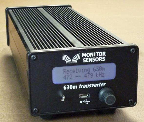
Now that beta testing is complete, production units are now ready for distribution from Monitor Sensors, a family environmental-sensor manufacturing company of which Roger is Governing Director.
The introduction of the VK4YB 630m Transverter presents another new option for those wishing to get on the band, or in the case of American amateurs, to get prepared for the band ... soon expected to be implemented in the U.S.
When I first started using the test unit provided, I was immediately impressed with how simple it was to set up and to get operational. It sits inconspicuously beside the main station's transceiver, taking up less space than the typical station speaker unit.
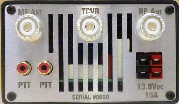
One usually associates 'transverter' operation with a rat's-nest of cabling or re-cabling to accommodate the new addition. The transverter arrived with all necessary cabling, even a nice Anderson power pole connector to connect the user-supplied 12V power source. A second pair of 12V contacts is also available for sharing with other station needs. One feature that I quickly appreciated was the dual RCA jack on the rear panel for controlling the transverter's PTT keying line. With my transceiver's PTT line already being used for another purpose, it was simply a matter of plugging-in (cable supplied) and sharing the line with the second jack ... no need for unplugging or using an external adapter to split the PTT line. Switching from 630m to normal HF operation is simply a matter of turning the transverter 'off' ... all HF operations are back to normal with antenna routing taken care of. There appears to be a lot of thoughtful engineering packed into this little box.
A look under the hood shows a well-planned and efficient use of space as seen in this pre-production prototype shown below. If Collins Radio were to manufacture a 630m transverter for the military, I can't imagine it being any better than this!
| prototype board under test |
"... we carefully match the FETs into three pairs. Each pair is matched to its opposite number but the pairs are chosen so 2 have low gain, 2 have mid gain and 2 have high gain. This improves the IPs and also the harmonics. With matched FETs we are getting the 2nd harmonic at typically -60dB. That's 10dB better than the stringent FCC requirement."
Roger's unit is running at 16 volts and produces 90W output, with his 630m WSPR signal being the one most often heard in North America from down under.
The transverter's multi-colored screen combines with a multi-function menu, allowing a visual on-screen display of numerous parameters such as RF output power, DC supply voltage and current draw, SWR, exciter drive power, heatsink temperature, graphic SWR display and various warning screens.
The transverter requires 3-5 watts of 160m drive from the station transceiver for full output power. Built-in safety circuits prevent overdrive from causing any damage. Similarly, transmitting into a high SWR or with no antenna connected is no cause for concern. Temperature sensors will trigger shutdown should the heatsink rise above 100 degrees C. Software also prevents out-of-band transmission.
This is a microprocessor controlled linear-transverter. This means that operating system software can be readily updated (via the supplied micro USB cable) as new features are implemented. It also means that any mode your transceiver is capable of operating on can be produced on 630m. At present, the most popular modes on the band are WSPR, CW and JT9 but I suspect this order may change once the band is opened up in the U.S.
A shortened eight-page Operator's Manual can be downloaded from the Monitor Sensors web site but units will ship with a more comprehensive 22-page manual. For more information regarding pricing and shipping, please contact Monitor Sensors here. For technical questions, please contact Roger here.
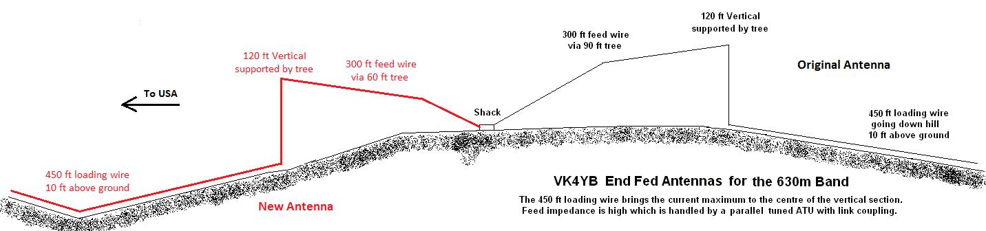
630m – The Path To VK
 |
| Roger, VK4YB |
I've been exchanging e-mails lately with Roger, VK4YB, in Queensland, Australia.
Roger is located about 30 miles from the ocean and has been the only VK signal that I have been able to hear on 630m WSPR mode. He seems to have the strongest signal out of Australia on 630m with his 90 watts and 120' tree supported wire vertical. John, VE7BDQ, has been heard twice down under with his modest station running at the allowable 5W EIRP limit, being reported in the fall of 2015 and again this spring. As well, John has heard Roger, the only signal from VK that either of us has copied.
I would like to be able to run some schedules with Roger in the fall, when transpacific paths should peak again. With that in mind, construction has begun on a new 630m transverter that will allow me to drive my present FET amplifier at full EIRP. Our schedules will utilize the JT9 weak signal mode, similar to JT65 but designed for the noisier LF and MF bands. It uses about 10% of the bandwidth that a JT65 signal requires, about 15Hz, and gains about 2db more sensitivity. A two-way QSO, under the best conditions, would take four minutes if all went well. A typical exchange of the required information, if initiated at my end, would look something like this:
VK4YB VE7SL
VE7SL VK4YB -20
R -18
RR 73
73 73 (not really needed but indicates RR received)
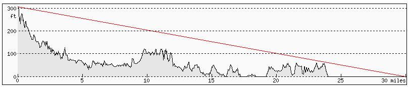
The path from my end is difficult as I am on the east side of Mayne Island and in Roger's direction, about one mile from a 600' hill directly in line with VK. Any RF heading Roger's way will need to leave here at a fairly high angle, which is likely the case anyway considering the low and short (in terms of wavelength) inverted-L antenna.
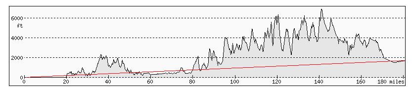
The path profile from here to the open Pacific Ocean is shown below, with my end being on the right edge, just behind those two hills. The rest of the obstructions are on Saltspring Island and then Vancouver Island, before hitting open water.
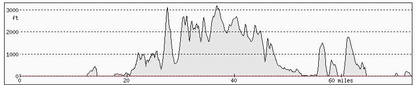 |
| VE7SL To VK4YB courtesy: Hey What's That Path Profiler |
 |
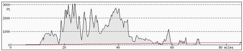
| W7IUV To VK4YB courtesy: Hey What's That Path Profiler |
 |
| To VK4YB courtesy: Hey What's That Path Profiler |
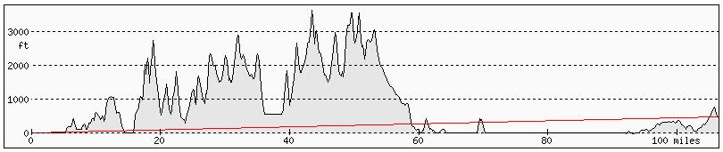
The path from John, VE7BDQ, already heard in VK, is also easier than from here. Not far from the water, John has a pretty clear shot across Georgia Strait, giving his signal lots of time to gain altitude and clear those pesky Vancouver Island peaks.
 |
| VE7BDQ To VK4YB courtesy: Hey What's That Path Profiler |
 |
| VE7CNF To VK4YB courtesy: Hey What's That Path Profiler |
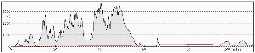 |
| VA7MM To VK4YB courtesy: Hey What's That Path Profiler |
 |
| VE7CA To VK4YB courtesy: Hey What's That Path Profiler |
 |
| VK4YB Path To Pacific courtesy: Hey What's That Path Profiler |
As the solar activity slowly abates (but not this week!), propagation on 630m will slowly get better and better ... hopefully along with increased levels of Canadians transmitting on the band, and lots of stations in the USA. It is hoped that our enthusiastic neighbours to the south aren't too far away from getting the band fairly soon. Better get those soldering irons warmed-up so you are all ready to go!


