Posts Tagged ‘vintage’
 Philco Tropic Model 3012
Last weekend I attended the Houston Vintage Radio Association holiday dinner & picked up a Philco Tropic Model 3012 during the fundraiser auction. I had let a few other radios go without placing a bid and was beginning to think I might go home empty handed when I saw the Philco “on the block”. A few seconds later I was the proud owner of this vintage receiver.
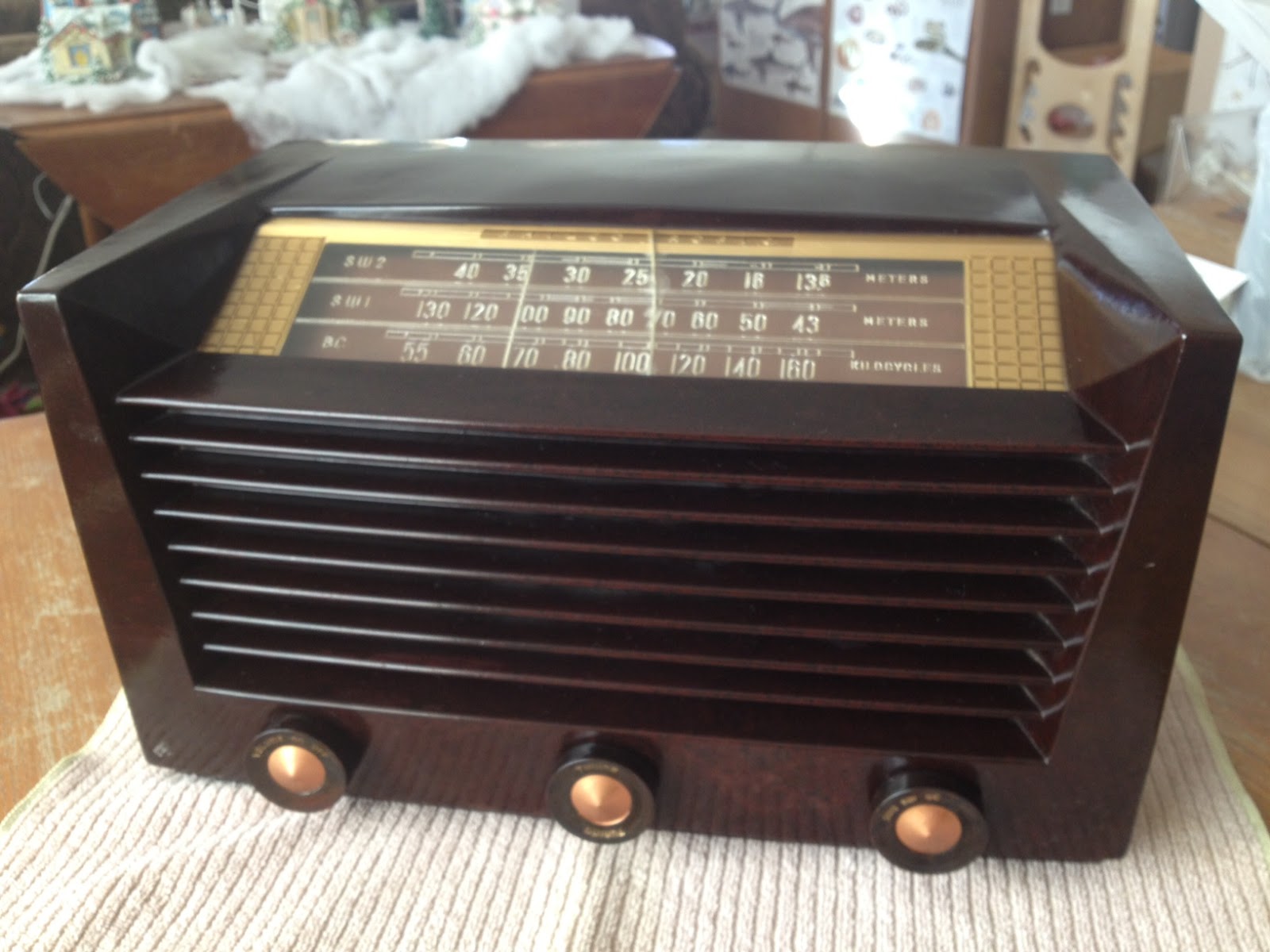 |
| Philco Tropic 3012 |
Information on this model seems a little scarce, however the style of case was introduced by Philco in 1951 and used in their line of AM/FM receivers for many years after that. This particular example is a transformer-less AC/DC set with a potentially live chassis and the unusual (to me) lineup of 14Q7, 7B7, 14B6, 35A5 & 35Y4 vacuum tubes.
What prompted me to bid on this particular radio was the inclusion of two shortwave bands in addition to the typical AM broadcast band. The dials are marked off in meters which also appealed to the ham radio side of my interests.
After attaching a short length of wire as an antenna I was able to pick up signals across the two SW1 & SW2 bands so I’ll be interested to see what it can receive with a long wire antenna at night.
After a gentle cleaning with dilute mild detergent to remove dirt I rubbed in some beeswax polish to restore the original gloss. Sadly the plastic dial is cracked in the middle but I can look past that given its a little more unusual than the typical All American Five receiver.
Being over fifty years old I wonder what this radio has been used to listen to and what stories it could tell. Perhaps it gave some youngster his or her first taste of ham radio, listening to shortwave stations and AM QSOs until they received the final demand to, “Switch that radio off and GO TO BED!”
The Johnson 275W Matchbox Antenna Tuner
I had purchased a Johnson Matchbox from an estate a while back & decided that while I was home with the flu I would open it up and check on its condition.
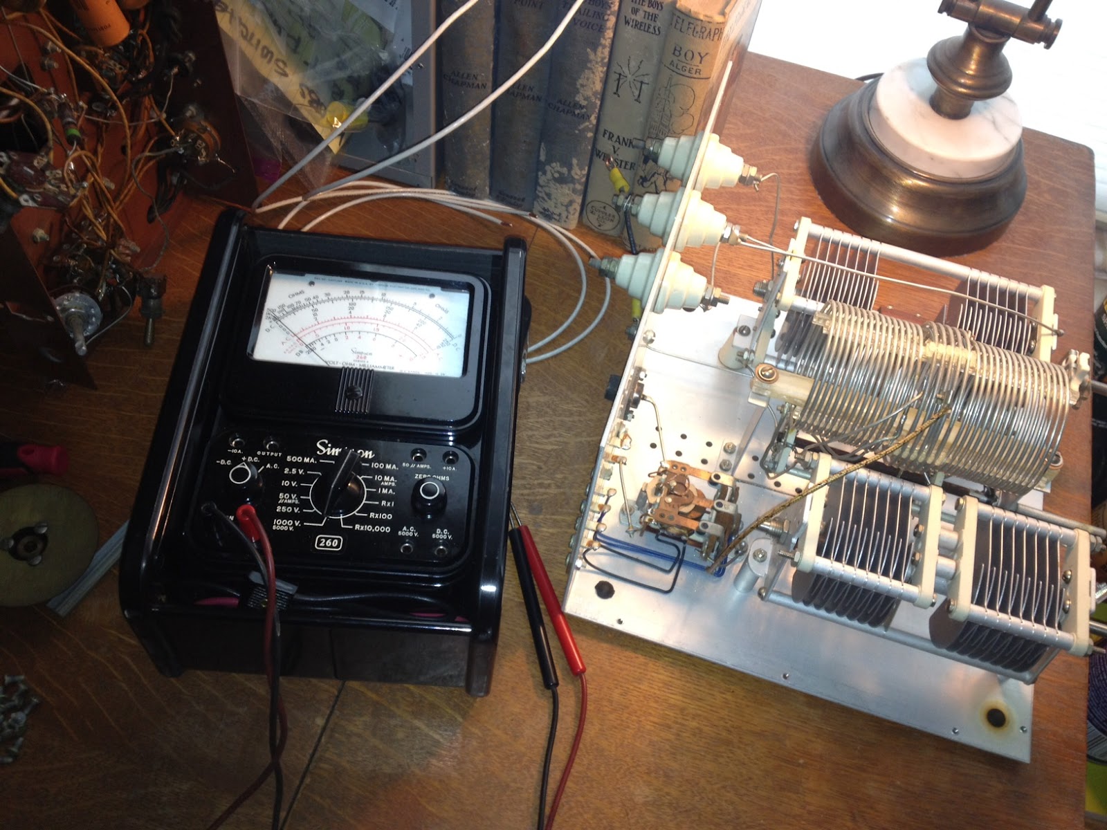 The Johnson Matchbox is found most commonly in two versions, the smaller “275W” unit and the larger Kilowatt Matchbox. Why did I use quotation marks around 275W? Well, these units were manufactured back in the good old days when men were men and transmitting voice meant using AM, not single side band. The conservative rating of 275W of AM translates into roughly 800W of peak SSB (Not really but close enough so you get the idea)
Unlike many who own a Matchbox I was hoping to keep it 100% original and that it would contain all its original components, including the antenna change-over relay and wiring for the high-impedance receiver antenna connections. I plan to use this Johnson Matchbox with a Heathkit AT-1 transmitter and Hallicrafters SX-25 receiver so the inclusion of an antenna change over relay and 300 Ohm receiver connections will make life MUCH easier. Something I didn’t realize until I had the unit apart (There are a LOT of screws holding this thing together) is that there is also a receiver control contact on the relay to break HT and mute the receiver during transmit which will work with my SX-25.
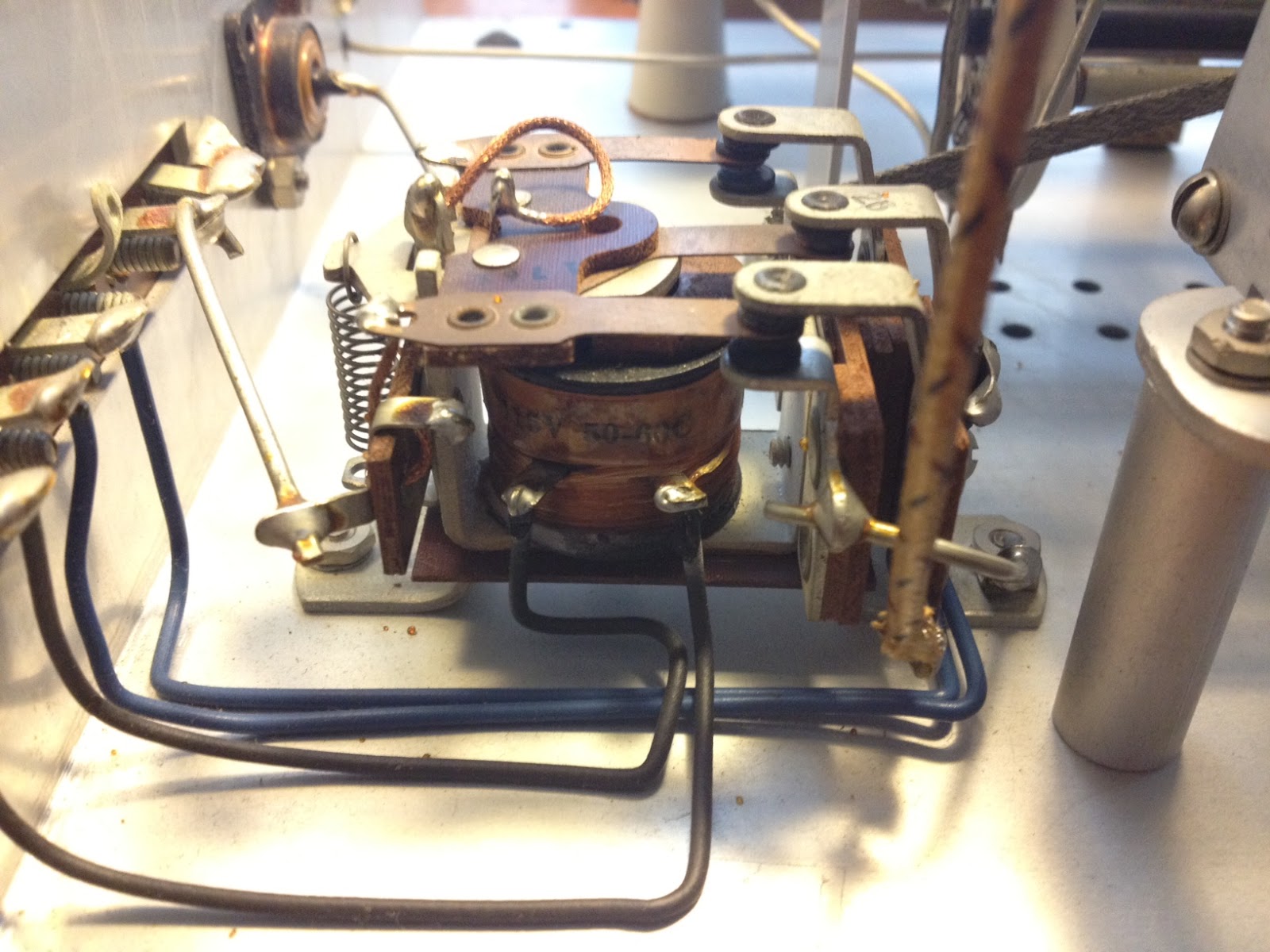 An initial inspection showed that the only modification was a small piece of plastic wedged into the relay contacts that held the relay in the transmit position. It was easily removed and the relay coil and contacts tested for continuity. The contacts seem a bit dirty which, from the little I have read online, seems to be a common problem.
Once the relay contacts and band-switch are cleaned I will button the unit back up and connect it to the loop antenna I have recently run around the eaves of the house. The loop has been a huge improvement to the long-wire and magnetic antennas I have run in the past, at least as far as reception goes … but that is a topic for another post.
The further adventures of the Heathkit AT-1
Work has been conspiring to eliminate my spare time but I was able to spend a few hours over the Easter holiday to clean up the shack and make space to put the Heathkit AT-1 on the desk again. I have been able to spend a little time going over parts that need to be replaced and making a list.
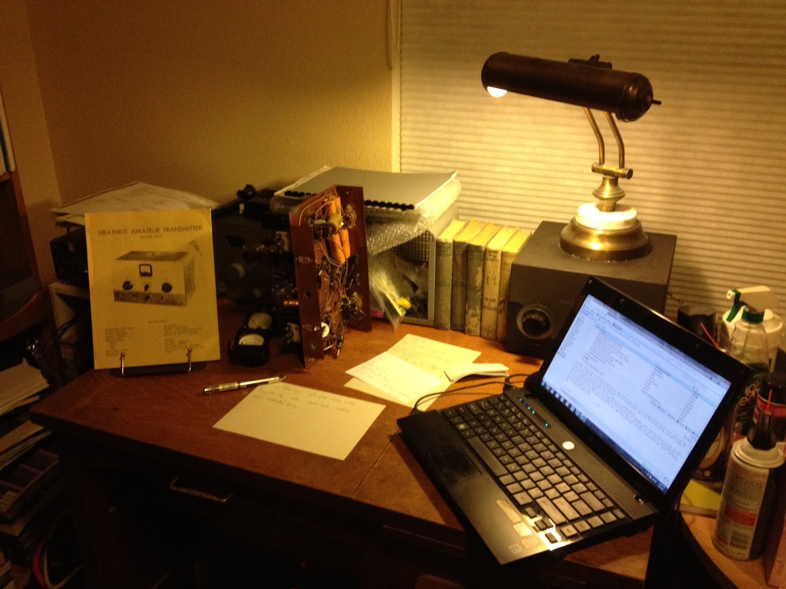 |
| The Heathkit AT-1 chassis with case and VFO-1 behind. |
There doesn’t seem to be any show stoppers although the wafer of the meter switch has broken in two and will need to be repaired. If I’m not able to repair it then thankfully it is fairly simple and replacement rotary switch can be substituted.
This isn’t going to be a museum quality restoration but the changes that were made to this transmitter in the past were sensible and if left in place are representative of period modifications. The original meter for example was not the highest quality and a Western or Simpson replacement would be an improvement. The original slide switches have been replaced with period snap-toggle switches which are also an improvement over the original.
The Heathkit VFO-1 however has been modified for grid-block keying which is a significant departure from the original and I plan to revert it back to cathode keying. Although a technical improvement it is not in keeping with the original design and needs to be undone. Everyone will have their own opinion but I think if I wanted modern circuits I’d get a more modern rig, so the VFO-1 will be returned to stock.
Hopefully I can carve out a bit of time here and there to work on this and slowly return it to working condition.
Making a Type C Triode – Amazing Glasswork!
Ron Soyland is at it again and creating a Type C Triode vacuum tube. For a look at other creations click on Making a Spherical Audion Tube by Ron Soyland
A general purpose triode originally made for use by the Royal Air Force (Great Britain) in 1918 and designed by Captain H. Round of the British Marconi Co. around 1913. It is a triode that was meant for high gain high frequency use and has a 3 volt directly heated cathode.
Heathkit’s first amateur transmitter – Heathkit AT-1
The Heathkit AT-1 represents the commercial embodiment of the simple Master Oscillator Power Amplifier (MOPA) transmitter using a crystal controlled 6AG7 oscillator plus a 6L6 final output tube.
Although it was possible to design and build a simpler transmitter, the goals of output power and stability could become mutually exclusive when trying to operate with only one tube. For a novice class license holder of 1951 the Heathkit AT-1 represented a solid performing rig that would be relatively easy to construct and operate.
The Novice remained the primary entry license until the Morse code requirement was eliminated for Technician licenses in 1990. On HF it permitted code transmissions only, with a maximum power of 75 watts, (input to the transmitter’s final amplifier stage) on limited segments of the 80, 40 and 15 meter bands.
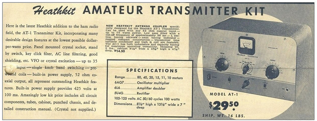 |
| For $29.50 and the loan of a few tools you could get some use out of that new novice license |
The earlier MOPA circuit from the ARRL handbook of 1941 below shows a layout remarkably similar to the circuit of the AT-1 although it is designed for plug in coils rather than the band-switching arrangement of the later Heathkit transmitter.
| MOPA transmitter using a 6L6 and an 807 as the power amplifier (ARRL Handbook 1941) |
For a little added complexity MOPA transmitters generally offered better stability of frequency and keying waveform than single tube crystal controlled or self exited rigs. The straight forward design of the AT-1 should have looked familiar to novice class hams after studying the ARRL handbook or other radio publications.
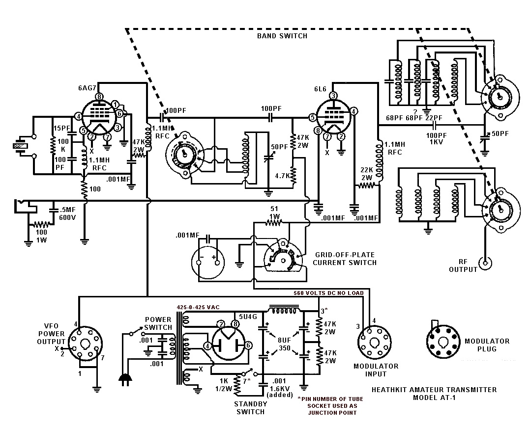 |
| Heathkit AT-1 Circuit diagram showing band-switching arrangement and link coupled output |
Once the novice had upgraded his license the AT-1 could be expanded by the addition of the Heathkit VF-1 variable frequency oscillator to allow transmission on any frequency within the allowed band.
 |
| The Heathkit VF-1 Variable Frequency Oscillator |
The VF-1 covered 160-80-40-20-15-11-10 meters and used an OA2 voltage regulator tube to provide a stable voltage for the oscillator. Ceramic coil forms, solid construction and high quality components were used to help increase stability.
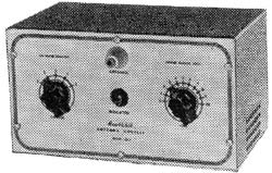 |
| The Heathkit AC-1 Antenna Coupler. Designed to attach to a single wire by the insulated post on the front panel. |
 |
| Heathkit AC-1 Antenna Coupler circuit diagram |
Although Heathkit did not produce a AM modulator for the AC-1 there is provision for modulator connection on the rear panel. The earlier ARRL manuals have several suitable circuits for modulators that would work with the AC-1. Most functioned by driving a modulation transformer with the output from an audio power amplifier. The secondary of the modulation transformer would be carrying the DC plate supply for the power amplifier tube plus or minus the instantaneous voltage of the audio waveform. By changing the plate voltage to the final amplifier tube the radio frequency output would be controlled by the amplified audio frequency resulting in amplitude modulation.
Pop’s Shed and the Kingsley Radio AR7
After my grandfather passed away I spent a lot of time recalling the good times I had spent scrounging around his CB shack and hanging out with Pop “down the shed”. If you’ve spent time around old motorbikes, retired lawn mower engines, vacuum tube electronics and inches of dust you know what the shed smelt like and probably have a pretty good idea what it looked like as well. I used to be able to send Mum into fits by embedding a combination of oil, grease, dust and grinding compound into the knees and sleeves of my good clothes after spending the day “over south” (South Geelong)
Even now I can still walk into any old auto mechanics and the smell brings back dozens of memories as clear as day … but one memory in particular had been bugging me for a while now. On several occasions I had used a magnificent rack mounted shortwave receiver that had been hooked to a long-wire antenna between the shed and the house. It had several plug in coils housed in bright metal boxes, one for each band as well as a unique tuning dial that had windows around the circumference with numbers that updated as the dial was turned.
 |
| National HRO right? … Nope, its an Australian clone! |
For the longest time I was thinking what you are probably thinking now, I had been using a National HRO receiver right? Well, you’d be wrong … just as I had been for years! When I eventually asked my uncle about the receiver (I waited a long time as I feared it had been thrown out & honestly didn’t want to know if it had) he said, “The AR7?” … “Yes, its here in the garage covered in dust”. He went on to say that I could have the receiver if I could figure out some way to ship it … not a slight problem given the receiver, power supply and speaker are over 120 lbs!
Knowing now that I had been using a completely different receiver I set to work and found out what I could about this National HRO clone …
From : http://www.vk2bv.org/
The AR7 was produced during WW2 by Kingsley Radio of Melbourne for the R.A.A.F. These receivers were used in ground stations for long range communication over fixed circuits as well as for receiving signals from aircraft.
The AR7 was based largely on the National (USA) HRO model, a fact that did not go unnoticed by National. This was the subject of litigation during the war years. Over 3000 of these receivers were produced and for their time, produced excellent performance.
These sets were very popular with radio amateurs after the war and unfortunately subject to many modifications. The Wireless Institute of Australia station, VK2WI at Dural New South Wales was equipped with modifed AR7’s for many years. I seem to remember that very local operators could block the receivers completely, resulting in hurried phone calls!
An unmodified AR7 is a rare beast. The Department of Civil Aviation used these sets for many years in a highly modified form, requiring a new front panel. Refinements included squelch and crystal locked coil boxes.
From : http://www.shlrc.mq.edu.au/~robinson/museum/AR7/
The AR7 is a communications receiver covering LF and HF bands. It was made in Australia during 1940 and bears an extremely close resemblance to the National HRO receiver. The receiver has a tuning range from 138 kcs to 25 mcs, with a gap of 45 kcs either side of the 455 kcs IF amplifier. The internal design is a single conversion superheterodyne receiver with 2 RF stages, 2 IF stages, a BFO and an “S” meter amplifier. The sensitivity is quoted as 1 microvolt. The front panel is stainless steel and it is a very distinctive looking receiver.
It is a good performer, sensitive, has a nice feel, is easy to tune, but hard to find the correct frequency, by reading the frequency from the dial number and coil box graph. It really needs a crystal calibrator. I use it for the weekly W.I.A. (Wireless Institute of Australia) broadcast, so it gets turned on once a week, and is so stable, than I don’t have to retune. It is very clear for AM but a bit fiddly for SSB.
The controls are: RF gain, BFO note, AVC/BFO switch, Adjust “S” meter, Tone, Tuning, Noise limiter, Selectivity, Crystal IN/OUT switch, Crystal Phasing, Audio gain. The Audio gain control has an OFF position which removes the HT so that the coil boxes can be changed.

It has two 6U7G RF stages, a 6K8G mixer, two 6U7G IF stages at 455 kcs, a 6G8G detector/AVC/audio preamplifier, and a 6V6G audio output amplifier. It has a 6C8G twin triode as a BFO and “S” meter amplifier. It also has a crystal filter. The IF alignment should be done very carefully, as any misalignment will reduce the effectiveness of the filter. It is best done with a sweep generator. The 6 volt valve heaters are connected in series, for 12 volt operation.
The external power supply and speaker, are usually mounted in a short 19″ rack, the AR7 at the bottom, the speaker in the middle, and the power supply at the top. The complete unit weighs about 118 pounds. The power supply was switchable between 12v and 240v.
The receiver was used as a ground monitoring receiver for aircraft. It was extremely stable. The model shown has an R.A.A.F. nameplate, and serial number 1786. The manual I have is a D.C.A. (Department of Civil Aviation) version and is a 1947 issue.
It has 5 plug in coil boxes. The coil boxes are: band A 140-405 kcs, band B 490-1430 kcs, band C 1.420-4.3 mcs, band D 4.25-12.5 mcs, band E 12.5-25 mcs. The Army version had an extra coil box covering 50-150 kcs. The large dial is a 20:1 reduction drive and has graduations from 0 to 500. It acts like a flywheel when tuning across the band, and has an effective scale length of 12 feet. The dial shaft goes into a right angle reduction gearbox and has 2 output shafts that drive 2 dual gang capacitors. The graph on the front of each coil box is used to covert the dial reading to frequency.


