Posts Tagged ‘project’
 The list of projects is huge!
I have been having serious radio withdrawal – I am really itching to get on the air and operate! Unfortunately, life is happening and I have had zero time to operate.
When this happens I usually watch a lot of videos and read blogs. This then leads a big list of “I wanna do that” type projects.
So I thought I would list the top 3 or 4 here and set a goal of getting them done by Christmas:
1. Get a long wire inverted L 9:1 UNUN antenna installed at the house. I have the UNUN built and I have the small gauge “stealthy” wire from the Wire Man – just need to get it up in the trees!
2. Rockmite 40 – I have had this kit along with the Mitybox for several years – just need to get it built.
3. DIY Powerpole Distribution Block – There are some great plans for this here: http://www.qsl.net/wd4bis/connect.htm
4. Magnetic loop antenna with automatic controller. I have the board, just need some components to get the board built up and working – I really want to get this going early this fall!
The list is much longer – but this is the top four I want to get done right now.
What is on your project list?
The list of projects is huge!
I have been having serious radio withdrawal – I am really itching to get on the air and operate! Unfortunately, life is happening and I have had zero time to operate.
When this happens I usually watch a lot of videos and read blogs. This then leads a big list of “I wanna do that” type projects.
So I thought I would list the top 3 or 4 here and set a goal of getting them done by Christmas:
1. Get a long wire inverted L 9:1 UNUN antenna installed at the house. I have the UNUN built and I have the small gauge “stealthy” wire from the Wire Man – just need to get it up in the trees!
2. Rockmite 40 – I have had this kit along with the Mitybox for several years – just need to get it built.
3. DIY Powerpole Distribution Block – There are some great plans for this here: http://www.qsl.net/wd4bis/connect.htm
4. Magnetic loop antenna with automatic controller. I have the board, just need some components to get the board built up and working – I really want to get this going early this fall!
The list is much longer – but this is the top four I want to get done right now.
What is on your project list?
What next for the autumn?
My thoughts are starting to turn towards amateur radio this autumn.
Unlike in previous years, I cannot imagine being fully fit by then. So, I shall be on the lookout for some new challenges that don’t involve driving, don’t involve building and probably don’t require much, if any, antenna work. Also, it would be helpful if actual talking is kept to a minimum as I find talking very tiring.
I suspect JT65 and JT9-1 will be on the list as I can use (some of) these modes on 630m, 40m, 20m, 10m, 6m, 2m and 70cm with existing antennas. I may ask for some help to improve my earth electrode antenna for 630m. With luck I may be able to drive again later this year. This means I might be able to restart some field work again.
If you have any suggestions let me know.
Maybe I should try for QRP DXCC on JT65/JT9-1? No talking, use existing antennas and rigs, and a new challenge.
The unfortunate & epic saga of the perfect military radio
 |
| The long awaited but ultimately unwanted GMR radio |
As my day job starts to include more long term projects & project management I was particularly intrigued by an article in arstechnica.com. The article is, “How to blow $6 billion on a tech project“, although the title may be more inflammatory than technically accurate.
The article covers the 15 year development of an advanced & unified military radio communications system that suffered from multiple issues including scope-creep & a rapidly changing underlying technology.
If you are involved with a group that is working to develop a product or service you’ll really get something from this article. If you interested in radio systems, military or otherwise, you’ll find this interesting as well.
Its hard to image the frustration people suffer when contributing to a project that is mismanaged unless you have been there yourself. I hate to think of the wasted effort that resulted when people found out How to blow $6 billion on a tech project
The further adventures of the Heathkit AT-1
Work has been conspiring to eliminate my spare time but I was able to spend a few hours over the Easter holiday to clean up the shack and make space to put the Heathkit AT-1 on the desk again. I have been able to spend a little time going over parts that need to be replaced and making a list.
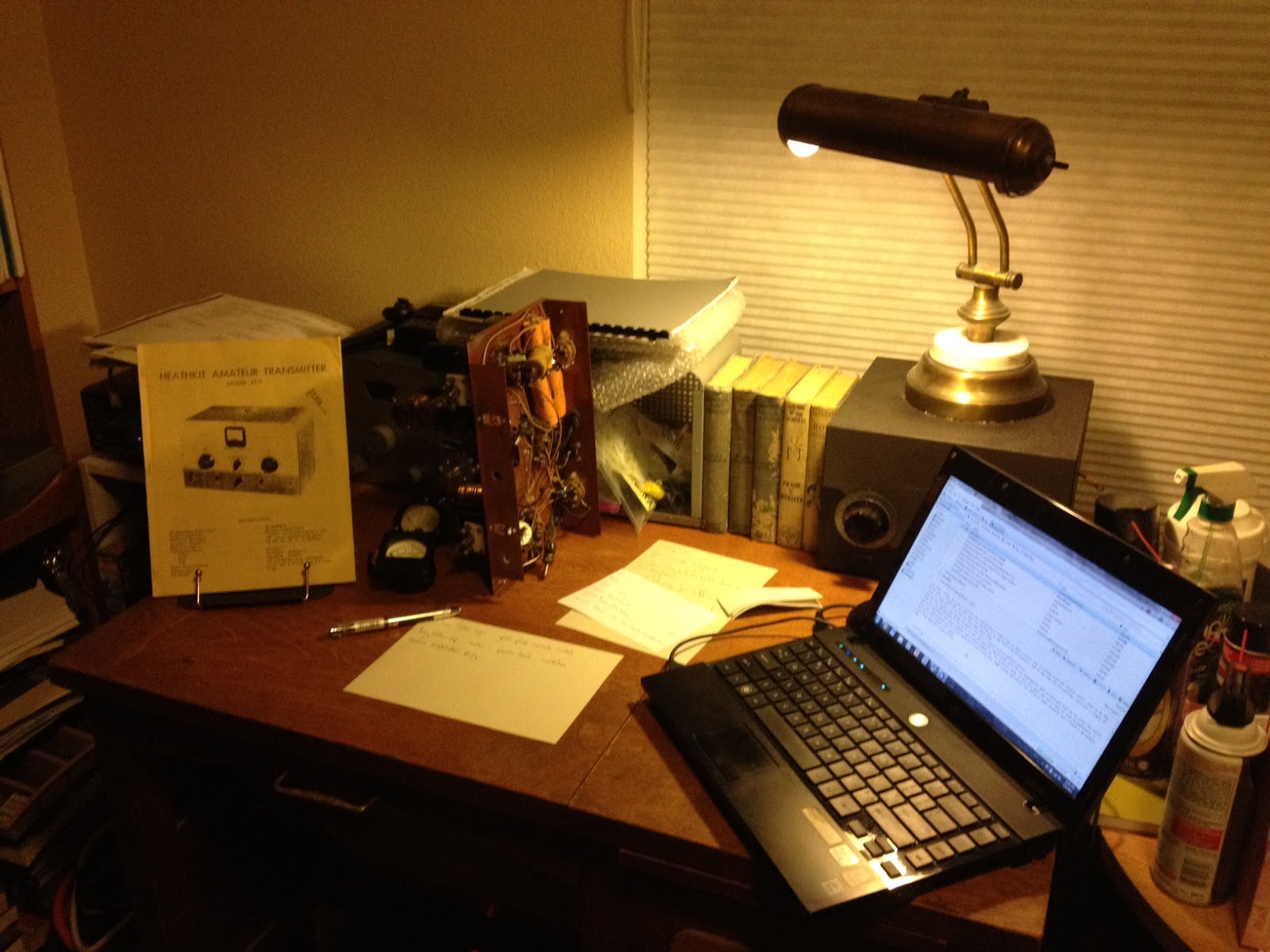 |
| The Heathkit AT-1 chassis with case and VFO-1 behind. |
There doesn’t seem to be any show stoppers although the wafer of the meter switch has broken in two and will need to be repaired. If I’m not able to repair it then thankfully it is fairly simple and replacement rotary switch can be substituted.
This isn’t going to be a museum quality restoration but the changes that were made to this transmitter in the past were sensible and if left in place are representative of period modifications. The original meter for example was not the highest quality and a Western or Simpson replacement would be an improvement. The original slide switches have been replaced with period snap-toggle switches which are also an improvement over the original.
The Heathkit VFO-1 however has been modified for grid-block keying which is a significant departure from the original and I plan to revert it back to cathode keying. Although a technical improvement it is not in keeping with the original design and needs to be undone. Everyone will have their own opinion but I think if I wanted modern circuits I’d get a more modern rig, so the VFO-1 will be returned to stock.
Hopefully I can carve out a bit of time here and there to work on this and slowly return it to working condition.
DIY Magnetic Loop Antenna – Part 3
Well, I finally have had time to sit down and put together part three of the DIY Magnetic Loop Antenna, sorry it has taken so long!
This post will cover building and coupling the loop to your transceiver. After reading through posts one and two you should have a good idea of the parts you’ll use and the physical dimensions of the main loop.
DIY Magnetic Loop Antenna – Part 1
DIY Magnetic Loop Antenna – Part 2
Most magnetic loops have the capacitor at the top of the main loop and the gamma match or matching loop at the bottom, this arrangement avoids running the feed-line through the center of the antenna.
You can assemble the main loop from continuous copper tube or from eight straight sections and 45 degree joiners. Make sure you have a blow torch or propane torch to solder the joints as you’ll need more heat than a soldering iron can supply. Whichever way you decide to build the main loop make sure that all joints are soldered or clamped as securely as possible, you want the lowest resistance possible to avoid your output power turning into heat. Other materials can be used for the main loop such as aluminium or low loss coax but copper pipe is easy to work, has low resistivity and available from just about every hardware store.
To construct the frame of the antenna you can use PVC pipe. It is a cheap and relatively sturdy building material and is available in a range of thicknesses, just about any hardware store will stock a wide selection of fittings. It insulates well and can be glued once you are sure your project is in its final form.
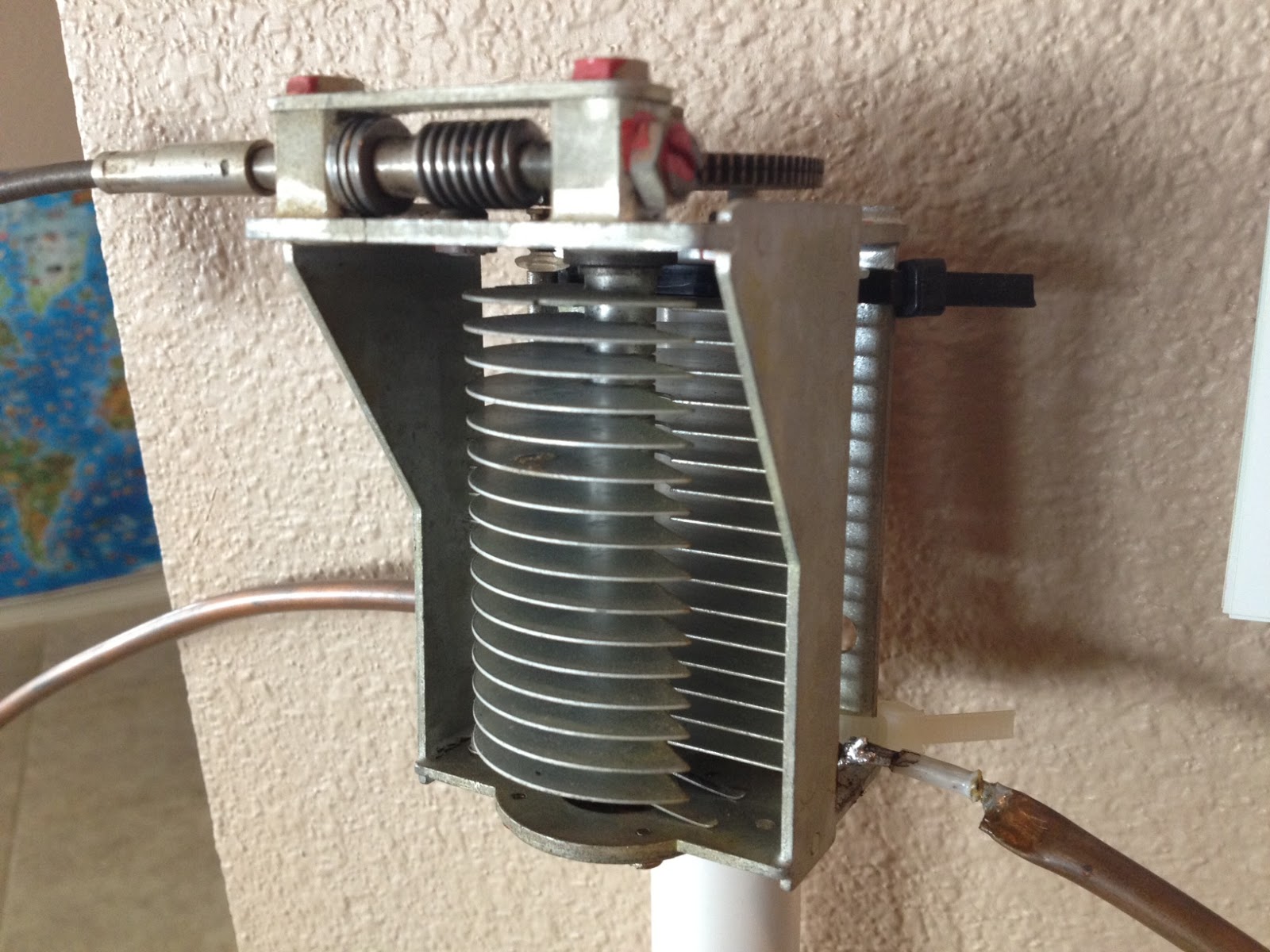
Once the main loop is constructed you’ll need to connect your capacitor to the two ends of the pipe at the top of the loop. Depending on the capacitor you may want to solder tags to the ends of the loop so they will be easier to attach. Copper pipe is a great conductor of heat and takes a lot to heat up and solder while it is not advisable to apply the same amount of heat to your capacitor.
It is also a good idea to attach the capacitor to a solid support so that the connections are not under strain.
The main loop and the capacitor forms the resonant circuit of the magnetic loop antenna.

To couple the main loop to your transceiver and match the expected 50 Ohms impedance you can use one of two methods. Probably the easiest is to use is a loop of insulated wire 1/5 the circumference of the main loop. The smaller loop is placed at the bottom of the main loop and can be shifted around to provide the best match. If you have an antenna analyzer you’ll be able to set it to the desired frequency, tune the variable capacitor for resonance and then move the small matching loop around till you have achieved close to 1:1 SWR. If you don’t have an antenna analyzer you can tune the capacitor for the greatest received noise and then on low power tweak the capacitor and move the coupling loop around for best SWR. Do NOT touch the loop while it is transmitting, use a wood or plastic rod to make adjustments as there are high voltages and intense RF fields near the loop.
An alternative to the coupling loop is the gamma match. The shield of the coax feed cable is connected to the base of the main loop while the inner conductor is connected to a point approximately 1/5 of the circumference around the loop. Its a good idea to use stiff wire (large gauge) for the gamma match as it can be critical of the position and orientation and once you have it in the right position you won’t want to move it again.
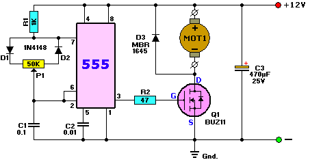
It would be preferable to have the ability to remotely tune the loop. A motor with a reduction gear could be used to move the variable capacitor but because the point of resonance is very narrow there should be a way of slowing the motor down. A simple control circuit using variable pulse width modulation could be used to slow the motor down while still retaining enough torque to move the capacitor. Whatever method is used to move the capacitor it should be well insulated from the other components of the antenna. Several thousand volts are generated on the MLA and care should be taken to ensure they don’t find their way onto control leads and back into the shack. Control leads should also be wrapped around toriod inductors as they leave the near field of the antenna to reduce the possibility of RF travelling along them.
With a SWR bridge and microcontroller you could build a fully automatic tuner that swept through the range of the tuning capacitor when the SWR rose above a defined limit indicating that the transmit frequency had changed.
With a little creativity and knowledge you could have an impressive MLA the equal of multi-thousand dollar military style units.
Hopefully this has given you some ideas for constructing your own loop antenna. Regardless of if you go top-of-the-line and buy a vacuum variable or build for economy and QRP you’ll have a compact, useful and unique antenna.
Now I understand – Phase Locked Loops
Every now and then I come across great books or videos that explain a concept in such a way that it becomes immediately obvious what is going on. I’m a great believer in learning by demonstration or even better, learning by doing.
I came across another explanatory video recently that I thought was too good to keep to myself. It covers a topic that was a complete mystery to me: Phase Locked Loops. We utilize them in almost every modern transmitter and receiver yet most people I have talked to view them as a black box that, fortunately, does its job well and usually without interruption.
The video below does a good job on opening the black box and showing just what makes phase locked loops … well, lock.


