Posts Tagged ‘modification’
 Finally got my Ultrafire WF-501B as I wanted it

As I wrote in my blog post a few days ago, I got the intensity down for night vision for my red flashlight. But I wasn’t quite happy with the level and wanted to reduce it even more. To do that I had to unsolder 6 of the 8 AMC7135 350 mA constant current ICs on the PCB of the AMC7135*8 2800mA 4-Group 5-Mode Circuit Board.

These constant current chips are all run in parallel with the VDD input for control. The 8-pin Atmel ATtiny13A chip controls all VDD inputs in parallel from its pin 6. When the VDD pin is low there will be now light. I haven’t measured this, but I am assuming that this pin is pulsed in order to reduce current down from the maximum.
My measurements for the High, Medium, and Low settings are:
- 8 chips: 2,8 A, 0.83 A, 0.14 A
- 4 chips: 1,4A, 0.45 A, 0.08 A
- 2 chips: 700 mA, 225 mA, 42 mA
This scales as expected with the number of 350 mA chips and the 100%, 30%, and 5% settings of the controller. Now only Q1 and Q3 remain, and Q2, Q4-8 have been desoldered.

One could have obtained en even more battery-friendly version if somehow the original controller could have been modified. The step-down circuit is quite standard with an inductor, a Shottky diode (SS14), and a controller chip of unknown origin. But it seems to me that if R23 of value R250 (0.25 ohm) was increased, output current would probably go down.
As it is I am much more happy with the intensity of the settings I have now. It will be a good companion night light which will preserve night vision well when used with a telescope.
Dimming my Ultrafire WF-501B
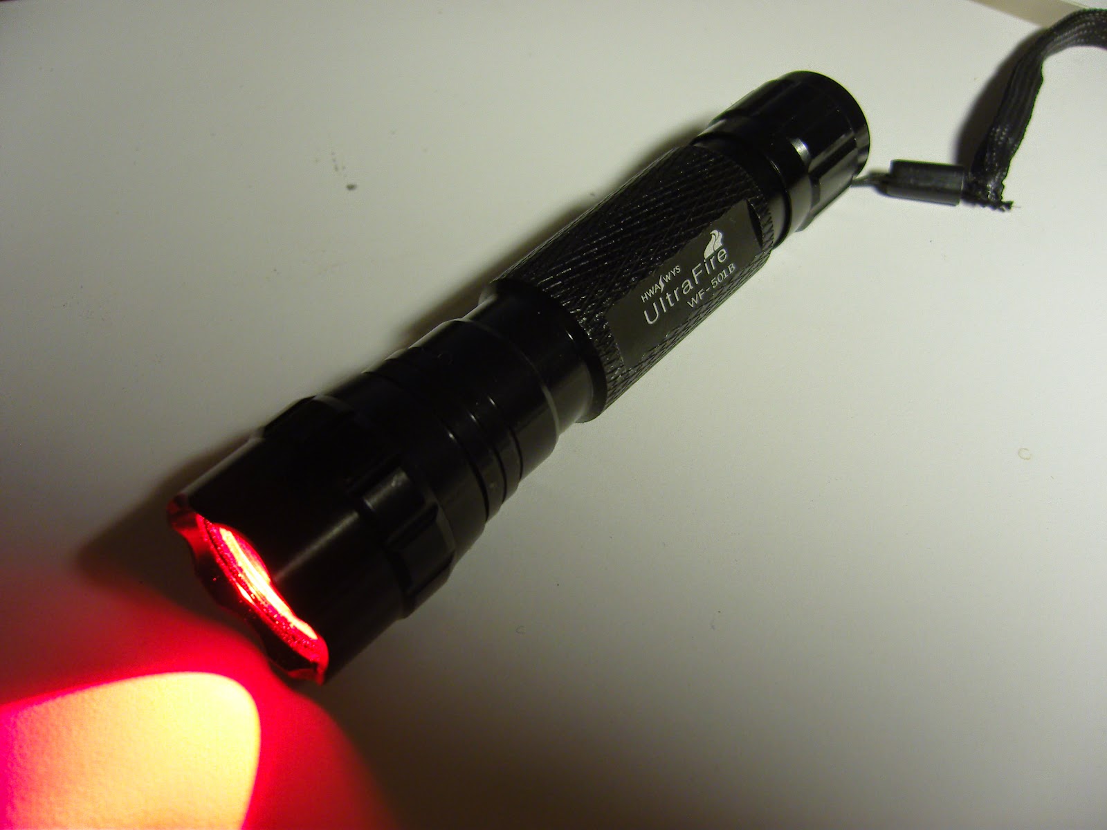
I got this red LED flashlight as a Christmas present. But unfortunately the intensity was way too high for what I intended to use it for. A soft red light preserves your night vision, and is ideal for use with a telescope in the dark as was my intention. But if the intensity was as high as before the modification, night vision would suffer.
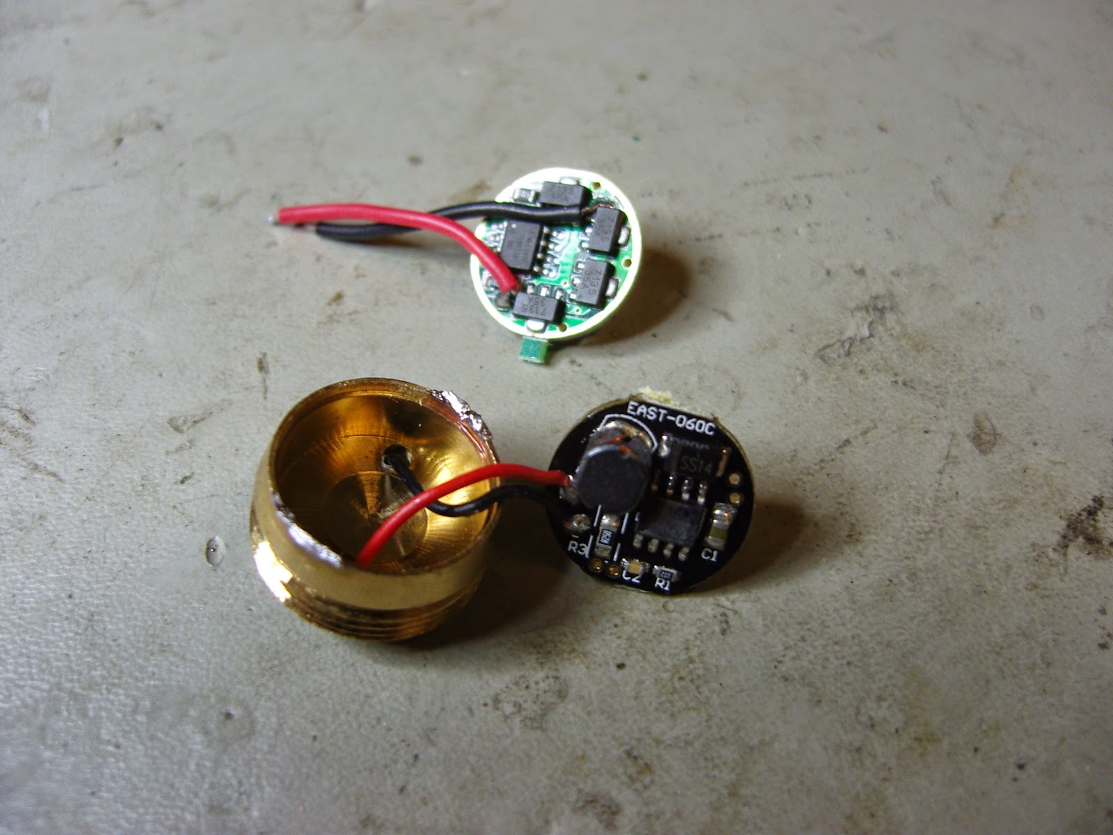
I then found this YouTube video describing how the controller circuit board could be replaced by one with more functions. As recommended I therefore ordered an AMC7135*8 2800mA 4-Group 5-Mode Circuit Board with 8 AMC7135 current regulators in parallel. The image shows the the original circuit board as connected before the modification in the front in the image and the new one behind it.
 The new board gave me the choice of one of 4-groups:
- 3-mode: Lo (5%) – Hi (100%) – Strobe
- 3-mode: Lo (5%) – Mid (30%) – Hi (100%)
- 2-mode: Lo (10%) – Hi (100%)
- 5-mode: Lo (5%) – Mid (30%) – Hi (100%) – Strobe – SOS


