Posts Tagged ‘lightwave’
 ET Call Home

Late last week I received an interesting e-mail from Thomas Pell in Winter Haven, Florida.
It seems that Tom has been doing some building after reading my series of blogs about my lightwave adventures and has started his own adventure. As he told me initially:
"... I'm retired with too much time on my hands, and I'm tired of the big gritty hobby projects ... after reading about Harvard U's optical SETI project, which looks for extraterrestrial laser signals with a 48 inch, then 72 inch mirror. I thought it would be fun to build a setup like theirs, but at audio frequencies instead of the RF laser signals ... my purpose was to get light signals from other amateur laser dx experimenters or even ET ... better than watching my wife's TV shows. Also a giant telescope that costs almost nothing is fun too."
Tom built up the PIN diode detector shown in my notes, which was a slight variation of the one developed by Roger, G3XBM (see his great lightwave notes here) and based on an earlier plan by K3PGP.
Along with the receiver, Tom built a substantial optical antenna ... a 48" Mylar-based parabolic mirror!
"... it is a wood structure ... round piece of 1/2 inch plywood, 48" in diameter ... around the perimeter a 4" wide strip of 1/8" plywood is wrapped and glued with epoxy putty. On the upper end of 1/8 ply is another circular plywood flange inside. This flange is to glue mylar sheet. The mylar is then tensioned with tape on the side. It is something like a round guitar in appearance... a box ... you suck the air out ... I use a shop vacuum with 1/4 in rubber tube taped to vacuum hose ... hose barb epoxied to hole inside of mirror ... not ideal but if you seal it up well with epoxy, it works..."
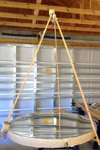 |
| courtesy: Thomas Pell |
It seems that there is now an active movement amongst some SETI enthusiasts to search for optical beacons rather than radio beacons. When you think about it, it would seem to make just as much sense, if not more, to beacon with a modulated optical signal than with a radio signal ... and the optical signal might be far easier to detect. Some of the papers suggest that an optimum frequency would be in the near IR or deep red part of the spectrum, right where most optical amateur two-way work is presently being done.
During his first few tests of the new mirror, Thomas stumbled upon one signal (the only one) which came from just one single point in the sky ... almost directly overhead in Orion.
"At 9:30 pm 3/5/2015, using the amplifier circuit you use in your optical communication receiver connected to a 48 inch parabolic mirror, I received an apparently modulated optical signal originating in center of Orion constellation. Signal was audio frequency low to high pitch and lasted for more than an hour. I located the signal by moving the mirror back and forth across the sky for nearly an hour until I found a "blip", then focused the mirror exactly on the spot to listen to it, incredible experience."
"Received signal again last night from same location. I am becoming convinced it is information of some kind.Very irregular rapidly pulsed. This was only a test of amplifier ... I never expected this result, was totally unprepared. Meanwhile time is passing and I can't seem to contact anyone to have it confirmed before it disappears from the sky. It seems, no one has a setup like this ... this signal is either very important or it's nothing ... I think. Will let you know about outcome."
At this point, Tom is just trying to figure out what type of signal he has been hearing and will be attempting to get a better recording of it over the next few nights. I have heard his initial recording, just done with an I-pad held close to the amplifier's speaker output and it does sound suspiciously like a data train of clicking pulses. Hopefully Tom will solve the mystery soon!
Measuring The New Lenses

Yesterday I had the chance to have a closer look at the two lenses recently purchased for a new portable lightwave receiver. The initial testing procedure of the page-size fresnel (actual size is 200mm x 270mm) proved incorrect and required more space than the bench top could provide. Eventually the focal length was measured as ~ 368mm +/- for an f/d, or F number, of 1.36 ... a convenient value and much better than the 'other' common fresnel page reader focal length of ~ 600mm. This jibed nicely with the recommendations given in Clint's (KA7OEI) website optical information:
"For practical reasons, it is recommended that an optical system using Fresnel lenses be designed using lenses that have an F-number in the range of 0.5 to 1.5 - that is, around 1. Remember: The "F-number" is the focal length divided by the diameter of the lens, so for an F-number of unity or one, the diameter of the lens would be the same as its focal length."
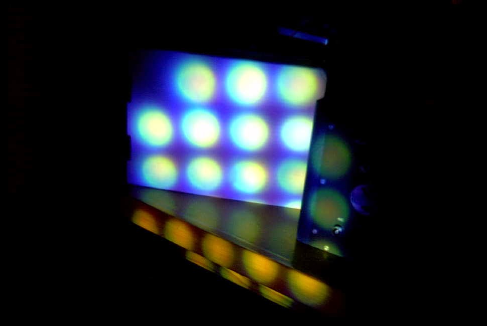
The lens was able to bring a small LED flashlight (consisting of an array of 21 white LEDs) into surprisingly sharp focus although the shot below does not reflect that due to my camera's poor focus in the darkened room.
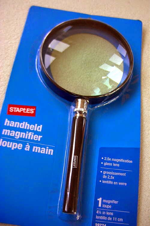
The glass 4.5" magnifying lens proved to have a focal point of 203mm for an F number of 1.8. This lense produced an even sharper image of the same light source and may be the best candidate for the portable receiver although the larger aperture of the fresnel might not be worth counting out at this point.
The fresnel may work well for a transmitter and will likely require a small (inexpensive) secondary focusing lens between the LED and the fresnel, in order to have the LED efficiently illuminate the fresnel. The secondary should effectively gather and focus as much of the emitted LED light to just within the boundaries of the fresnel without any wasted light energy being lost to spill-over at the edges.
It would be great to have a permanent lightwave 'beacon' that one could test various receiver lenses and combinations but at present there is very little activity here in VE7 land ... although that is changing, with the interest of another local, VE7IGH (Greg) near Vancouver and right across Georgia Strait from my location. Grant has already built a receiver and will soon start on transmitter construction ... way to go Greg!
’29 MOPA / NLOS Lightwave Progress
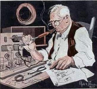 |
| Courtesy: http://www.arrl.org/ |
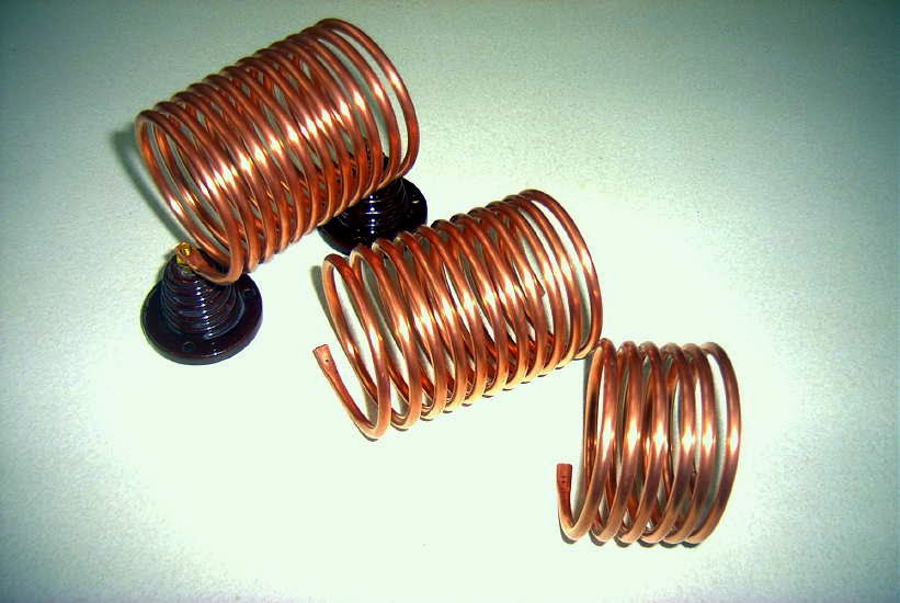
I've now completed a set of tank coils for the new'29 MOPA project. These were wound with 3/16" copper tubing which has become very difficult to source. Luckily, after much searching, I was fortunate enough to find several rolls locally at a very attractive price. Although I do see it quite often on e-bay, sellers either refuse to ship to Canada or their shipping charges are far too high to make it worthwhile. The larger 1/4" rolls are still readily available, but for any given inductance, will take up a lot more room on the breadboard if space is an issue.
These coils cover the amplifier tank, the Hartley oscillator's tank, and the antenna coupling link. Respectively, the coils measure 4.9uH, 4.0uH and 1.9uH.
Winding these is always fun but the method used requires that the needed length be predetermined and cut from the roll beforehand. The first time I did this, when building my TNT transmitter, I learned the hard way to always add at least another foot to cover the additional length eaten-up by turn-spacing and for coil end flattening and mounting.
While visiting Vancouver for a few days I was able to find a couple of pieces needed for my non-line of sight (NLOS) lightwave experiments.
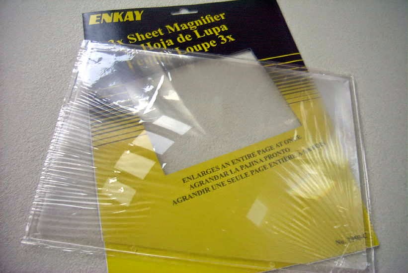
I purchased a nice 4.25" magnifier lens, with suitable focal length, as well as an inexpensive page-size fresnel magnifying lens. What is particularly pleasing is that the fresnel is a rigid lens, about 2 mm thick, unlike most page magnifiers that are thin and floppy. I have yet to test its blur circle or determine its focal length.
I plan to use one or the other of these lenses in a small, portable lightwave receiver module that I can carry to the other side of the island to listen for the main large transmitter, aimed slightly above the horizon, in beacon-mode. If the smaller fresnel does the job, it will be an inexpensive source for anyone else needing a simple lens for either transmitting or receiving.
If the deep-red light tests prove successful, I'll switch the system to IR light but at this stage I'm not sure how focusing and optimizing receivers and transmitters can be done with a light source that is essentially invisible? Perhaps using an IR source that is right on the edge of deep-red will still have enough visible light to allow finding the optimum focus more easily.
More information on NLOS experiments can be found in Yahoo's Optical DX Group as well is in G3XBM' s 481thz blogs.
As well, anyone in the Vancouver lower mainland (as far as the northern Sunshine Coast area) that might be considering lightwave ... I'd love to work you! Pretty well any high spot in this region is direct LOS for me.
Lightwave Article From ‘TCA’
 |
| VE7SL Backyard Test |
VK4EBP’s NLOS Lightwave Experiments – Part 3
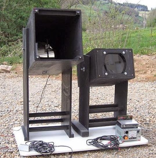 |
| F1AVY's Cloudbounce System |
"Returning to Steve's questions and our general discourse:
..is it (the RX) fairly small and portable...and lensless?
I do have a lens in the RX I now prefer to use - although it happens to be a convex lens from a tabletop magnifier - about 7x12cm giving me a narrow reception beam and a fair bit of gain compared with naked photodiode. There seems to be a general agreement that increasing the size of receiving aperture will capture more light and is the best way to greater gain.
Here I need to qualify gain requirements for my particular applications. I am currently exploring relatively short-distance NLOS paths in urban environments with abundant QRM from city and suburban lights, and this already limits my gain requirements. I developed my own qualitative test of satisfactory sensitivity - by pointing my receiver at individual stars in the sky. If I can hear them twinkle (yes they do twinkle!!!) then I am generally satisfied with the project.
On cloudy nights, pointing the RX into the clouds brings an interesting combination of mains harmonics and general hash from neon lights, clicking pulses from aeroplane lights, sweeping sounds from airport and marine lighthouses. In an environment like this, going to extreme lengths as one would do for very long-range cloudbounce or LOS comms in dark and secluded areas is simply not required and uneconomical. I initially did invest time and money in large receiving boxes with the best components there are, only to find that, unless I moved out into the bush, I could not take a real advantage of the improved performance, and did equally well with smaller and more wieldy portable designs.
"Is the idea, when talking about NLOS, to light up as much sky as possible...and that is why no focusing lenses are employed? Would a focused emitter, as produced by the typical Fresnel lens light box, produce too narrow a beam than desired? It would seem likely that with precise aiming combined with the gain to be had by utilizing fresnels (for example), would produce longer paths??"
There are several separate issues there. One is the implied requirement for a large Fresnel lens in order to obtain a narrow beam. First, how narrow is narrow enough? If we can be satisfied with say +- 5 degrees then there are more wieldy solutions available - most of the high power LEDs now have clip-on small spot lenses awailable separately - usually from third-party manufacturers. These were unheard of until recently. Standard-sized LEDs are available with very narrow radiation pattern, e.g. the SFH4550 at barely +-3 degrees. And one would expect an array of 200+ of them to behave quite like our stacked Yagis, many times over! Hence narrow beam is quite possible even without an external lens.
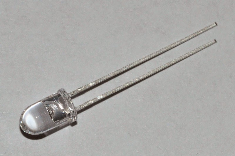 |
| Osram SFH4550 IR LED |
Of course the extremely narrow beams that one would prefer for LOS DX comms would be next to impossible to align in NLOS situation. (Invisible infrared is not a problem in LOS as it can be easily supplemented with e.g. a plain strobe light for alignment purposes.) I find my +-3 degrees array (with similar +-3 deg aperture at receiving end) hard enough to align over the horizon, and it is probably the limit of how narrow one can go to remain practicable in NLOS.
"to light up as much sky as possible..."
It is possible that cloudbounce and obstruction-bounce will develop into separate NLOS techniques, along with atmospheric scatter. Of course one can think of all of these in some topographies.
I had some success in inter-suburban cloudbounce with high beam elevations at both ends - 30 to 60 degrees. Also with 45 degrees or less elevation with TX and RX about 1km apart side by side and pointing at the same cloud in the distance. Power used around 10-20W, beamwidth +-5 to 10 degrees, red and infrared with similar results (including 950nm). The received signal was just strong enough for telegraphy or qrss, but never near enough for any type of voice modulation. Results were affected by the height of cloud cover necessitating frequent elevation adjustment, and an additional liaison channel on VHF. Signals disappeared entirely as soon as the clouds started producing rain.
I never got any usable results with clear night sky and the TX and (imaginary) RX beams crossing each other at similar elevations. Only at very close distances - the best signals being received with blue and infrared. Presumably Rayleigh scatter with blue. (This raises the possibility of usable atmospheric scatter with UV?)
Only recently I commenced preliminary tests with close-to-ground, low-elevation NLOS and immediately the infrared proved itself to be a clear winner with quite reliable and repetitive results. (Needless to say the signal strengths are marginal compared with direct LOS over similar distance.) Intuitively, one would suspect general scatter and bouncing of nearby objects being the main sources of some of the energy reaching over the horizon, with some contribution perhaps of atmospheric/dust/aerosol scatter.
This adds an additional dimension to your question.. to light up as many objects around the TX(or around RX, or around the obstruction) as possible, or send the focused beam as far as possible? I guess it will very much depend on topography. I can imagine a situation where I would prefer to use a broad floodlight rather than a focused beam - e.g. to illuminate as many as possible of the surrounding tall buildings if transmitting from a ground floor apartment. Or from the foot of a mountain. An opposite rule would apply if it is the receiver that is just behind an obstruction - here a focused TX beam and a broad RX aperture might prove advantageous. And where the main obstruction is midway between TX and TX than the usual narrow-beam configuration would apply at both ends. I think it might be worth trying an infrared TX with interchangeable lenses, and same for the RX...
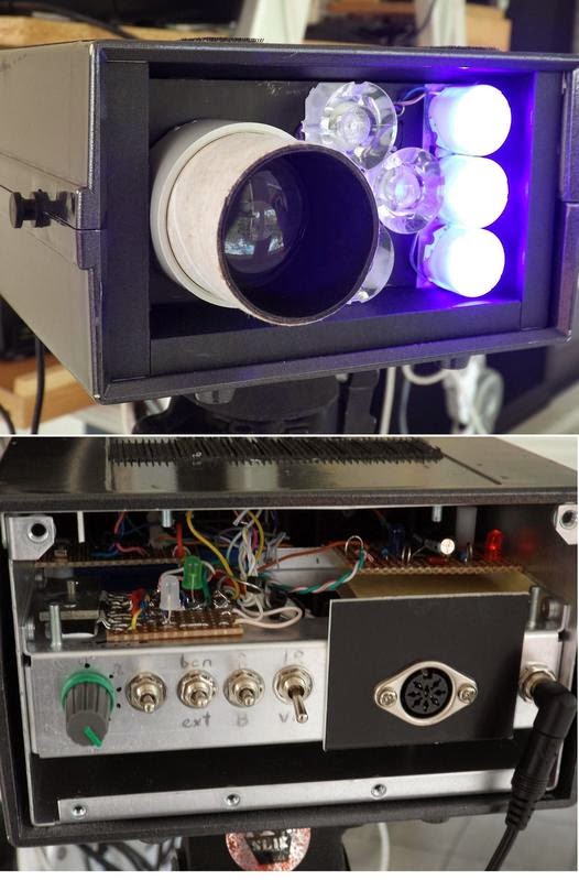
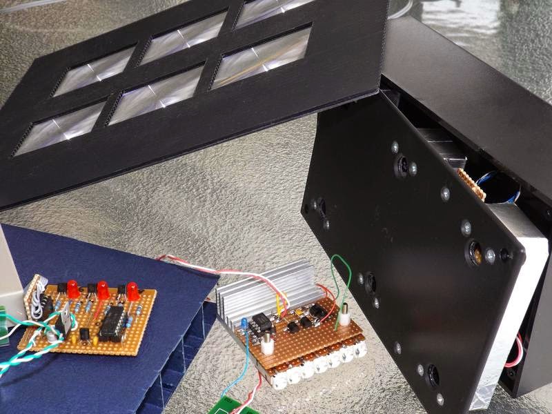
The portable TRX image shows the general view. Most of the electronics is contained in a plastic box and includes an SLA battery, the RX audio bandpass filter, power amp and speaker, and most of the PWM AM TX circuitry except the final LED driver. The DIN socket provides connection to external RX front end TX output drivers and LEDs, usually held together on a tripod. The header socket is for the external microphone connection, and there are switches for power and speaker and a headphone jack. The crudely made corflute box beside it is the RX front end with lens, photodiode and preamp.
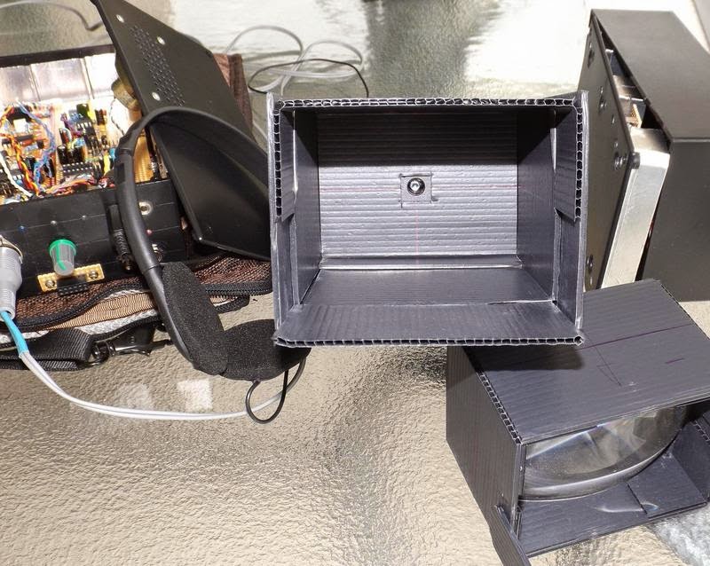
The RX detail 01 shows the business end of the photodiode, and the separate lens box (slides in and out for focus adjustment). Detail 02 shows the preamp with interchangeable photodiode modules - SFH213 for visible to 850nm, and the SFH213-FA for 850nm and below.
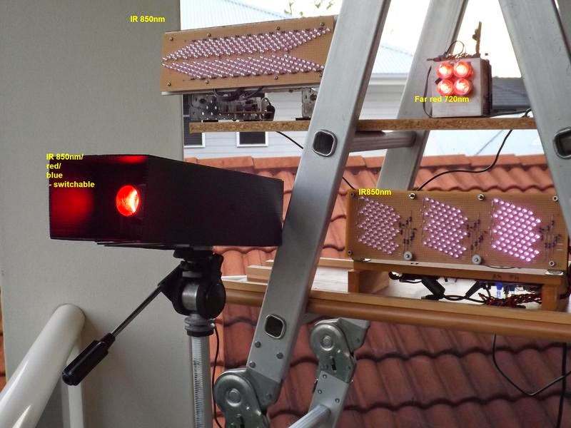
Multi-wavelength TX 01 (front and back image) includes several groups of fat LEDs (red, blue and 850nm) with matching lenses providing approx. +-5 degrees apertures. Also the PWM driver on 2x CAT4101 in parallel, external high current power connection, intensity control, and a PICAXE-controlled strobe or audio callsign/frequency sweep beacon.The whole assembly connects to the TRX control box (above) and can provide power to it, draw power from it, or have both DC sources in parallel.Enclosure includes a photo tripod mount on the bottom plate, and velcro strips on top to hold the RX front end.
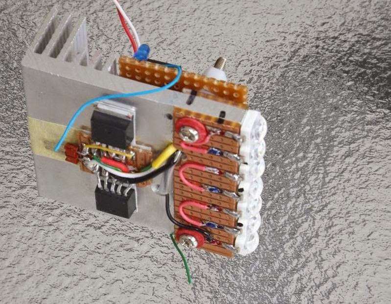
Pocket-sized 10W IR TX is a small holiday project and still work in progress. The 7x LEDs are 2W each SFH4783 with an intrinsically narrow beam of +-10 degrees - quite appreciable for a naked LED of this size and possibly obviating the need for external optics in some applications. My usual CAT4101 drivers are included and capable of providing 2A at 50% duty cycle. Another Picaxe beacon is on the other side of the heatsink, and the voice modulator is still in progress.
The low-power multi-wavelength TX is another one day project, built to compare relative performances of 850 and 950nm IR. Three almost identical beams of red, 850 and 950 are transmitted in sequence with approx 100mA PWM running each diode. Unique CW ID has been coded for each wavelength.
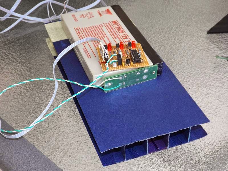
6x SFH213 photodiode with individual preamps - quite a respectable low noise, high sensitivity front-end that works very well without external optics (SFH213 have a +-10 deg intrinsic apertures). A matching array of small fresnel lenses has been built and tested for narrow-beam reception, but a permanent box is yet to be added.. Some of the other gadgets seen in the foreground."
As mentioned earlier, Jan's experiments with NLOS signals utilizing IR is of particular interest to myself as I would like to continue experiments with VE7CA, on the other side of Georgia Strait...hopefully with Markus not having to move to a LOS position, but simply aiming across the Strait in a direct path, from his yard. Using Argo and QRSS3 mode, it will be interesting to see if any signals can be recovered from the cloud bottoms on some overnight runs.
More information on NLOS work may be found on the Australian Optical DX Group in Yahoo Groups as well as in the UK Nanowave Group....why is it that these two countries have so much homebrew fun??,,,and don't forget Clint's (KA7OEI) superb Optical Communications / Moduulated Light pages!
VK4EBP’s NLOS Lightwave Experiments – Part 2
 |
| Courtesy: http://www.ledsmagazine.com |
"Visible LEDs and optics: Some of my favourites include the LZ1 and LZ4 series from LedEngin used with matching spot lenses, or thick condenser lenses from old visual projectors. Also various Golden Dragon varieties with matching small plastic spot lenses. Average beam divergence with either configuration is about +-4 degrees. (Happy to provide detailed parts numbers.)
Infrared LEDs: Here we have a some good products from Vishay (TSHG series), with narrow beam (some go down to +-2 degrees) in the standard 5mm packages and max current of 100mA.

They can make nice pencil-beam arrays in combined series/parallel with 200 or more LEDS and no optics required, at less than 40c per LED. Lots of soldering though :). For the 950nm range (not extensively tested yet) the Vishay TSAL range of LEDs will do nicely.
LED drivers: I found a very neat IC to PWM-drive the LEDs at up to 1A - the CAT4101 from ON Semiconductors.
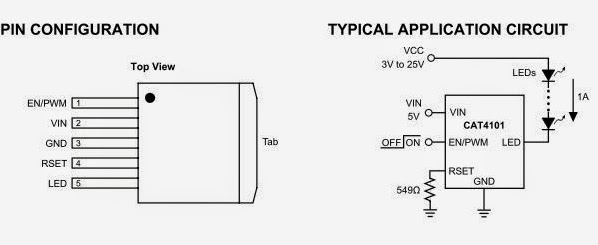
Usually have two in parallel for a peak of 2A at 50% duty cycle, giving me 1A average to drive the LED string.
At the reciving end I am now using a preamp loosely based on Clint's no-feedback design with some hum filtering and other post minor post-processing feeding to an audio amp, or to SpectrumLab."
"...tonight I am trying to compare 830nm against 940nm on a 600m short NLOS path. For this, I have just built a small TX with two "naked" LEDs - TSAL6100 (940nm) and TSHG8200 (830nm). Both have identical shapes of their radiation patterns with +-10 degrees. Each mounted inside of a square cross-section black cardboard tube side by side to ultimately give them a very uniform square beam of approx +-4 degrees. Each driven with 440Hz square wave at 100mA with unique morse identifier for each.
There is a third visible LED as well with its own cardboard collimator and morse ID, to serve as aiming tool and a kind of reference.
The purpose is to see whether 940nm would offer additional advantages in NLOS situations, due perhaps to better/different reflection, scatter, refraction or whatever physical processes might be involved.
An additional advantage might be removing my setup further away from visible light pollution. With the growing popularity of LED lighting in both household and the industry we are having a chance of less and less infrared pollution from traditional incandescent or similar sources - and making light comms more practical in urban environments - all with a simple IR filter at the receiving end.
Tonight's tests were not as productive as anticipated, but somewhat educational nevertheless. First of all the receiving location I picked on the map suffered from severe QRM from sodium street lights. I picked strongly all my "big" IR transmitters, but the visible and the "naked" ones were lost in the QRM, if present at all. I returned home, pointed the 150mW TX into nearby bushland and went for a walk. The red light reception vanished immediately after loosing sight of TX, followed quickly by the 940nm with the 830nm persisting the longest up to perhaps 100m - with the beam fired parallel to ground from upper storey into the crowns of the trees. Reception required pointing the receiver slightly up, intersecting the TX beam somewhere in the tree branches.
Briefly - I confirmed what I already knew: - IR is far superior to visible for NLOS work - indeed visible light is of no use.
- Low elevations and scatter from ground objects is superior to high beam elevations.
A new observation (that I would like to confirm) is that 900+nm is not worth bothering about. It is known that 950nm suffers from greater scatter in atmospheric particles than 850, but this proved to be more of a hindrance than help in NLOS work.
Another practical observation is that the 950nm version of the common SFH213 photodiode (SFH213-FA) works very well in receiving 850nm whilst filtering out lots of the visible pollution (well, perhaps except the sodium lamps!).
I started tonight's session before sunset and got very good NLOS reception of my large IR TXs - in what could be described as quite a bright twilight. (I carry two plug-in front-end modules each with one of the two photodiodes and the input FET.)
Another holiday project - a pocket-sized 10W TX! I found new IR LEDs - SFH4783 - rated at 2W, barely 1.65V of Vf, and intrinsically narrow angle of +-10 degrees. This means no optics, and up to seven of them in series on a small heatsink can be run from a 12V SLA battery.
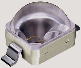 |
| Osram SFH4783 |
This reminds me of yet another observation - out of my several large 850nm TXs the best performers are the naked narrow-angle multiple LED arrays - and the one containing 3 high power broad-beam LEDs with spot optics performing the worst. Well the lenses are designed for visible LEDs and I have no guarantee that the material refraction angles and loses are acceptable in the IR range...
Returning to Steve's questions and our general discourse:
..is it (the RX) fairly small and portable...and lensless? (cont'd)...
VK4EBP’s NLOS Lightwave Experiments – Part 1
Jan's posting was chalk-full of useful "hands-on" information and was just what I needed to hear and led to some extensive and interesting conversation, well worth passing on to others. I could summarize Jan's work in point form but I think it is more interesting to let Jan describe it himself.
"Finally some success with over-the-horizon light. Briefly - several transmitters of several watts each were fired
simultaneously with the beams aimed at the tops of nearby trees, each
transmitter sending unique combination of tones (direct AM).
 |
| Osram SFH213-FA |
plastic lens approx. 7x12cm. Receiver was aimed towards the TX site and
pointed just over the horizon.
Aural reception of 850nm infrared signals was very good. There was no
trace of TX signals in visible or near-visible spectrum. Signal quality on
850nm was further improved with an infrared-filtered photodiode (SFH213FA, 950nm peak) which provided some attenuation of suburban lights QRM.
My earlier series of experiments over the years was aimed at achieving NLOS short-range communications in a light-polluted metropolitan
environment. I had limited successes with high-elevation cloudbounce over
several km distance using both red and infrared. Very poor results with
high-elevation scatter in clear air, with blue light appearing the best,
and green and yellow the worst for the purpose. More recent tests
suggested that low elevations with infrared light offer a reliable link,
and today's results seem to confirm that.
More to follow! 10km test tomorrow night. 73 de Jan vk4ebp"
Jan has been testing several different TX emitters / wavelengths, simultaneously, each with a different CW identifier. His path started with a 1km hop through his local residential neighbourhood, with significant obstructions shown below. Later the path was stretched to 10km. His observations involving IR were particularly helpful:
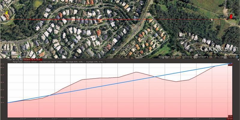 |
| 1km NLOS Path |
deep red 10W with condenser lens, 3x1W Golden Dragon 850nm IR LED with
+-4deg spot lenses, and 3x 4W LZ1 blue with +-5 deg spot lenses. Manually
switchable by my very patient family members on request via walkie talkie
from the receiving site. The two multi-LED arrays are approx 10W each in
total, one containing a multitude of +-3 deg SFH4550, and the other
+-10deg some other LEDs - do not remember after many years since building it. The small heatsink block contains 4x LZ1 far red, run at about 8W
total."
"At the NLOS location 1km away I was able to copy all the 850nm TXs and
none of the visible/borderline ones.Last night I tried 10km distance.
The topography is theoretically line-of-sight, but isolated from the receiving site by a thick bushland in nearby park. I was firing the transmitters about 3 degrees above what
would be line of sight, thus having about half the beam into the air and
another half scattered in the tree tops near the TX site.
I was able to weakly copy only one of the transmitters - the array of 200 or so of the +-3deg IR LEDs. At the moment I am not certain whether it was from atmospheric or tree scatter.
From earlier tests I observed that IR penetrates very well into the bushland, long after the visible beams were lost both visually and electronically. Similarly, it seems to propagate well into suburban
streets. Presumably the longer wavelength is "seeing" rough surfaces like tree trunks and brick walls as actually shiny and reflecting...."
".... a bit more about my transmitters. (cont'd....)


