Posts Tagged ‘LF’
 The FA-VA4 Vector Antenna Analyzer (LF-100MHz)

For some time I had been considering the purchase of the MFJ259 antenna analyzer but after a little online sleuthing, came across this little beauty, the FA-VA4 Antenna Analyzer by Funk Amateur in Germany and available through their Box73 website here.
I liked the fact that the cost of the analyzer was about half that of anything else comparable ($140 US including shipping) and that it covered the new 2200 / 630m bands!
I think many amateurs planning on building a system for either of these new bands will find the very affordable FA-VA4 a handy piece of equipment when it comes to working on their LF / MF antenna since most available SWR meters do not cover these frequencies accurately.
Delivery time was fast and everything was very well packaged. The FA-VA4 comes in partial kit form and requires only a short amount of time to put together.
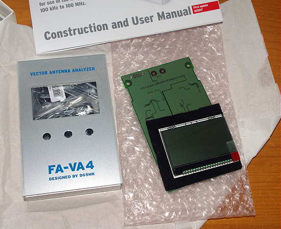
The necessary assembly consists of soldering pin strip connectors, switches, AA cell holders, and the BNC connector. All of the tricky SMD components have been pre-mounted ... total assembly time was less than 60 minutes and everything fired-up nicely, without problems, thanks to the well written instruction / user manual.

Included with the kit are three BNC connectors needed to calibrate the instrument for the highest accuracy. These consist of a 'Shorted' connector, an 'Open' connector and a 50 ohm 'Load' connector (SOL). A simple three-part calibration procedure for all frequencies takes about 15 minute to complete, while the instrument calibrates itself as it scans through all frequency ranges with each connector plugged into the output. Once this task is completed, the analyzer is ready for use.

If you're like me, I think the main use will be to check out and tweak some of your HF antennas using the SWR or Z sweep function. This allows you to set a desired 'center' frequency along with a + / - sweep range and have the display draw a nice plot of your system.
Had my 630m antenna not already been tuned and matched, I would have found the analyzer to be a great help but, thanks to my 'scopematch', that antenna has already been optimised.
All menu features and data entry is via three momentary-contact push switches. Although this might initially seem awkward, it is not, and operation is pretty intuitive.
The main modes of operation are:
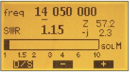
Single Frequency SWR Measurement
 |
| courtesy: http://www.box73.com/product/5 |
Single Frequency Impedance Measurement
 |
| courtesy: http://www.box73.com/product/5 |
Single SWR Measurement Run
 |
| courtesy: http://www.box73.com/product/5 |
Single Run For Impedance Measurement (Resistance and Reactance)
 |
| courtesy: http://www.box73.com/product/5 |
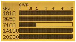
SWR Measurement On Five Frequencies (5 Band Measurement)
 |
| courtesy: http://www.box73.com/product/5 |
As well, all of the above can be viewed in a continuous 'cycle' mode, as inputs are changed and all screens can be saved for future reference.
Additional capabilities include use in an HF Signal Generator Mode (~ 1V square wave @50 ohms), the ability to measure C and L at a given frequency, as a 'dip meter' and to measure cable resonances and determine lengths.
The complete manual may also be downloaded from their website here.
I will soon put all of my antennas to the test and see what work might need to be done to optimize them, particularly my HF half slopers, which, in spite of their great performance, have always proven a bit of a mystery when it comes to pruning them to resonance ... I rather suspect that the sloping wires are more of an impedance tuning stub than a radiator and that most radiation comes from the vertical support tower, not the sloping wire.
All-in-all, the FA-VA4 appears to offer very good value for the money and is a well built, quality test instrument. I think it will become a popular choice among hams, especially those on LF / MF. The only thing different that I would have liked, would be to have a UHF (SO 239) connector rather than a BNC on the output, since most amateurs are using these on their HF systems ... or, the inclusion of a BNC-to-UHF adapter.
If you already use this device, please feel free to add your comments below!
LF Tests From WH2NXD / NI7J
For those of you with an interest in amateur LF work, you may be interested in the upcoming WSPR test transmissions from Ron, WH2XND / NI7J, located in Phoenix, Arizona.
One of Ron's several experimental licences allows him to run as much as 10W ERP from 68-76 KHz. To generate this amount of ERP at 75 KHz requires a lot of power and I suspect that he will still be well under his licence limitations ... amateur-sized antennas are just not very efficient on these low fequencies.
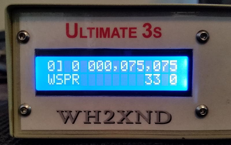
Previous experiments a few years ago, at lower ERP, produced impressive results, as shown by one of the WSPRnet maps for an overnight session on 75.075 KHz.
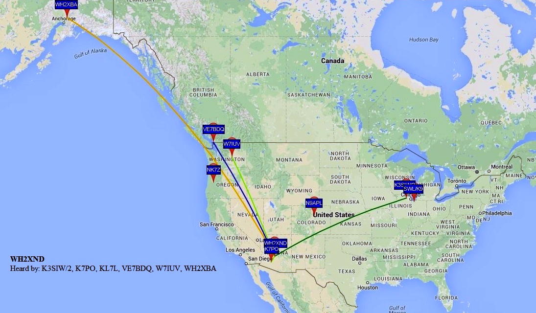
Ron used one of the Hans Summers U3S transmitters to generate his LF WSPR signal, amplifying it with a 400W Hafler audio amplifier. This winter's tests will be at 800W, with a W1VD FET amplifier designed for VLF.
Ron's experimental licence also covers 470 - 495 KHz at a whopping 100W ERP and 130 - 140 KHz at 50W ERP ... some serious power.
You may also find Ron's interesting and well-illustrated website description of some experimental antenna work that he has been doing on MF, LF and what it takes to resonate a typical Marconi 'T' on these bands.
 |
| MF- LF 'T' Antenna At WH2XND |
 |
| 75 KHz Loading Coils! |
Ron has tentatively chosen late November or early December for his 'almost' VLF tests and when the date and frequency are finalized, I will post the information here on the blog.
Getting Started On The New LF and MF Bands
 Finally the long wait is over! The LF 2200m band and the MF 630m band have finally arrived for amateurs in the USA! I'm sure most of you have read the fine print regarding deployment of the two bands, but if not, here is the ARRL's recent announcement.
It has been a very long wait for the FCC to implement these bands after they were approved for amateur use in 2007 and 2012 at the World Radiocommunication Conferences in Geneva. Canadian amateurs have had 630m since 2014 and 2200m since 2009 ... in the meantime, we have been anxiously awaiting the arrival of American amateurs to liven things up and to garner new interest in these bands.
Before operating on these bands, amateurs in the USA are required to register their intent via a simple web form found here on the Utilities Technology Council's website. Then follows a 30 day waiting period during which the UTC will check out your location to be sure that you are not located within 1km of any power lines that might be carrying LF or MF PLC (Power Line Carrier) control signals. If you hear nothing back from UTC within 30 days, you are good to go.
A positive outcome of registering via the UTC form is that there can be no PLC signals implemented on the lines near you at a later date! By registering your intended operating location(s), you are locking-in these spots for no further PLC development. If you have an EOC or Field Day site that you think you may want to operate from at some point, register these as well.
I think it is important that even if you do not intend to operate on either of these bands or perhaps a few years down the road, that you register as soon as possible ... the fewer PLC signals operating close to or within the amateur radio spectrum, the better, and this is one way of furthering that goal.
There has already been a vast amount of published information on both of these bands, describing transmitters, receiving systems and transmitting antennas so I won't go into much detail here regarding these topics ... and besides, it's always very interesting to search these things out yourself, learning as you go. Be assured that either of these bands will present interesting new challenges not encountered in typical HF operation, but all of the basic principles you are used to still apply ... it's just that things are much bigger down below the broadcast band!
Far and away, the best source of information for US amateurs can be found on John Langridge's (KB5NJD) NJDTechnolgies website. John has been operating on MF for several years already with an experimental licence (WG2XIQ) and is more than an expert on this topic.
His daily blog includes a detailed account of worldwide activity on 630m and makes for fascinating reading. His website provides all of the information and valuable links that you might need to plan your own LF or MF station. The information on his site, if printed out, would make a wonderful LF / MF Handbook!
My own blog and website also contain much helpful material, with a particular emphasis on Canadian activity on these bands. All of my blogspots dealing with 630m can be found here and contain enough bedtime reading to keep you busy for many nights.
If you are thinking of getting on either of these new bands, particularly 630m, here is a short Q & A that may help you through the initial planning stage of how to get started.
What modes are commonly used on these bands?
At present, due to the low level of two-way amateur radio activity, the WSPR mode has been dominant. This is a weak-signal 'beacon-only' mode so most two-way contacts take place either on CW or on the weak signal JT-9 mode. JT-9 has been specifically designed for HF and LF / MF weak signal two-way work and can dig as deep as -27db into the noise to provide a contact that could never be completed on other conventional modes such as CW.
With the influx of new activity on these bands, particularly on 630m, I expect that most two-way work will equal or surpass the amount of WSPR activity and that JT-9 and CW will do most of the heavy-lifting.
How far can I work on these bands?
Although the erp limits appear to be QRP-sized, this is somewhat misleading ... it is astonishing what can be done. Don't think that '5W eirp' means that you can only run a transmitter capable of generating 5W. Because antennas are so inefficient on these bands, it is often necessary to run several hundreds of watts in order to achieve the legal eirp limits. The bigger and more efficient your antenna, the lower the power needed becomes. On many nights, 5W eirp will get you clear across the country on MF.
However, if you build something for 630m that only produces 25W of power, you will still have the capability of working many stations in other states on most winter evenings or mornings, as propagation, the 'great equalizer', can be amazing at times.
Presently, most stations operating on WSPR will often be detected from one coast to the other and those with excellent locations near the coast will soon be working stations down under or in Europe, either on CW or on JT-9. If you can, design and build for the maximum eirp, 1W on 2200m and 5W on 630m.
What type of transmitter do I need?
If your interests are only in CW, then the sky is the limit when it comes to design. There are numerous simple solid state transmitter designs out there, using inexpensive FETs to generate power. I'm hoping, along with many others, that there will be a considerable amount of CW activity on 630m and even a simple 25-watter should provide you with lots of fun. There may also be some appetite for QRSS CW which can give the weak-signal digital modes a run for their money while still using a simple transmitter.
If you are interested in digital modes, such as WSPR or JT-9, the easiest way is through the use of a transverter to take care of converting your HF transceiver's capabilities to LF or HF. There are presently a few commercial transverter options available and can be found on the NJDTechnologies links page.
A good choice is the inexpensive 630m transverter produced by John Molnar, shown below and available both as a kit or prebuilt. It works well and is very popular.
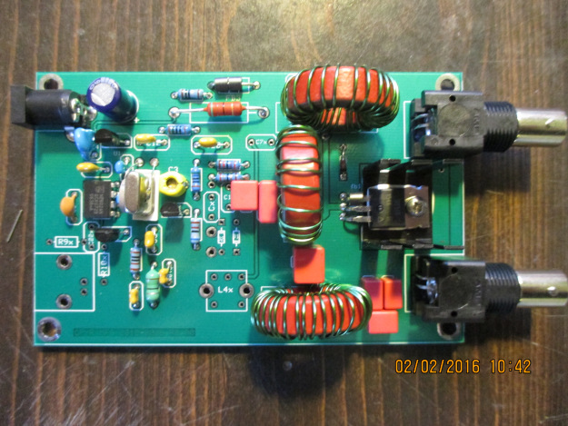 |
| 630m Transverter - John Molnar WA3ETD / WG2XKA |
 |
| G3XBM -630m Transverter |
If you want something in the 'Collins category', the tranverters (both 2200m and 630m models) produced by VK4YB's Monitor Sensors provide around 70W output and are incredibly well designed and built. I have been very happily employing a 630m model for well over a year now ... my review of the transverter can be found here.
 |
| VK4YB - 630m Transverter |
I would like to put on a beacon. What do you suggest?
The best and most informational type of beacon is a WSPR mode beacon. A WSPR beacon operator can always determine where his beacon is being heard, in real time, along with how well it is being heard, by watching the uploaded 'spots' of his beacon on the WSPRnet. You will have much better coverage with this weak-signal mode beacon compared to one on CW ... for every CW report received, you would likely get ten times or more that number on WSPR.
Although WSPR is a great mode for checking out propagation, it's very easy to get into the habit of nightly beaconing and not developing your station any further. If you do run a WSPR beacon, be sure to try some of the other two-way modes such as CW or JT9 and call CQ regularly ... ham radio is all about making two-way contacts!
I don't have enough property for the large antennas required, so I won't be able to use these bands.
Even if you are limited in space, you can still enjoy these bands. There are many examples of stations on small city or suburban-size lots that are consistently heard across North America on 630m. If you have the room for an 80m or 40m dipole or inverted-L, that will be enough space to work these bands. An inverted-L for example, can be base-loaded and tuned to resonance. Along with several ground radials, even a small antenna system like this will allow you to work skywave DX or be heard across the country when propagation is good. I'm constantly amazed at how well these bands propagate with very low amounts of erp. Don't let living on a small lot stop you from exploring these bands!
All I hear is noise on these bands ... how can I use them if I can't hear anything?
Growing noise floors are common to everyone and this is often the biggest challenge for LF and MF operators, especially those in densely populated regions. Armed with a little knowledge and investigation, oftentimes seemingly impossible QRN can be substantially reduced if not eliminated entirely ... even easier when the noise source is found to be in your own home! While some amateurs just give up at this stage, most will see it as an interesting challenge to be overcome and part of the many learning experiences offered by these new bands.
In addition to the informational links provided above, I have just added a new 'Getting Started On 630m' page to my website. This page has a two-part article that I recently wrote for The Canadian Amateur, our national amateur radio journal. The articles describe a simple way of getting on 630m CW as well as providing some basic antenna information and ideas.
This blog also has extensive writings involving 630m over the past few years, describing equipment used and suggestions for new operators, much of it involving homebrewing. There are several links on the right that will take you to specific blogs dealing with 630m.
For present LF and MF operators here in Canada, the arrival of our American friends to these bands is generating much excitement and anticipation. The opening of these bands in the USA will pump new life into this part of the spectrum for all North American participants and the opportunities for homebrewing and experimenting are boundless. It should be a very exciting winter!
If you have not taken the 60 seconds required to register your station on the UTC webpage, please don't neglect to do this via the link provided above. There have, reportedly, been thousands of amateurs doing this already, as it effectively locks-out their locations for any future PLC deployment that might keep them off these bands at a later date.
See you in mid-October on 630!
LF / MF News From Monitor Sensors

A note from Roger, VK4YB of Monitor Sensors, reports some interesting news.
You might recall that his company manufactures a very versatile and well-engineered 630m transverter which was used at both ends of our two 630m JT9 contacts last year during the fall equinox propagation peak between North America and down-under.
Roger now reports that Monitor Sensors will be producing a new 2200m transverter, with all of the bells and whistles found on the 630m unit which has proven to be a real workhorse.
Monitor Sensors 2200m Transverter
The Monitor Sensors TVTR2 2200m Transverter enables any Amateur Radio Station, equipped with a conventional HF transceiver, immediate, all mode, access to the new 135.7-137.8 kHz, 2200m band.
The receiver design incorporates a 7pole Chebyshev filter, 3kHz wide roofing filter and a 5 pole Chebyshev filter in cascade before the double balanced, commutating mixer, fed by an ultra stable, temperature compensated, extremely low phase noise, MEMS local oscillator. The mixer is followed by a Chebychev band pass filter into an ultra linear, low noise, current feedback, IF amplifier. The receiver noise floor, in a 500Hz bandwidth, is -125 dBm and yet the onset of compression is not reached until +11dBm. A front end 20dB attenuator can be switched in for even higher signal handling. Overall receiver gain is set to +6dB, or -14dBm with attenuator in.
The transmitter input circuit incorporates a 0-14 dB switched step attenuator to prevent over driving. The same mixer and local oscillator are used on the transmit side. The PA uses 6 rugged lateral FETs in class AB push-pull to easily achieve the 50 watts rated output. Lateral FETs are inherently linear and thermally stable. The transmitter can be run at full power, indefinitely, into a dead short or open circuit without any danger of damaging the FETs. Transmit-receive switching is automatic with user selectable VOX delay. Alternatively the PTT line may be used.
The transverter employs extensive and accurate metering. Power input and output, SWR, Frequency, Attenuation in use, Temperature, Supply Voltage, Current and Resistance are displayed.
Transmission is inhibited if carrier frequencies outside the 135.7-137.8 kHz band are detected. A tuning screen may be selected which displays SWR in digital and graphical form for easy antenna adjustment. The menu system is self explanatory and users report no manual is needed, although one is supplied. A USB socket is provided for future code upgrades (free of charge) from the Monitor Sensors web site.
The transverter has been designed for the best possible protection against accidental mishaps. It will survive reverse polarity supply and the injection of 100 watts of HF into any of its ports whether in transmit or receive mode. If supply current exceeds 25 Amps, the supply is cut in 3 microseconds. This electronic breaker can be reset by simply switching off and on again. The transmitter will shut down in the unlikely event that the internal heat sink reaches 90°C. The cooling fan is under the proportional control of the microcomputer and begins operation above 35°C. Any unusual operation will cause the screen to turn red and an appropriate warning will be displayed.
TVTR2 Specifications
RF frequency range 135.7 to 137.8 kHz
IF frequency range 1805.7 to 1807.8 kHz (others available in the 160m band)
Transmission modes CW, SSB, WSPR, and all other data modes
Output Power 50 Watts Continuous, 100% duty cycle @13.8V supply
Input and Output Impedance 50 Ohms
Supply voltage 13.8 VDC @ 15 Amps nominal, 10-16 VDC operational
Rx noise floor -125 dBm (500 Hz bandwidth)
Rx 3dB compression point +15 dBm (Rx attenuator out)
Rx IF rejection better than 75dB
Rx conversion gain +6dB nominal
Roofing filter in-band ripple +/- 0.5dB
Tx 3rd order IMD -33 dB below PEP, typical at 50W output
Tx 5th order IMD -45dB below PEP, typical at 50W output
Tx harmonics and spurii All better than -50dB
Tx conversion gain +10dB nominal
Power input connector 2 * Anderson Power Poles (one Power cable supplied)
RF connectors 3 * SO239 (one PL259 to PL259 cable supplied)
PTT connectors 2 * RCA (one RCA to RCA cable supplied)
USB connector Micro B USB, (matching cable supplied)
Dimensions 12½ * 4¼ * 3 inches, 320 * 120 * 76 mm
Weight 3.4 lbs, 1.6 kg
In addition to the transverters, Monitor Sensors will also be manufacturing solid state amplifiers for both the 2200m and 630m bands with power levels at around the 450W output level. Like the transverters, these will be 'linear' devices as well. It is possible that a duo-band amplifier will also eventually be produced.
It will be interesting to see if any other new gear becomes commercially available from other manufacturers once the LF / MF ham bands are introduced in the U.S.A. , something that is expected to happen fairly soon.
LF / MF News From Monitor Sensors
A note from Roger, VK4YB of Monitor Sensors, reports some interesting news.
You might recall that his company manufactures a very versatile and well-engineered 630m transverter which was used at both ends of our two 630m JT9 contacts last year during the fall equinox propagation peak between North America and down-under.
Roger now reports that Monitor Sensors will be producing a new 2200m transverter, with all of the bells and whistles found on the 630m unit which has proven to be a real workhorse.
Monitor Sensors 2200m Transverter
The Monitor Sensors TVTR2 2200m Transverter enables any Amateur Radio Station, equipped with a conventional HF transceiver, immediate, all mode, access to the new 135.7-137.8 kHz, 2200m band.
The receiver design incorporates a 7pole Chebyshev filter, 3kHz wide roofing filter and a 5 pole Chebyshev filter in cascade before the double balanced, commutating mixer, fed by an ultra stable, temperature compensated, extremely low phase noise, MEMS local oscillator. The mixer is followed by a Chebychev band pass filter into an ultra linear, low noise, current feedback, IF amplifier. The receiver noise floor, in a 500Hz bandwidth, is -125 dBm and yet the onset of compression is not reached until +11dBm. A front end 20dB attenuator can be switched in for even higher signal handling. Overall receiver gain is set to +6dB, or -14dBm with attenuator in.
The transmitter input circuit incorporates a 0-14 dB switched step attenuator to prevent over driving. The same mixer and local oscillator are used on the transmit side. The PA uses 6 rugged lateral FETs in class AB push-pull to easily achieve the 50 watts rated output. Lateral FETs are inherently linear and thermally stable. The transmitter can be run at full power, indefinitely, into a dead short or open circuit without any danger of damaging the FETs. Transmit-receive switching is automatic with user selectable VOX delay. Alternatively the PTT line may be used.
The transverter employs extensive and accurate metering. Power input and output, SWR, Frequency, Attenuation in use, Temperature, Supply Voltage, Current and Resistance are displayed.
Transmission is inhibited if carrier frequencies outside the 135.7-137.8 kHz band are detected. A tuning screen may be selected which displays SWR in digital and graphical form for easy antenna adjustment. The menu system is self explanatory and users report no manual is needed, although one is supplied. A USB socket is provided for future code upgrades (free of charge) from the Monitor Sensors web site.
The transverter has been designed for the best possible protection against accidental mishaps. It will survive reverse polarity supply and the injection of 100 watts of HF into any of its ports whether in transmit or receive mode. If supply current exceeds 25 Amps, the supply is cut in 3 microseconds. This electronic breaker can be reset by simply switching off and on again. The transmitter will shut down in the unlikely event that the internal heat sink reaches 90°C. The cooling fan is under the proportional control of the microcomputer and begins operation above 35°C. Any unusual operation will cause the screen to turn red and an appropriate warning will be displayed.
TVTR2 Specifications
RF frequency range 135.7 to 137.8 kHz
IF frequency range 1805.7 to 1807.8 kHz (others available in the 160m band)
Transmission modes CW, SSB, WSPR, and all other data modes
Output Power 50 Watts Continuous, 100% duty cycle @13.8V supply
Input and Output Impedance 50 Ohms
Supply voltage 13.8 VDC @ 15 Amps nominal, 10-16 VDC operational
Rx noise floor -125 dBm (500 Hz bandwidth)
Rx 3dB compression point +15 dBm (Rx attenuator out)
Rx IF rejection better than 75dB
Rx conversion gain +6dB nominal
Roofing filter in-band ripple +/- 0.5dB
Tx 3rd order IMD -33 dB below PEP, typical at 50W output
Tx 5th order IMD -45dB below PEP, typical at 50W output
Tx harmonics and spurii All better than -50dB
Tx conversion gain +10dB nominal
Power input connector 2 * Anderson Power Poles (one Power cable supplied)
RF connectors 3 * SO239 (one PL259 to PL259 cable supplied)
PTT connectors 2 * RCA (one RCA to RCA cable supplied)
USB connector Micro B USB, (matching cable supplied)
Dimensions 12½ * 4¼ * 3 inches, 320 * 120 * 76 mm
Weight 3.4 lbs, 1.6 kg
In addition to the transverters, Monitor Sensors will also be manufacturing solid state amplifiers for both the 2200m and 630m bands with power levels at around the 450W output level. Like the transverters, these will be 'linear' devices as well. It is possible that a duo-band amplifier will also eventually be produced.
It will be interesting to see if any other new gear becomes commercially available from other manufacturers once the LF / MF ham bands are introduced in the U.S.A. , something that is expected to happen fairly soon.
The Artwork Of DK1IS
Recent discussion on the RSGB LF Group reflector about high-powered LF / MF amplifiers brought an interesting response from Tom, DK1IS, and his unique solution.
It's no secret that a Class D / E amplifier using switching MOSFETs is a popular and reasonably inexpensive method of generating some serious RF on the LF and MF bands. Equally well-known is their propensity to gobble-up FETs should the amplifiers encounter much reactance in their output load. Most builders include some form of protection for sudden over-current or unwanted SWR excursions which will shut down the amplifier before any FETs can self-destruct. Those that don't usually end up replacing FETs.
I would venture to guess that over 90% of the transmitters now being employed on LF or MF are using switching MOSFETs in a Class D / E design but there are some amateurs using vacuum tubes to do their heavy-lifting ... and with good results.
DK1IS's beautiful homebrew amplifier is shown below. Tom provided the following description:
Hi Wolf and group,
nice to hear that someone else is thinking about this approach! I´m
content with my homemade tube PA for LF and MF which has provided
reliable service since nearly 4 years now. Only some thoughts about this
concept - I hope not to bore all those hams who are happy with their
semiconductor PAs:
Years ago I had a MOSFET PA for LF, Class B push-pull with 250 W RF. It
worked well at constant conditions, but when I had to retune the antenna
due to larger QSY or made antenna experiments there always was the
danger of blowing up these nervous semiconductors. After 4 or 5 times
changing the MOSFETS I decided to build a new PA - with tubes! Looking a
little bit anachronistic this PA is absolutely good-natured. Designed for
broadband service on LF and MF it makes no problems when changing the
antenna coarse tuning from one band to the other even when the fine
tuning isn't done yet. With my former MOSFET-PA this would have been
impossible.
I wanted to have a linear PA - this usually means class B. You have to
decide between narrow band and broad band (like an audio-amp) design.
For narrow band you can use a single-ended PA but you have to add a
resonance circuit. For broad band you should use a push-pull PA and have
to build a suitable output transformer. I opted for broad band design
because it is usable for LF and MF without changes at the PA. With this
design and sin-driving I reach a total harmonic distortion of about 5 %
at 700 W RF on a pure resistive dummy load. With the usual narrow,
narrow band antennas on LF and MF you don´t need additional filters!
Concerning the tubes: If you take the common TX tubes with plate
voltages of several kV all output circuits have rather high impedances,
that means large coils for the resonance circuits resp. large
transformer windings and very high voltages - potentially a construction
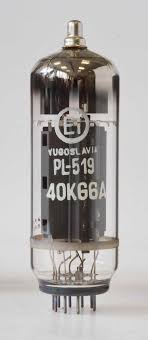
problem. This led me to the choice of 2x 4x PL519 in push-pull, a rugged
colour TV line output tube with low plate voltage and high plate
current. In this way I came down to a plate-to-plate resistance of about
1 kOhm at 600 V DC plate voltage, where you easily can build a ferrite
broad band output transformer down to 50 Ohms. A disadvantage of this
concept is that you have to give individual bias to each tube, that
means for the first start-up you have to align 8 potentiometers
carefully to nearly equal cathode currents for all the tubes. But
according to my experience this alignment remains stable over a long
time. I have inserted 1-Ohm-resistors in each cathode line and have
brought the voltage drops to 8 cinch connectors, where I can monitor the
DC component (with external filtering) as well as the real time current.
With 4 tubes in parallel per branch of course you have to take care for
self oscillations. The extensive use of bypass capacitors, ferrite beads
and parasitic chokes in the plate lines is mandatory as well as good
grounding concepts are. The tubes don´t pull control grid current (this
would even be true in class C!) but you need 3 or 4 W RF input power due
to all the ohmic loads at the tube´s control grids caused by the
individual bias paths. On the other hand this certainly helps to avoid
oscillations. You can see some pictures of this PA at https://www.qrz.com/db/DK1IS
By the way: why not to try these tubes at class D? With DC plate
voltages of perhaps 1200 V you should get a nice QRO-PA ...
Wolf, you are right: building such a PA from scratch is a time consuming
enterprise. I didn´t count the working hours but according to my lab log
the whole project took about 9 months - an adequate time for a new baby!
It was a great experience anyway.
Good luck and 73,
Tom, DK1IS
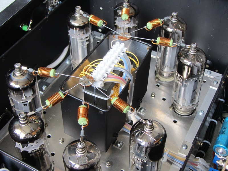 | ||
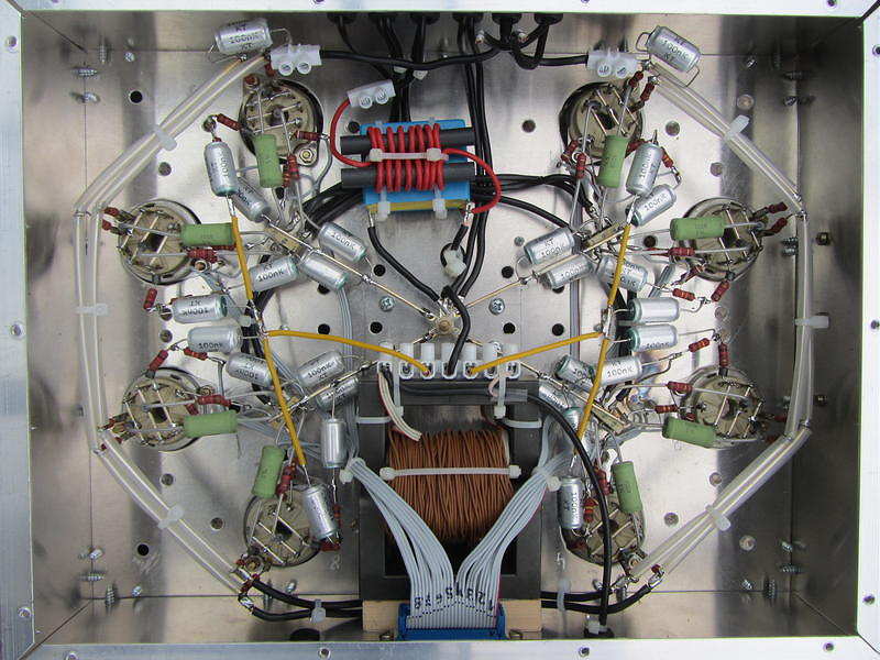
| 2x 4x PL519 Push-Pull |
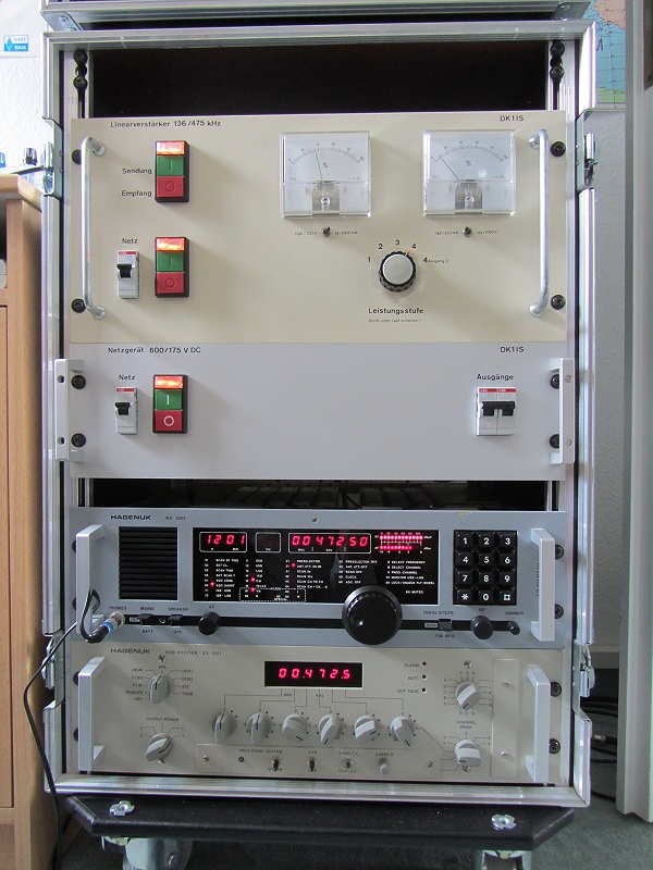 |
| TX, power supply, RX, exciter |
DK1IS has provided an inspiring example of what can be done using vacuum tubes ... they certainly should not be discounted as a viable method of generating your hard-earned LF / MF ERP.
The Artwork Of DK1IS
Recent discussion on the RSGB LF Group reflector about high-powered LF / MF amplifiers brought an interesting response from Tom, DK1IS, and his unique solution.
It's no secret that a Class D / E amplifier using switching MOSFETs is a popular and reasonably inexpensive method of generating some serious RF on the LF and MF bands. Equally well-known is their propensity to gobble-up FETs should the amplifiers encounter much reactance in their output load. Most builders include some form of protection for sudden over-current or unwanted SWR excursions which will shut down the amplifier before any FETs can self-destruct. Those that don't usually end up replacing FETs.
I would venture to guess that over 90% of the transmitters now being employed on LF or MF are using switching MOSFETs in a Class D / E design but there are some amateurs using vacuum tubes to do their heavy-lifting ... and with good results.
DK1IS's beautiful homebrew amplifier is shown below. Tom provided the following description:
Hi Wolf and group,
nice to hear that someone else is thinking about this approach! I´m
content with my homemade tube PA for LF and MF which has provided
reliable service since nearly 4 years now. Only some thoughts about this
concept - I hope not to bore all those hams who are happy with their
semiconductor PAs:
Years ago I had a MOSFET PA for LF, Class B push-pull with 250 W RF. It
worked well at constant conditions, but when I had to retune the antenna
due to larger QSY or made antenna experiments there always was the
danger of blowing up these nervous semiconductors. After 4 or 5 times
changing the MOSFETS I decided to build a new PA - with tubes! Looking a
little bit anachronistic this PA is absolutely good-natured. Designed for
broadband service on LF and MF it makes no problems when changing the
antenna coarse tuning from one band to the other even when the fine
tuning isn't done yet. With my former MOSFET-PA this would have been
impossible.
I wanted to have a linear PA - this usually means class B. You have to
decide between narrow band and broad band (like an audio-amp) design.
For narrow band you can use a single-ended PA but you have to add a
resonance circuit. For broad band you should use a push-pull PA and have
to build a suitable output transformer. I opted for broad band design
because it is usable for LF and MF without changes at the PA. With this
design and sin-driving I reach a total harmonic distortion of about 5 %
at 700 W RF on a pure resistive dummy load. With the usual narrow,
narrow band antennas on LF and MF you don´t need additional filters!
Concerning the tubes: If you take the common TX tubes with plate
voltages of several kV all output circuits have rather high impedances,
that means large coils for the resonance circuits resp. large
transformer windings and very high voltages - potentially a construction
problem. This led me to the choice of 2x 4x PL519 in push-pull, a rugged
colour TV line output tube with low plate voltage and high plate
current. In this way I came down to a plate-to-plate resistance of about
1 kOhm at 600 V DC plate voltage, where you easily can build a ferrite
broad band output transformer down to 50 Ohms. A disadvantage of this
concept is that you have to give individual bias to each tube, that
means for the first start-up you have to align 8 potentiometers
carefully to nearly equal cathode currents for all the tubes. But
according to my experience this alignment remains stable over a long
time. I have inserted 1-Ohm-resistors in each cathode line and have
brought the voltage drops to 8 cinch connectors, where I can monitor the
DC component (with external filtering) as well as the real time current.
With 4 tubes in parallel per branch of course you have to take care for
self oscillations. The extensive use of bypass capacitors, ferrite beads
and parasitic chokes in the plate lines is mandatory as well as good
grounding concepts are. The tubes don´t pull control grid current (this
would even be true in class C!) but you need 3 or 4 W RF input power due
to all the ohmic loads at the tube´s control grids caused by the
individual bias paths. On the other hand this certainly helps to avoid
oscillations. You can see some pictures of this PA at https://www.qrz.com/db/DK1IS
By the way: why not to try these tubes at class D? With DC plate
voltages of perhaps 1200 V you should get a nice QRO-PA ...
Wolf, you are right: building such a PA from scratch is a time consuming
enterprise. I didn´t count the working hours but according to my lab log
the whole project took about 9 months - an adequate time for a new baby!
It was a great experience anyway.
Good luck and 73,
Tom, DK1IS
| ||
| 2x 4x PL519 Push-Pull |
|
| TX, power supply, RX, exciter |
DK1IS has provided an inspiring example of what can be done using vacuum tubes ... they certainly should not be discounted as a viable method of generating your hard-earned LF / MF ERP.


