Posts Tagged ‘LBR installation’
 Don’t play Ingress at Radio Observatories
A few weeks ago, the IPG got some curious email from some ABQ-ians asking if they could play Ingress at the VLA to capture some GPS-based portals. If you’ve never heard of Ingress, think of it as geocaching with a Virtual Reality spin. Check out their website here.
Ingress is played on smart devices, which require data connections to operate. These data connections are fine and dandy unless you’re at the world’s greatest radio observatory; here they aren’t so dandy.
RF-EMS
Below is a screencap of our RF-EMS (Radio Frequency-Environmental Monitoring System) which captured two WiFi access points (the darker blotches) from an RV containing a Verizon 4G hotspot and another router for something else.
 |
| Your VLA on WIFI |
In the last blog I described the 10′ dish for pinpointing RFI. We also have a (usually) 24/7 monitor that uses some pretty nifty antennas and preamps on a 50′ tower, sending it to an HP 70000 Spectrum Analyzer in a RF-shielded room from which we can record and upload plots like the one above, every day for the past 5+ years.
 |
| RF-EMS Tower and Bunker |
The biggest downfall is adequate locating of interfering transmitters. Currently, I’m designing a method which will allow the IPG to quickly and accurately pinpoint people with any kind of transmitter, be it a cell phone, hotspot, or vehicle keyfob (if we wanted to locate such things). My idea is based on multilateriation, which uses multiple receivers around the site which compare arrival times to calculate a four dimensional location. Keeping the bill of materials as low as possible, simplicity, ease-of-use and network integration (without causing RFI itself) a prime focus.
It may be overkill, but it gives me something to do in the free time.
Other Doin’s: Testing out and Debugging the 74 MHz System
When I’m not having free time, this is what I’m doing. A new feature of the Expanded-VLA is observations on the 4 meter band. The current system in place uses these simple crossed dipoles hoisted a few meters below the sub-reflector.
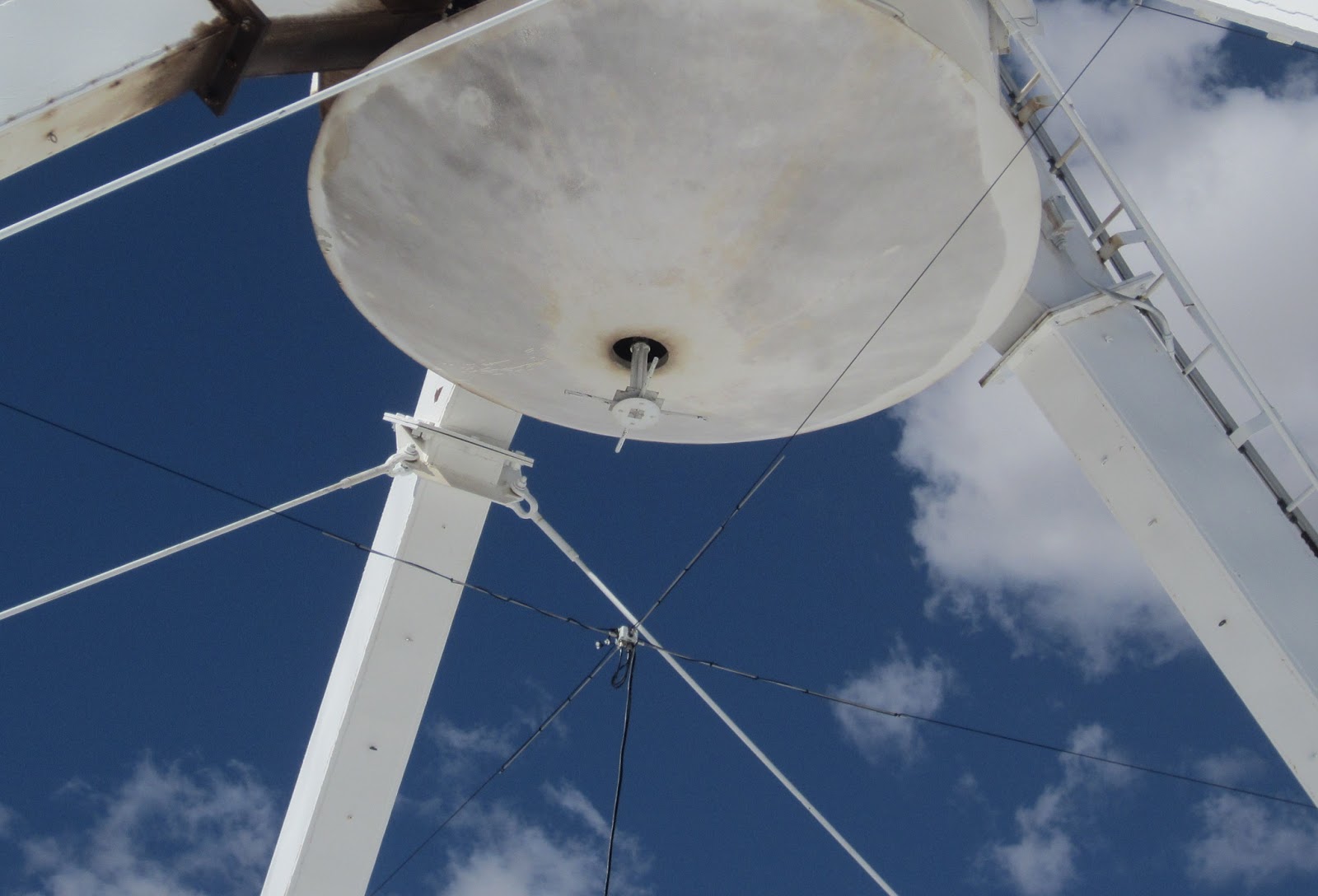
The cross dipoles connect to our receiver, which hooks up to the rack that magically digitizes the signal and turns it into pulses of light which the correlator feeds upon.
One of the problems we face are things broken that don’t have to do with our antennas and receivers. For example, the first test we do to examine the receivers performance is a band pass plot. Often times, we see something like this:
 |
| A bad bandpass plot caused by a faulty relay in the T301. |
This is ugly! What we want to see is this:
 |
| A beautiful bandpass! You can see 4 band on the left, and P-band in the middle with RFI spikes all over. |
First we go digging in the LO-IF and FE racks for a place to stick a spectrum analyzer to…
|
| Eric the BAMF next to the LOIF and FE rack. Our culprit is on the left, in the middle of the top rack of modules |

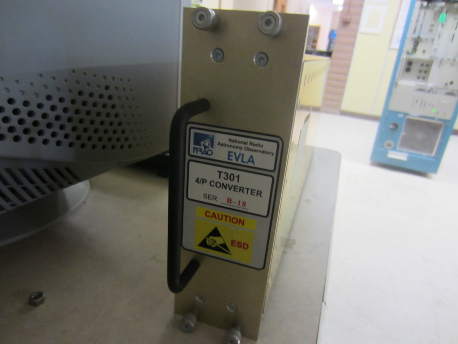
And from that we figure its’ this T301 which does the first IF up-conversion from 0-1GHz to 1-2GHz.
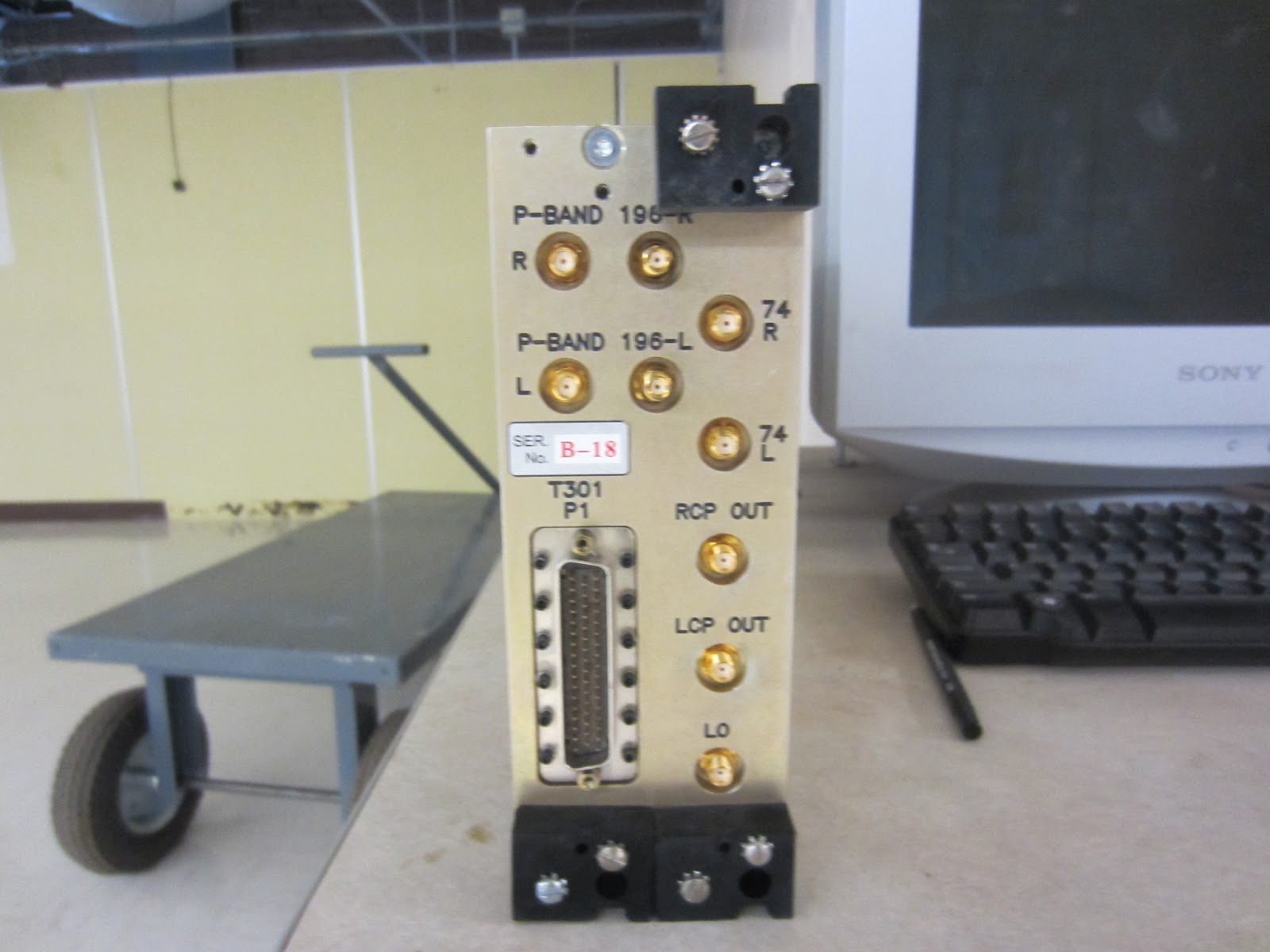
We get a new one, stick it in, turn it on and voila, it’s alive!
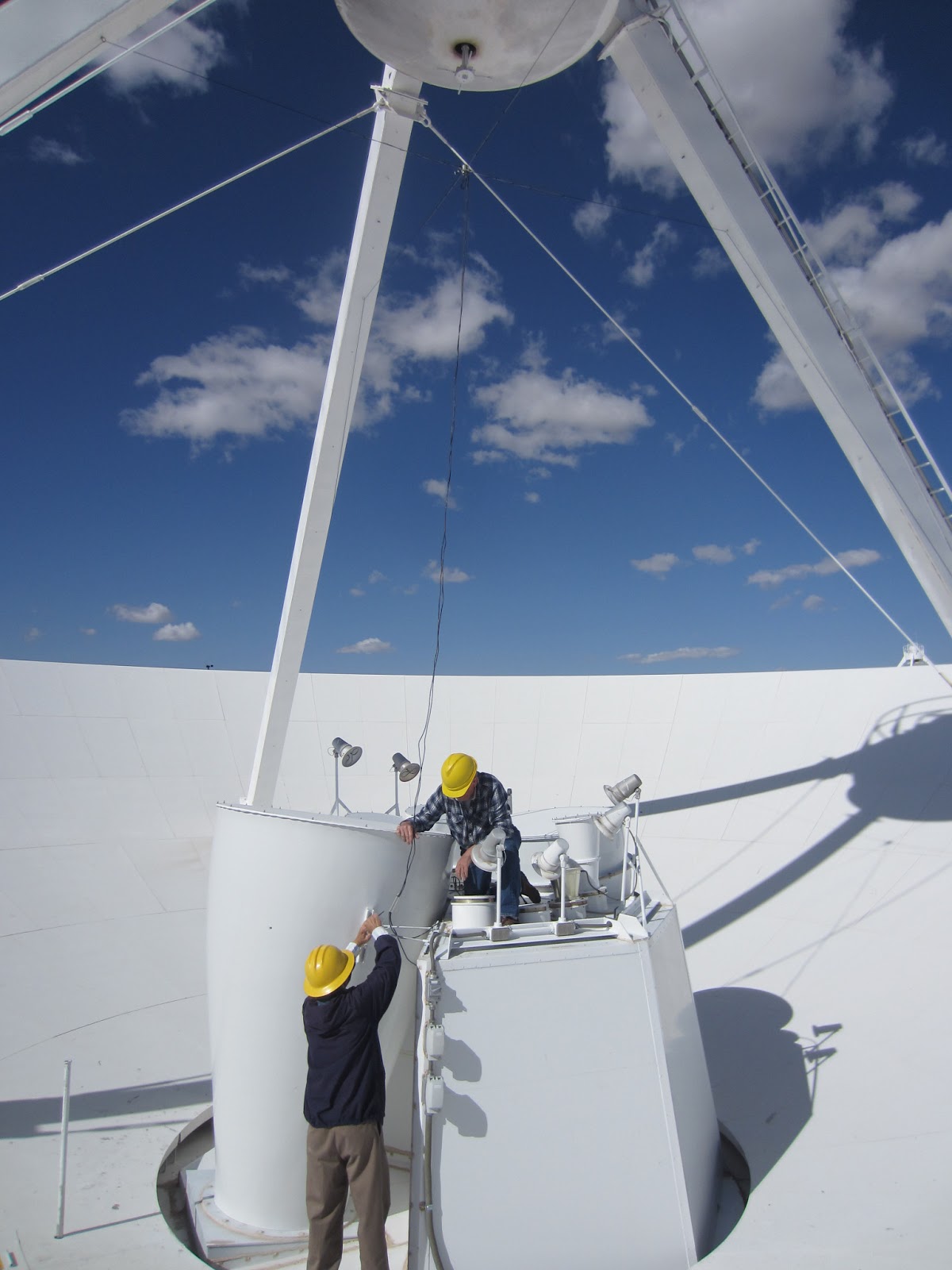
(A)Typical LBR installation
Like I mentioned, today Paul Harden, da boss, and I installed two more low-band receivers today, but with only a 50% success rate.
The receiver is dual banded for 74MHz/350MHz and is housed in a big and heavy 8″x12″ metal box. for thermal stability. We call them LBRs or 4/P receivers — 4 band is 58-80MHz (eg 4 meter wavelength) and P-band is 325-420 MHz or so. P comes from it’s old military designation, like L, S, C, X, Ka, K, Ku, radar bands, etc.
She’s mounted on a sturdy mount inside the “barrel” also known as the Focus Rotation Module, or simply the apex. It’s also my second home. Inside the barrel is a central square steel through which the 4-band antenna and receiver output cables go through. The receiver mounts near the bottom of the apex, and plugs in to 8 different cables – two pairs of Heliax for the 4/p band crossed dipoles, one Heliax pair for the output, a power cable, and a calibration signal cable.
Each antenna input requires two pair because of the dipole design — they’re orthogonal crossed dipoles that are fed into the receiver as two linear polarizations. Some magic happens in the LO-IF rack that either sends them as a linear polarization to the correlator (mainly for ionospheric observations) or combines them in quadrature to provide left- and right-circular polarization for observations outside our own solar system.
The first installation went smoothly — we removed a malfunctioning receiver from antenna 18 and replaced it with a fresh one — it’s pretty much plug and play. Somewhere through, we lost a two-way radio. No idea where it went. I think it always existed in some kind of quantum state, and now it’s hiding.
The second was troublesome. Each output, left and right polarization (or X and Y) should show clearly the band passes of each band through a spectrum analyzer. What we saw was spikes caused by the 74MHz *something* oscillating like a runaway Hartley. (that was a pretty poor play on words)
So we hit it a few times, jiggled the cables, and poof, it was back to normal! We came back down to the vertex room to find it again went nuts. So we went back up, wiggled some more, and took the SA with us. Now the X side was gone! We took the cover off and poked around, but it was dead. Methinks the oscillation was strong enough to saturate an LNA, bust a cap or diode or two, and kill X.
Paul’s gonna play with it tomorrow, and we’ll see if we can make our pseudo-deadline of getting everything working by Tuesday night. Lots of pressure from the higher ups.
Tonight, I’mma gon’ write a blurb about the SDR demonstration at the ARRL Youth Lounge at Dayton for Ward Silver, N0AX, upvote and argue things on reddit, and buy some wire and ladder line for field day. Need to make a 9:1 balun by then too.
 |
| View of South baldy and the Magdalena Ridge from the bus ride home |


