Posts Tagged ‘buildathon’
 CW decoder – The electronics

CW decoder – The electronics
CW decoder – Introduction
 If you do follow me on twitter (and if you don’t – you really should) you will have no doubt seen my recent tweets about constructing a CW decoder. After a number of retweets, and favorites from other very interested hams – I did promise that I would collate all my knowledge into a blog posts and share the details with you all.
So, for those who have not been following me on twitter – here is the sales pitch. I recently started looking at some projects that I could get my Arduino Uno involved in with the radio hobby. I have a number of reasons why I want to combine radio, Arduino and some electronics – more about this later.
I stumbled across a video on YouTube where Budd Churchward showed his Arduino copying and decoding CW straight off the HF band and at a reasonably high speed. I ventured further and wanted to know what electronics Budd was using to achieve this excellent little project.
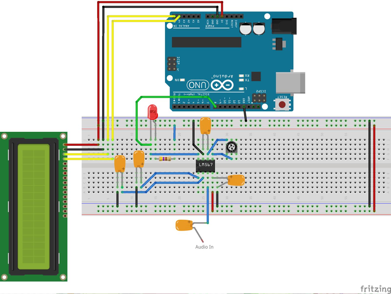
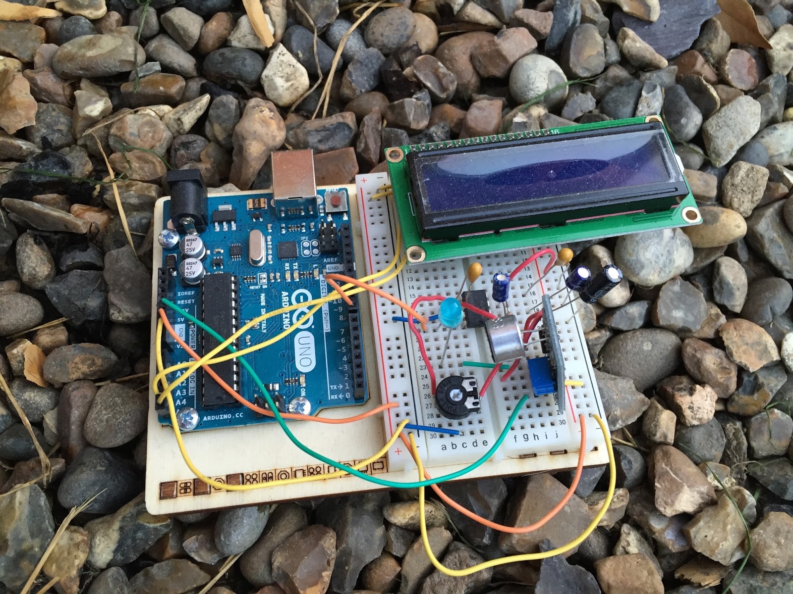
I used the limited shared knowledge and discovered that the electronics is basally a LM567 – Tone decoder chip that (I have since discovered the chip is used in the ARRL book for Arduino Projects) I discovered takes an audio input and converts this to a HIGH / LOW output suitable for the Arduino to use as a signal for decoding.
Finding a suitable project for the LM567 and trying to work out how fellow constructors had configured their LM567s was not an easy task. This did indeed take quite a lot of chasing and head scratching. I will go into more technical detail on the next post – but for the reason why I wanted to complete this ? very simple. I w
ant to create a project that would “inspire” young electronically minded students that might have an interest in radio – (i.e the morse code) some coding experience and some construction / electronic interest. This project covers all 3 areas, and only lightly covers each subject area.
In the next post – I show the LM567, the schematic and give you the list of parts required.
CW decoder – Introduction
If you do follow me on twitter (and if you don’t – you really should) you will have no doubt seen my recent tweets about constructing a CW decoder. After a number of retweets, and favorites from other very interested hams – I did promise that I would collate all my knowledge into a blog posts and share the details with you all.
So, for those who have not been following me on twitter – here is the sales pitch. I recently started looking at some projects that I could get my Arduino Uno involved in with the radio hobby. I have a number of reasons why I want to combine radio, Arduino and some electronics – more about this later.
I stumbled across a video on YouTube where Budd Churchward showed his Arduino copying and decoding CW straight off the HF band and at a reasonably high speed. I ventured further and wanted to know what electronics Budd was using to achieve this excellent little project.
I used the limited shared knowledge and discovered that the electronics is basally a LM567 – Tone decoder chip that (I have since discovered the chip is used in the ARRL book for Arduino Projects) I discovered takes an audio input and converts this to a HIGH / LOW output suitable for the Arduino to use as a signal for decoding.
Finding a suitable project for the LM567 and trying to work out how fellow constructors had configured their LM567s was not an easy task. This did indeed take quite a lot of chasing and head scratching. I will go into more technical detail on the next post – but for the reason why I wanted to complete this ? very simple. I w
ant to create a project that would “inspire” young electronically minded students that might have an interest in radio – (i.e the morse code) some coding experience and some construction / electronic interest. This project covers all 3 areas, and only lightly covers each subject area.
In the next post – I show the LM567, the schematic and give you the list of parts required.
Intermediate is go

We have started another intermediate class both in class and distance learning. This course is primarily run on Edmodo. We have run a couple of classes on Edmodo and we think we have the concept correct now. So we have our weekly quizzes set and our 3 week homework assignments all loaded and ready to go.
In class students are also welcomed to join the distance learning students so missing a lesson is no longer such an issue.
Over the coming weeks I will be creating some companion videos showcasing the practical elements of our in lesson activities.
So far we have 5 in class and around 30 distance learning joining us for the next 10 weeks.
Foxx 3 TRX build
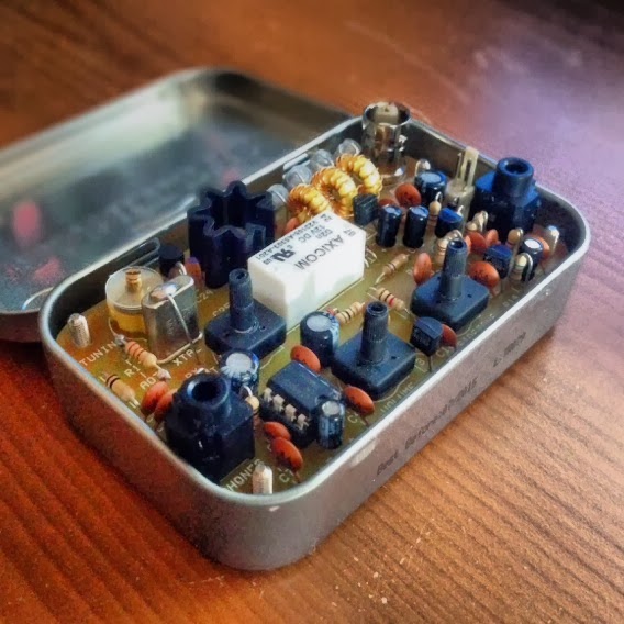 So it was my birthday recently and to celebrate the turning of another year and that I had indeed taken a day off – I decided to build a FOXX 3 QRP CW transceiver. These little kits are available from Kanga-products.co.uk and are designed to fit in a Altoids tin.
The kit comes pre bagged up in separate bags, and its just a case of soldering the correct component to the correct area on the circuit board. The kit itself is a 1 Watt QRP transceiver that can be bought on various bands. Mine was for the 20m band.
The board has a clear and easy to read Silkscreen and the pads are suitably wide enough to allow anyone with different levels of skill to create the kit. Each step allows you to test each part of the board, so you learn how each part of the kit relates to the transceiver as a whole.
I had a great time building it, it’s a simple, easy and great fun little kit. I hope to take it out and about – so hopefully you can hear my tiny signal on 20m soon.


