Posts Tagged ‘antenna lab’
 Antenna Lab
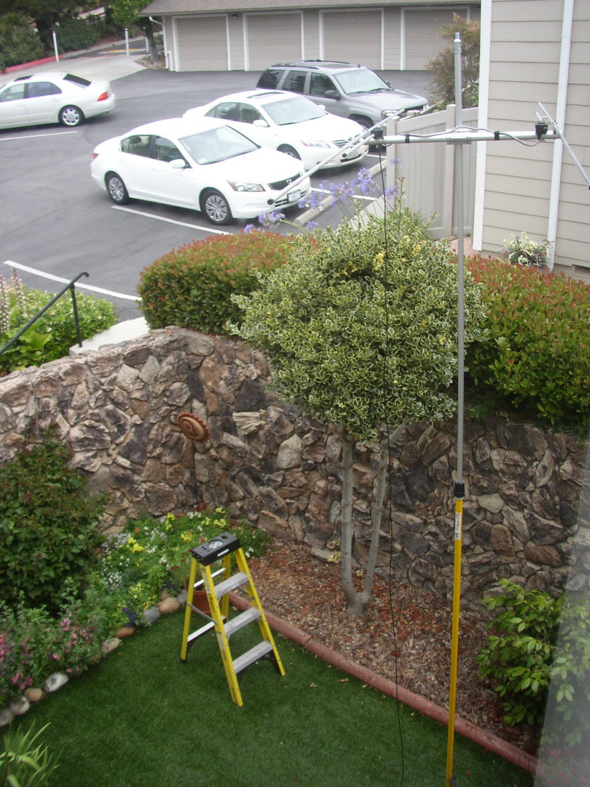 Photograph 1 taken from our second floor window.
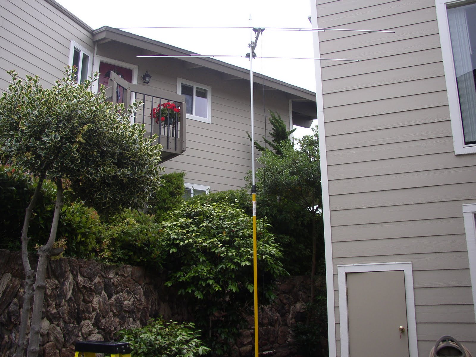 Photograph 2 is a street level few of the 6m 2 element yagi positioned in a difficult operating location.
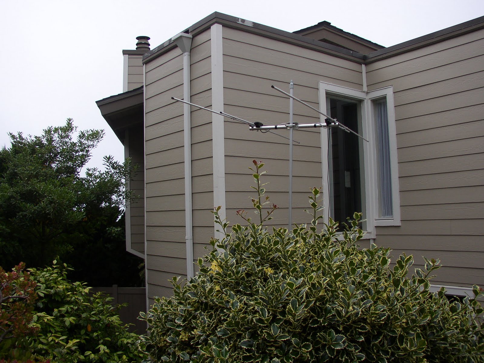 Photograph 3 taken a few steps upward from street level view.
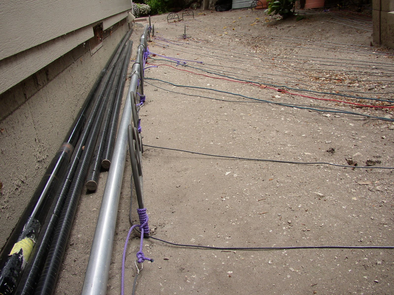
 Photograph 4 highlights additional radials installed yesterday afternoon. The total is thirty across three bands of operation.
 Photograph 5 illustrates the cement like quality of our soil just two hundred yards from the Pacific.
 Photograph 6 is an example of re-purposed, decorative lawn fencing.
73 from the busy shack relaxation zone.
K6MM’s 160m No Excuses Vertical
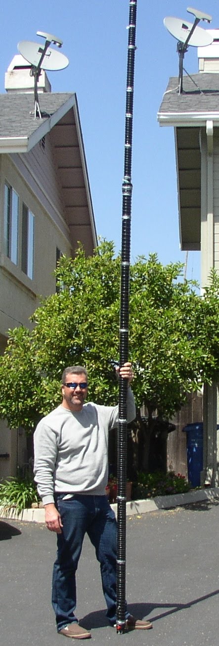 Photograph One illustrates completion of vertical section(s) one and two. I worked my lower back while winding but I’m confident the helical wind itself met my exacting standards. Duct tape used to secure every twelfth or so winding. My plan is glue the helical wind after field testing and final standing wave measurements are taken.
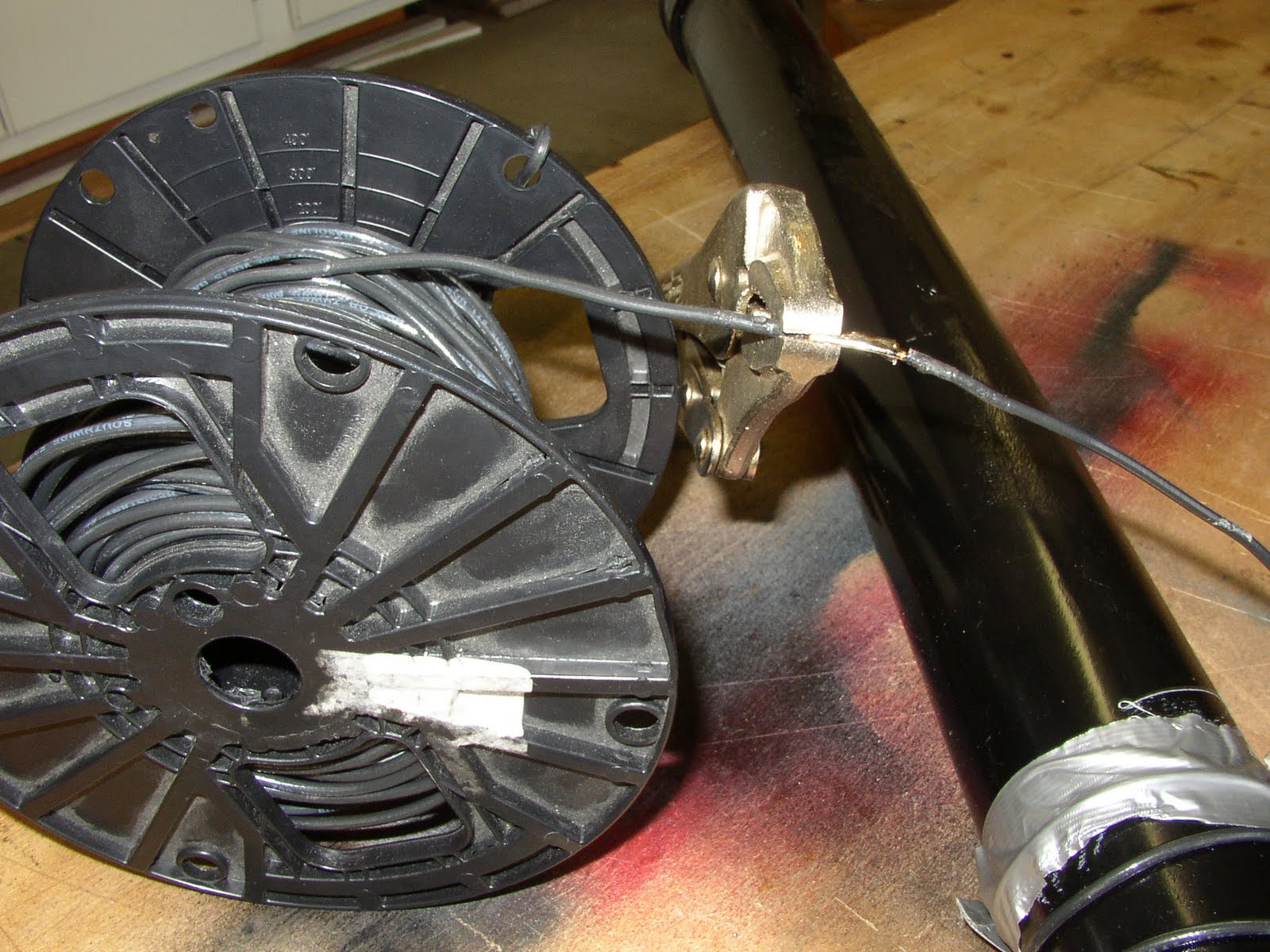 Photograph two taken of third man or a pair of vice grips used to secure first section wire splice. We discussed the wire splice illustration in the ARRL’s Antenna Handbook and concluded its six inch requirement with twist is best for dipole-like tensions. I scraped enamel coating from each AWG #14 solid core wire prior to soldering.
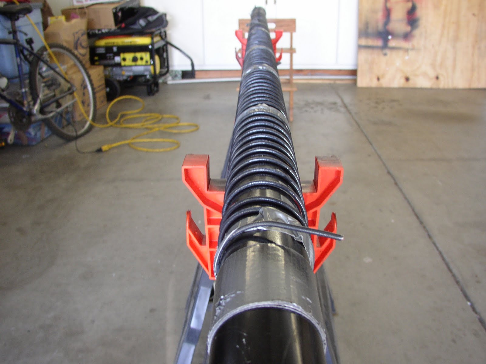 Photograph three depicts section one and two layout after completion of winding using a spool as illustrated in photograph two. The spool facilitated downward and upward motion creating enough necessary tension to wind antenna wire.
 Photograph four captures approximate 1/2 inch winds thus far consuming 201 feet of copper wire between first and second sections.
 Photograph five taken of a pair of slugs used to connect both sections. I opted for this type of connection as mechanically sound versus alligator clips given the potential for lateral motion. I’m constructing the antenna as a portable type rather than fixed. However I might be corrected on connection terms because I simply forgot after leaving the hardware store.
Remaining Project Objectives.
Section one is 45 percent complete and we’re fast approaching capacitance hat construction in the near future. Likewise, we’re discussing type of feed line for example, coaxial or window line as suggested in K6MM’s instructions. Furthermore, I’m brainstorming how-to fit 1/4 wave radials into the lot in the backyard, any suggestions?
73 from the shack relaxation zone.
P.S. Read K3LR’s method of installing a PL259 connector with photographs (link).
K6MM’s No Excuses 160m Vertical Antenna
 Photograph 1 depicts our first attempt at helically winding 97 feet 1 inch of AWG#14 wire on 2 inch PVC SCH40 before re-thinking our strategy. I opted for removing the long screw driver on the wire spool and approached our problem like taping a piece of pipe. I maintained upward and downward tension using the spool.
 Photograph 2 facilitated third person in this operation because handling a 10-foot piece of PVC is difficult to balance while winding.
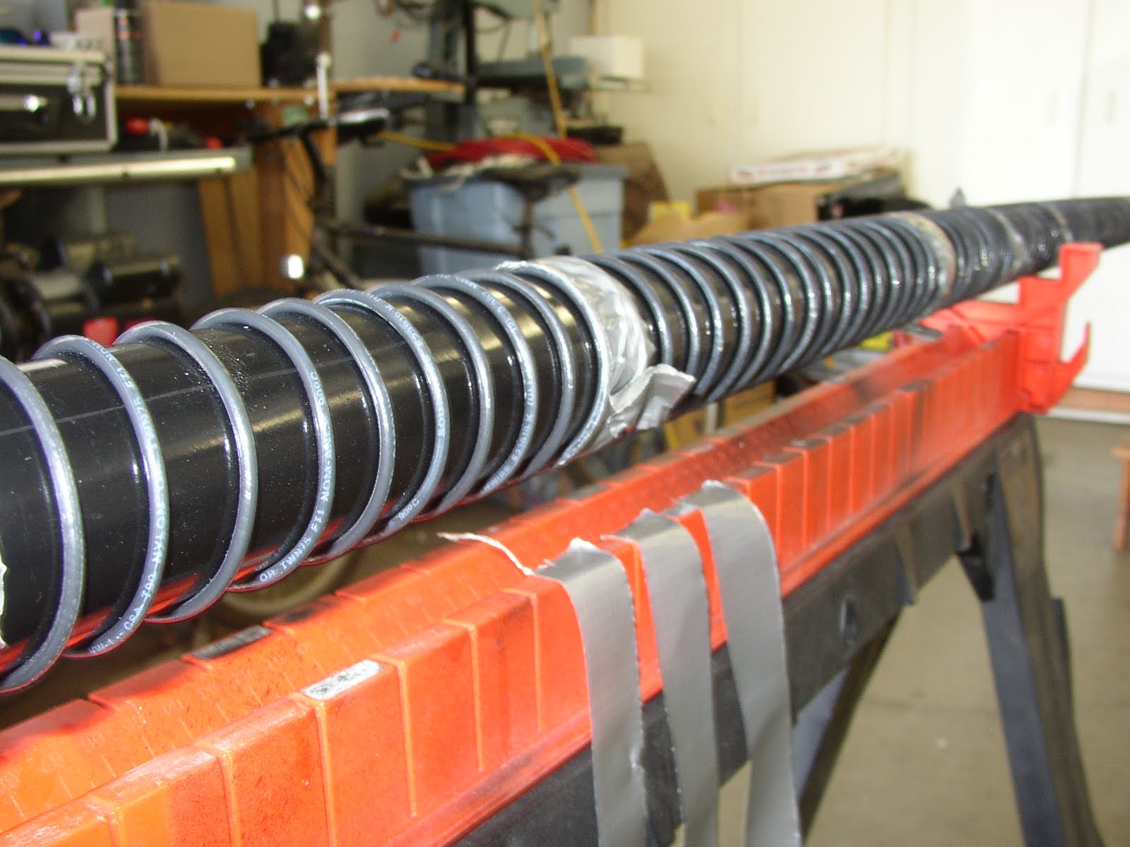
 Photograph 3 demonstrates our solution in addition eight inch lengths of halved duct tape at every 12th or so wind. We found taping at this interval suitable enough to maintain adequate tension. I attempted, to the best of my ability, half inch spacing between winds however I’m not satisfied with the quality of my work. Therefore, the next step in our project, includes adjusting each wind accordingly.
 Photograph 4 illustrates the end result of three hours of labor. My plan is to replace the spade located at the binding post while spacing each wind according to K6MM’s instructions. We divided each each section by the total length that is 256 feet 5 inches of wire equaling an average of 85 feet per section. Additionally, I’m purchasing alligator clips for each section because I’m intending to deploy the antenna in the portable mode.
Believe in your signal!
Shell Beach CM95 And 144 MHz Tape Measure Beam


 Fred, KI6QDH loaned his 144MHz Tape Measure Beam for field testing here in Shell Beach this afternoon. My location is ideal for pushing antenna performance issues at near zero feet above sea level to include geography conundrums. I found maintaining line-of-sight with our local repeater was problematic. Additionally, we shifted our frequency to simplex 145.500 and Fred’s signal was full quiet however he did not hear my transmission.
I experimented with an 1/8th vertical and the 3-element beam neither antenna produced dissimilar results. Both, in fact, performed poorly between .05 mW and 5-watts into our local repeater. The next antenna adventure at 144 MHz while walking Radio Dawg includes operating in the direction of Avila Beach beaming south of Shell Beach.
Project instructions are available from W6AB, Satellite Amateur Radio Club as a download portable document file.
73 from the shackadelic on the beach.


