Posts Tagged ‘amateurradio.com’
 The Road Home and Other Ham Radio Novels

On p. 32 of the March, 2012 edition of QST that came out this week, I am pleased to see a review of The Road Home, a novel written by Andrew Baze, AB8L. Coincidentally my son and I just finished reading this book, and we thoroughly enjoyed it. Despite a few typos and minor grammatical errors (specifically, the use of the indicative mood where the subjunctive mood should have been used), it is very well written. The plot is plausible and captivating. Mr. Baze makes ham radio (2m FM and APRS) an integral part of the story, and he makes it work — it doesn’t seem at all as though he were straining to slip it in somehow. Furthermore he displays a high degree of competence in operating procedures, emergency preparedness, and even defensive tactics.
While this book is light reading, there is still some character development of the young man who is the main character of the story. Refreshingly, the boy’s father is his guide (rather than being marginalized or vilified as parents often are in teenage fiction). Not only does Mr. Baze inspire a young person to get a ham radio license, he succeeds in developing the moral imagination of his readers. The Road Home cultivates an affection for such admirable qualities as diligence, perseverance, courage, level-headedness, familial love, compassion, and a chivalric desire to avoid violence yet defend women from evil with deadly force when necessary.
You can read this book for free, if you have a Kindle and an Amazon Prime account, by borrowing it from the Kindle Owners’ Lending Library for Amazon Prime Members.
 Other novels that my children and I have enjoyed are those written by Cynthia Wall, KA7ITT: Night Signals, Hostage in the Woods, Firewatch!, Easy Target, Disappearing Act, and A Spark to the Past. These six books are a series chronicling the adventures of fictional characters Kim Stafford, KA7SJP, and her boyfriend Marc, KA7ITR. They are definitely aimed at children, but if you’re like me you’ll still read them — it’s so hard to find novels incorporating ham radio that you just can’t pass these up.
Another novel that incorporates ham radio is Cornbread Road, by Jeff Davis, KE9V. Mr. Davis released it as an audio-book in a series of podcasts in 2010-2011, and my wife and I enjoyed listening to it together. The podcast is not currently available but hopefully it will be back up soon. Cornbread Road is aimed at adults. The main character is a ham who gets involved with a secret society of ham radio operators led by a mysterious figure with a past, a ham who is an inventive genius and who is himself caught up in a web of international intrigue. While the plot may tax your ability to suspend disbelief, it is still an amusing story and throws in a little of everything in ham radio.
Do you have any ham radio novels to recommend? I dimly recall one or two that I nearly wore out as a child (back in the days when I would ride my bicycle to the local library and read my favorite books over and over), but I couldn’t tell you much about them now. If you know of any — and where to find them — please chime in with a comment!


![]()
Online Course: Introduction to Emergency Communication
As a pastor the months of December-January are the busiest of the year for me, so I haven’t done much with Ham Radio for weeks now. That is as it should be. As I’ve said before, we must keep our hobby in its proper place. But I haven’t let it completely die, and the hopper has slowly been filling up with things to share with you.
 One of those things is the ARRL’s online/mentored course, “Introduction to Emergency Communication.” I’ve registered for the next session of this course which begins on February 29 and runs through April 27. It cost me $50 as an ARRL member ($85 for non-members), but I think it’s worth the money in my situation.
Not that I have to go through this course to learn the material. Much of the material may well be common-sense or a review of what I already know after being a ham for so long. The rest I could pick up by simply reading this book or (probably better) this book. Or I could glean it all from the web or learn it from an experienced member of ARES. So why would it be worth $50 for me to go through a formal course of study?
The answer: for credibility with governmental agencies.
Like it or not, to gain respect from governmental agencies you need to prove that you’ve jumped through a few hoops — especially in a state like Minnesota. Several decades ago Minnesota figured out how important it is to train police officers well. As a former police trainer myself, I cringe when I see poorly-trained officers on COPS. Trust me — agencies that have invested in training are rarely interested in “help” from poorly-trained people, no matter how well intentioned.
So before we go to the local sheriff (who is in charge of emergency management for our county) and talk to him about ARES, we need to get our ducks in a row. Training is #1 — and to governmental workers, that means certification of some kind. Be ready to show Show them paperwork. Other things help too, like uniform vests, jackets, etc., but those things come second. (In fact, you can shoot yourself  in the foot with that stuff if you aren’t careful. Take it from me — as a former police officer I know what I’m talking about — if you overdo “the look” in your uniform, your amber light bars, etc. most cops will write you off as a wanna-be commando kid to be kept far away from the grown-ups. If you really want to impress them, wear a tie. Seriously!)
Furthermore, for certification to mean anything to governmental workers it needs to come from the biggest, most widely recognized institutions you can find. For ARES, that means FEMA and the ARRL. I know some hams don’t like the ARRL, and I may get pelted with comments about how terrible the ARRL is. But there it stands.
In order to register for this course you must first complete two free online courses offered by FEMA: IS-100.b, “Introduction to the Incident Command System (ICS 100)” and IS-700.A, “National Incident Management System (NIMS), An Introduction”. Whether or not you take ARRL’s course, you really ought to take these courses (especially the first one) if you ever want to participate in emergency services. I for one needed to brush-up on these things, and I appreciated how well they were done.
Once you successfully complete these online courses from FEMA (they don’t take long) you may register for the ARRL course on the ARRL website. Registration closes on Wednesday, February 15 for the session I’m enrolled in, and on Wednesday, March 15 for the session that begins on March 28. There is still plenty of room in my session — of the 30 seats available, only 21 have been taken as I write this on February 4.


![]()
Pop’s Shed and the Kingsley Radio AR7
After my grandfather passed away I spent a lot of time recalling the good times I had spent scrounging around his CB shack and hanging out with Pop “down the shed”. If you’ve spent time around old motorbikes, retired lawn mower engines, vacuum tube electronics and inches of dust you know what the shed smelt like and probably have a pretty good idea what it looked like as well. I used to be able to send Mum into fits by embedding a combination of oil, grease, dust and grinding compound into the knees and sleeves of my good clothes after spending the day “over south” (South Geelong)
Even now I can still walk into any old auto mechanics and the smell brings back dozens of memories as clear as day … but one memory in particular had been bugging me for a while now. On several occasions I had used a magnificent rack mounted shortwave receiver that had been hooked to a long-wire antenna between the shed and the house. It had several plug in coils housed in bright metal boxes, one for each band as well as a unique tuning dial that had windows around the circumference with numbers that updated as the dial was turned.
 |
| National HRO right? … Nope, its an Australian clone! |
For the longest time I was thinking what you are probably thinking now, I had been using a National HRO receiver right? Well, you’d be wrong … just as I had been for years! When I eventually asked my uncle about the receiver (I waited a long time as I feared it had been thrown out & honestly didn’t want to know if it had) he said, “The AR7?” … “Yes, its here in the garage covered in dust”. He went on to say that I could have the receiver if I could figure out some way to ship it … not a slight problem given the receiver, power supply and speaker are over 120 lbs!
Knowing now that I had been using a completely different receiver I set to work and found out what I could about this National HRO clone …
From : http://www.vk2bv.org/
The AR7 was produced during WW2 by Kingsley Radio of Melbourne for the R.A.A.F. These receivers were used in ground stations for long range communication over fixed circuits as well as for receiving signals from aircraft.
The AR7 was based largely on the National (USA) HRO model, a fact that did not go unnoticed by National. This was the subject of litigation during the war years. Over 3000 of these receivers were produced and for their time, produced excellent performance.
These sets were very popular with radio amateurs after the war and unfortunately subject to many modifications. The Wireless Institute of Australia station, VK2WI at Dural New South Wales was equipped with modifed AR7’s for many years. I seem to remember that very local operators could block the receivers completely, resulting in hurried phone calls!
An unmodified AR7 is a rare beast. The Department of Civil Aviation used these sets for many years in a highly modified form, requiring a new front panel. Refinements included squelch and crystal locked coil boxes.
From : http://www.shlrc.mq.edu.au/~robinson/museum/AR7/
The AR7 is a communications receiver covering LF and HF bands. It was made in Australia during 1940 and bears an extremely close resemblance to the National HRO receiver. The receiver has a tuning range from 138 kcs to 25 mcs, with a gap of 45 kcs either side of the 455 kcs IF amplifier. The internal design is a single conversion superheterodyne receiver with 2 RF stages, 2 IF stages, a BFO and an “S” meter amplifier. The sensitivity is quoted as 1 microvolt. The front panel is stainless steel and it is a very distinctive looking receiver.
It is a good performer, sensitive, has a nice feel, is easy to tune, but hard to find the correct frequency, by reading the frequency from the dial number and coil box graph. It really needs a crystal calibrator. I use it for the weekly W.I.A. (Wireless Institute of Australia) broadcast, so it gets turned on once a week, and is so stable, than I don’t have to retune. It is very clear for AM but a bit fiddly for SSB.
The controls are: RF gain, BFO note, AVC/BFO switch, Adjust “S” meter, Tone, Tuning, Noise limiter, Selectivity, Crystal IN/OUT switch, Crystal Phasing, Audio gain. The Audio gain control has an OFF position which removes the HT so that the coil boxes can be changed.

It has two 6U7G RF stages, a 6K8G mixer, two 6U7G IF stages at 455 kcs, a 6G8G detector/AVC/audio preamplifier, and a 6V6G audio output amplifier. It has a 6C8G twin triode as a BFO and “S” meter amplifier. It also has a crystal filter. The IF alignment should be done very carefully, as any misalignment will reduce the effectiveness of the filter. It is best done with a sweep generator. The 6 volt valve heaters are connected in series, for 12 volt operation.
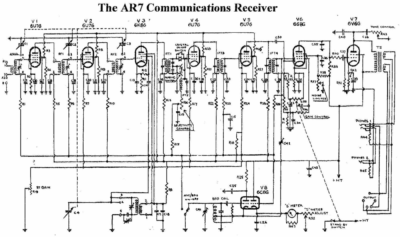
The external power supply and speaker, are usually mounted in a short 19″ rack, the AR7 at the bottom, the speaker in the middle, and the power supply at the top. The complete unit weighs about 118 pounds. The power supply was switchable between 12v and 240v.
The receiver was used as a ground monitoring receiver for aircraft. It was extremely stable. The model shown has an R.A.A.F. nameplate, and serial number 1786. The manual I have is a D.C.A. (Department of Civil Aviation) version and is a 1947 issue.
It has 5 plug in coil boxes. The coil boxes are: band A 140-405 kcs, band B 490-1430 kcs, band C 1.420-4.3 mcs, band D 4.25-12.5 mcs, band E 12.5-25 mcs. The Army version had an extra coil box covering 50-150 kcs. The large dial is a 20:1 reduction drive and has graduations from 0 to 500. It acts like a flywheel when tuning across the band, and has an effective scale length of 12 feet. The dial shaft goes into a right angle reduction gearbox and has 2 output shafts that drive 2 dual gang capacitors. The graph on the front of each coil box is used to covert the dial reading to frequency.

Hellschreiber and microprocessors – Bridging more than 80 years
ZL1HIT (Bryan Rentoul) has bridged a gap of more than 80 years by combining the text transmission system developed by Rudolf Hell in the late 1920’s with current microprocessor technology.
| A sample of received Hellschreiber test from Bryan’s beacon |
Hellschreiber sends a line of text as a series of vertical columns. Each column is broken down vertically into a series of pixels, normally using a 7 by 7 pixel grid to represent characters. The data for a line is then sent as a series of on-off signals to the receiver, using a variety of formats depending on the medium, but normally at a rate of 112.5 baud.
This process was historically accomplished with mechanical equipment but there are very few examples of this equipment still in operation and it is now sent and received by computer. Hellschreiber is very tolerant of noise and interference and requires only simple transmitters and receivers to work effectively.
 |
| German Hellschreiber unit in operation |
With a microprocessor generating the digital on-off signals a simple crystal oscillator transmitter can be used to form a beacon station, one that transmits a call sign and perhaps some other information over and over. Changing the transmitted message is as simple as reprogramming the microprocessor or having it respond to a connected input, for Eg. A thermometer, light sensor, switch, etc.
Receiving the signal and decoding requires a radio receiver capable of CW reception and a computer running any of several free software packages like FLdigi or Digital Master 780.
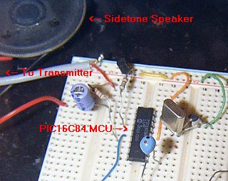 |
| The ZL1HIT beacon using a PIC microprocessor and a simple crystal oscillator transmitter. |
For more information and the PIC microprocessor source code please visit the web page of Bryan Rentoul here : ZL1HIT Hellschreiber / PIC Beacon
Anniversary of Vail’s First Demonstration of the Telegraph
Over at “This Day in History,” the lead story today is “Morse demonstrates telegraph.” It leads off, “On this day in 1838, Samuel Morse’s telegraph system is demonstrated for the first time at the Speedwell Iron Works in Morristown, New Jersey.” Well, I thought, surely this is worthy of a blog post, so I poked around on the web to learn more.
 It turns out that this first demonstration was put on by Morse’s partner, Alfred Vail. Vail had first become involved three months earlier when visiting his alma mater, the University of the City of New York. He stumbled upon Samuel Morse demonstrating his “electro-magnetic telegraph” with over one-third of a mile of wire coiled around a room. Vail was hooked. He convinced his brother George and father Stephen to support further development of the telegraph at the Speedwell Iron Works, and he signed an agreement with Morse to turn Morse’s crude prototype into a market-ready model — at his own expense — by January 1, 1838, in return for a minor share.
The challenge was to get the thing to work with a length of wire much longer than Morse had managed to use. Alfred Vail recruited an apprentice at Speedwell, William Baxter, and got to work. After many frustrations, they finally succeeded in getting their model to work:
At last on January 6, 1838, the machine was ready to be demonstrated. The cotton-covered hat wire was coiled around the room on nails to equal a distance of two miles. Alfred sent Baxter to “invite Father to come down and see the ‘Telegraph’ machine work,” which sent the eager lad plunging into the cold afternoon without stopping to throw a coat over his shop clothes.
The machine that sent Stephen’s message, “A patient waiter is no loser,” was still far from perfect. A few days later [January 11] several hundred men and women crowded into Speedwell to witness the first public demonstration. The message this time had a practical cast: “Railroad cars just arrived, 345 passengers.”
I’m not sure how these messages were formatted, but most likely they were not sent letter-by-letter. In those early days messages were laboriously sent using numbers that were assigned to commonly-used words. Eventually the “Morse Code” alphabet would replace this system, though great debate rages over who invented it.
Vail himself gives credit to Morse for the alphabetical system on p. 30 of his book, The American electro magnetic telegraph: with the reports of Congress, and a description of all telegraphs known, employing electricity or galvanism (available online for free), though some doubt the truth of this statement. Many years after his death, someone even sneaked in and engraved on Vail’s tombstone, “INVENTOR OF THE TELEGRAPHIC DOT AND DASH ALPHABET.”
Whoever invented the alphabet, what does seem clear is that Vail was the one who invented the straight key, an elegant improvement upon the cumbersome machines first used to encode messages. Today, you can even purchase a replica of Vail’s “spring key” from Kent Morse Keys!
Alfred Vail became increasingly frustrated by Samuel Morse’s lack of involvement in the development of the telegraph while publicly taking all the credit. Vail stuck with it for ten years before finally leaving the telegraph behind.


![]()
Minimum-Loss Matching Pad
In my last post I promised to write about the minimum-loss matching pad that I’m using to couple my signal generator to the device I’m testing. The source impedance of the generator is 600 ohms and the output is intended to be terminated in a 600 ohm load, but the device I’m testing is only 228 ohms. The way to match this with the lowest loss is with a transformer, but it is inconvenient and unnecessary to come up with a transformer for every mismatch this piece of test-equipment will face.
Thanks to advice from the ham who is guiding me in this project, I’m using a minimum-loss matching pad, also known as an “L-pad,” to match these two impedances. (I’d tell you who this fine fellow is, but to keep you in suspense about my project I’ll wait until my final write-up. If I name him now, the cat will be out of the bag!) This quick, cheap, and easy match requires only two resistors:

Courtesy of http://www.microwaves101.com/encyclopedia/attenuatorL-pad.cfm#minloss
To calculate the value of the resistors and to calculate the loss of the matching pad, use these formulas (A spreadsheet that uses these formulas is available through this webpage.):

In my case R1=472, R2=290, and the loss is -9.25 dB. That loss is pretty significant, but it is acceptable for this application. Remember this is a minimum-loss matching pad, not a no-loss matching pad. Using what resistors I had on hand to come as close as I could to the required values, I soldered this pad on a generic PC board from Radio Shack that I cut in half using my Dremel tool with a cutting wheel:


For more on this topic, I commend to you this webpage on “Impedance and Impedance Matching.”


![]()
1Hz-2MHz Function Generator Kit
 After building the “Accurate LC Meter Kit” from Electronics-DIY.com, I turned to their “1Hz – 2MHz XR2206 Function Generator Kit”. All parts necessary to complete the kit were included, though not exactly as pictured on their webpage — two of the WIMA capacitors had been replaced with substitutes and there was no IC socket. All components were through-hole; soldering the kit together went quickly and easily.
If you build one of these kits you’ll need to provide your own power source as well as your own pin-connectors (if you choose to use the pins provided). As with the LC Meter, I used a size M coaxial DC power jack to accept a plug from one of the wall-wart power supplies I have around here. I didn’t bother to install a power switch in either unit since I won’t be using them very often; I won’t leave them plugged in between uses.
The fellow at the local Radio Shack gave me some pin-connectors for free, clipping them off of some battery packs that were in a box for recycling, though he only had two-pin connectors. Since one of the pin-sets has three pins, I just soldered a piece of hookup-wire to the third pin. If I had to do it all over again, I wouldn’t bother with these pins — I’d just solder hookup wire right to the PCB. By the way, if you ever try soldering to a pin make sure you clip a heat-sink to the pin before heating it up. The plastic base of those pins melts pretty quickly!
I chose a plastic project box from Radio Shack to house this function generator. Using a Dremel tool with an engraving cutter (at the lowest speed — 5,000 RPM), I put three notches in one side of the box for the potentiometers, a notch on one end for the two switches, and ground down all four stanchions on the floor of the box since otherwise the potentiometers would have extended too high to allow the lid to fit. That Dremel tool sure is handy! A few knobs from Radio Shack finished off the project.
The two outboard switches allow you to select between three waveforms — sine, triangle, and square. I don’t have an oscilloscope so I can’t tell you how the waveforms look, but I can at least tell you that the sine wave sounded pure when I hooked my headphones up to the output with a matching pad. I am pleased to report that the signal generated by this function generator is very stable. Four DIP switches on the PCB allow you to select between four frequency-ranges, and two potentiometers allow you to tune within the selected range. One of these two potentiometers provides coarse tuning, and the other provides fine tuning. The third potentiometer controls the amplitude of the signal generated (note: amplitude decreases as you turn this potentiometer clockwise).
If you build this kit you’ll want to hook it up to a frequency counter. Two pads on the PCB are provided for this purpose. I have a piece of coax hanging out of the back of the box for connection to my own frequency counter — not that you have to use coax, but it was handy for terminating with a BNC connector. (If I were really classy I would have put this coax through its own hole in the project box, but hey, this is a piece of test equipment — I just ran it through the big hole I made for the RCA connector.) When I hooked up my frequency counter I noticed that the published ranges for each DIP switch were just rough approximations, but I was pleased to see that this frequency generator covered the entire published range and more — up to about 2.4 MHz, if I recall correctly.
Here is a slideshow of photographs I took of the completed function generator:
The source impedance of the generator is 600 ohms and the output is intended to be terminated in a 600-ohm load. In my next post, I hope to discuss the construction of a minimum-loss matching pad to hook it up to a piece of equipment that has a different input impedance.


![]()


