 |
 Regulated voltage for Regenerative receiver project
Mr. Regula-tor
Building a regenerative tube receiver seems to have been a rite of passage for all hams of yesteryear. Although I built one from a kit (4-States QRP) as my first electronics project a couple years ago I thought I'd go for the real deal and build a vacuum tube regen receiver.
I'm building a design based around the 6SN7 tube. While I'm collecting parts and still locating a suitable chassis I decided to build a regulated power supply from the parts I have. Anyone familiar with electronics could probably whip this together in no time, but being the electronics newbie that I am, it is a slow process.
I'm using a transformer from a 1950's Heathkit VTVM V-7 that I parted out. It supplies the 6.3V filament voltage from one set of windings (yellow wires) those tested good. But the HV was an unknown as it was only half wave rectified when the transformer was used in the meter. That meter's rectifier and power cap had gone bad so I didn't know what condition the HV side of the transformer.
Breadboarded using a full wave rectifier created with 4 diodes, buffered by a 22uF electrolytic and a 10k resistor, I saw 189 volts, with no-load out of the high voltage side of the transformer. The amount of current the transformer could provide was still an unknown. I tested temporarily with a 2.5kOhm high wattage resistor and saw 56ma of current provided with a voltage sag down to 130V but the core of the transistor started heating up. Within half an hour it was over 120F so I discontinued that load test.
Fortunately, the regen circuit uses a ridiculously small amount of current for B+; about 4 to 5mA. Although I will likely change the audio side of the tube to deliver enough current for a speaker rather than the high impedance headphones in the current design, which may potentially double that to 10ma. For the first incarnation I'll stick with high-impedance headphones.
Fortunately, the regen circuit uses a ridiculously small amount of current for B+; about 4 to 5mA. Although I will likely change the audio side of the tube to deliver enough current for a speaker rather than the high impedance headphones in the current design, which may potentially double that to 10ma. For the first incarnation I'll stick with high-impedance headphones.
The regen power supply requirements called for [email protected] and 90V@4mA B+. The B+ voltage was based on using 10x 9V batteries and it stated that voltage wasn't critical but shouldn't fall much below 90V, going 12% above 90V should be OK.
Generally batteries are used with regenerative receivers because they are so sensitive to power supply noise, but I wanted to give the power supply a shot first and if it proves too noisy I can fall back to battery power for the B+ and just use the filament voltage provided by this transformer.
Since I have a OB2 voltage regulation tube I want to use. The OB2 regulates at 108V so that's what I'm going with. An OB3 would regulate at 90V, but I don't have one of those.
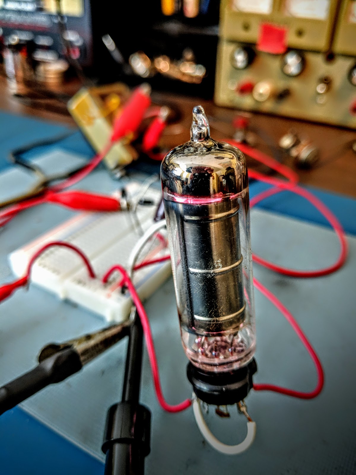 |
| OB2 in action... Glow baby, Glow! |
Calculating the resistor drop
A voltage regulating tube like a OB2 ionizes gas to maintain the voltage at the tube's specification. In the case of an OB2 it tries to maintain voltage at 108V. It requires a starting voltage higher than what it will regulate to, but ultimately can only dissipate so much current as it drops voltage. So, a resistor must be put in series ahead of the VR tube to limit the current it will have to dissipate. The resistor must be able to handle the current flowing through it, so that must be calculated as well.
The calculation for the dropping resistor resistance is:
Rdrop = (Vs - Vreg) / (Ireg + Isupply)So, in my case:
Voltage supply (Vs) = 189V
voltage regulation (Vreg) = 108V
regulator current (Ireg) the OB2 requires 5mA to do its job = 5mA
supply current (Isupply) the actual current required by the 6SN7 up to ~ 5mA
So, (189V - 108V) / (0.005A + 0.005A) comes out to a resistor value of 10,100 ohms. 10k is the closest standard size resistor and at 108V it should be able to dissipate 1.166 watts. So I'll need a 10k 2-watt resistor.
Parts is parts
Running the regulated power supply with a 10k Rdrop resistor for a few hours showed the transformer stabilize at 92F degrees at 70F amb. I was using a separate 27k 2-watt resistor to simulate the ~4mA load that the receiver will draw at 108V.
As you can see on the newly restored, trusty Heathkit VTVM; the voltage was holding steady around 108V. With that little current, the OB2 is not visibly glowing but with the lights out the violet colored ionization is visible.

Summary
I'm going to order a larger filter capacitor. The only one I had to test with was 22uF 360V and I'd like to use higher capacitance value of 47uF with a more appropriate voltage rating of 250V. I will also be adding 0.01uF caps at the input and output of the filter capacitor and I may add a 0.01uF across the OB2 pins 1/7 to further attenuate any RF noise.
With the current values I'm seeing 50mA ripple on my regulated voltage.
With the current values I'm seeing 50mA ripple on my regulated voltage.
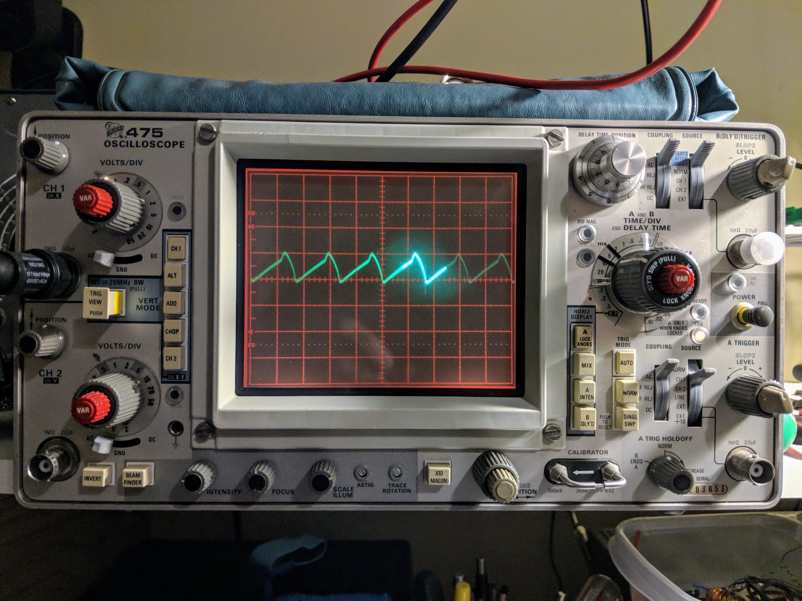 |
| A bit over 50mA ripple |
After I get the new capacitor and get the 0.01uF caps in play to filter out noise, I'll hook it up to the oscilloscope to check for ripple. I'll update the post at that time.
That's all for now....
So lower your power the old fashioned way, using a voltage regulator tube.
72/73
Richard, AA4OO
That's all for now....
So lower your power the old fashioned way, using a voltage regulator tube.
72/73
Richard, AA4OO
Please support our generous sponsors who make AmateurRadio.com possible:
 Ham Radio Deluxe |
 W5SWL Electronics |
 Ham Radio Prep |
 KB3IFH QSL Cards  Hip Ham Shirts  HamRadioAuctions HamRadioAuctions Reliance Antennas Reliance Antennas Enigma Shop Enigma Shop |  morseDX  Ni4L Antennas  R&L Electronics R&L Electronics antennas.us antennas.us QRV QRV |
- Matt W1MST, Managing Editor
