 |
 Argent Data Radio Shield
I’m a bit of an Arduino fan. I’m also interested in APRS. So I was keen to get hold of something that would bring the two together. Enter the Argent Data Radio Shield
I bought one a while ago and used it to make my shack clock. Arduino’s come in a lot of shapes and sizes but the Uno is probably the simplest. You can add bits and bobs to them through stack-able ‘shields’. One of these shields is the Argent Data radio Shield. I ordered mine before going on holiday and got a bit done over on the customs charges but have assembled the little thing and put together one of the simple sketches to show the thing working.

All ready on the bench
All in all the assembly was pretty straightforward with a few parts to put together and not a lot else. You don’t get much in the way of guidance but the suppliers website has all the pertinent information and it shouldn’t challenge most who are ok with a soldering iron. As shown here as a finished article

Ta Daaaaa
Below is a little video clip of the thing running a simple sketch from the website. Instead of the output being to an LCD I’ve sent it to the Arduino IDE serial monitor. This is easily done by not actually putting an LCD on the headers. All nice and simple.
Alex Hill, G7KSE, is a regular contributor to AmateurRadio.com and writes from Cumbria, UK. Contact him at [email protected].
Win 500 Free Color QSL Cards

AmateurRadio.com is offering a free prize drawing!
With the help of our generous sponsor, KB3IFH QSL Cards,
we’re holding a giveaway for 500 free full-color photo QSL cards.
This is a US$75 value and open to all licensed hams worldwide.
Matt Thomas, W1MST, is the managing editor of AmateurRadio.com. Contact him at [email protected].
Emory Peak Activation
For those not familiar with the Summits on the Air (SOTA) program there are bonus points added for activating a summit either during the winter in cold climates or during the summer in hot climates. West Texas is definitely a hot climate. Emory Peak is a 10 point summit (maximum), but activating in the summer months is worth 3 extra bonus points. On the drive from Mt. Locke to the Big Bend area temperatures hovered between 99 F to 101 F. The temperatures would moderate a little at the Chisos basin where we were staying, although not a lot. The Chisos Mountain Lodge is around 5500 feet in elevation, but the high temperatures during this time of year are in the low 90's.
The Chisos Mountain range within Big Bend National Park is a beautiful place. Emory peak may be the only peak that is climbable, but even then, you must climb the last 35 feet using some, not so easy, rock climbing techniques. I would not recommend it if you aren't experienced.
The trail to the summit of Emory Peak is a very nice trail. It is well marked and maintained. The only issue is that the round trip is 9.4 miles and there is 2,500 feet of elevation gain. Given that distance the elevation gain is not particularly difficult, if you are accustomed to mountain hikes, but it is a long way.

 |
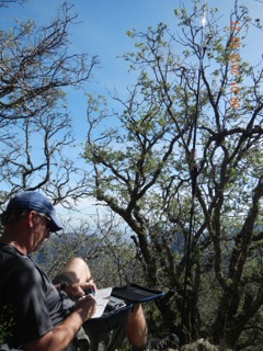
| Cris, my XYL, just below the summit |
 |
| AD5A just below the Summit VHF Antenna above are on the Summit |
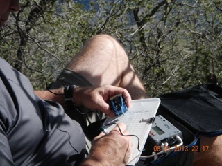
 |
| Emory Peak Shack You can see the Buddi-stick if you look closely |
Mike Crownover, AD5A, is a regular contributor to AmateurRadio.com and writes from Texas, USA. Contact him at [email protected].
A first QSO on the FO-29 satellite and some 50/70MHz Es
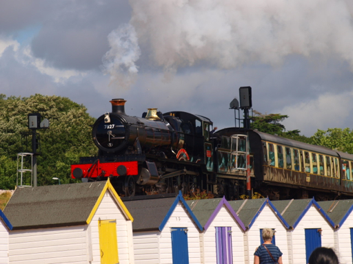
We’ve just returned from an excellent week’s holiday in South Devon. I took the picture at Goodrington Sands, which has the dual benefit of being a nice beach and having a steam railway behind it.
I took the FT817, whip antennas for 21, 50 and 144MHz as well as the Elk 144/432MHz log periodic. In the event, the only radio operating that really ‘called’ was satellite operation.
I listened on a few SO-50 passes, most of which were quite busy, but without managing to make any contacts.
However, I did take the plunge and try FO-29 for the first time. The lack of full duplex on the FT817 makes this a bit of a challenge, but thanks to some sage advice from Pete 2E0SQL on where to transmit and where to listen, I managed to work DG0ER for my first contact on this satellite. I heard some other interesting stations such as UA9CS as well, so must make an effort to feel a bit more competent on FO-29.
Back home today, after I’d finished writing the Practical Wireless column, I switched on and found 50 and 70MHz buzzing with Es. I was pleased to work IW9HII (JM67) on 70MHz for what must be my best DX on the band this summer at around 2000km as well as I3VWK. On 50MHz, I was pleased to work old pal T77C who was coming through nicely on CW.
Tim Kirby, G4VXE, is a regular contributor to AmateurRadio.com and writes from Oxfordshire, England. Contact him at [email protected].
K3 gets a hearing aid
There was a slight lift on 6m this afternoon, enabling me to try out my latest acquisition: an Elecraft PR6-10 preamp for the K3. A few days ago I noticed that the KX3 had a more sensitive receiver than the K3 on 6m. I couldn’t allow my K3 to be outshone by its baby brother so the preamp was ordered. I felt that the K3 could do with a boost on some of the lower bands as well so I opted for the new PR6-10 dual band preamp which despite the name covers the range from 6m to 12m. It was obtained and delivered to me very speedily by Elecraft’s UK agents Waters and Stanton. This was one Elecraft item that actually worked out cheaper to buy from the UK!

The preamp was very easy to install. It is designed to fit on the back of the K3 using the BNC connectors for RX IN and RX OUT provided by the KXV3A board. The preamp’s connectors are exactly the same distance apart as the ones on the K3 so you just need a pair of BNC couplers which Elecraft thoughtfully provided. I saw from the manual that the preamp was installed like this but I was afraid I would not have enough distance between the back of the K3 and the wall so I had ordered a couple of BNC patch leads as a precaution. In the end they weren’t needed.
Elecraft also provided a made-up cable to link the preamp to the K3’s switched 12V output and its ACC socket so you can select the bands the preamp is enabled for. On other bands a pair of pass-through connectors are enabled. This was the main factor for choosing the ready-made Elecraft preamp instead of a cheaper home-brew one as it meant I didn’t lose the use of the RX IN and RX OUT sockets that are utilized by the MFJ noise cancelling unit which is essential here on the 20m band.
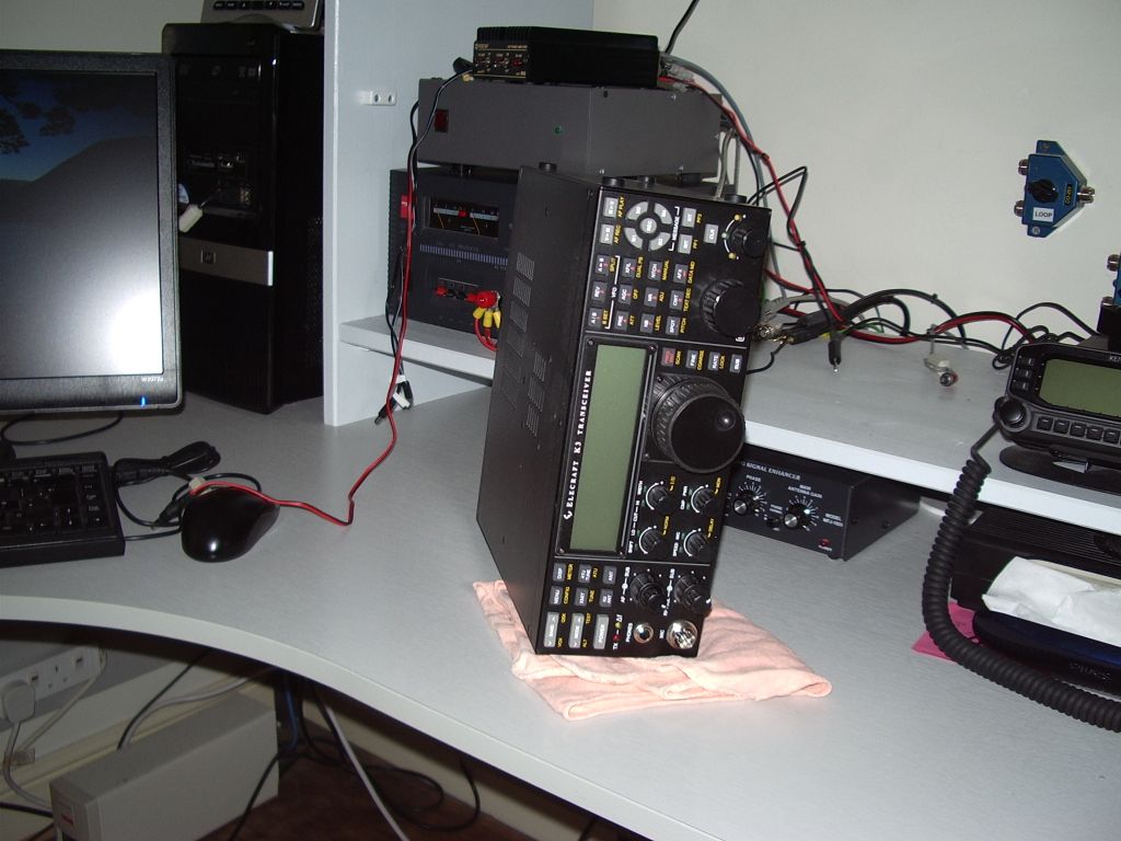 |
| Installing the preamp involved dismantling the entire station. |
Although fitting the preamp to the K3 was easy, getting access to the back of the transceiver was not, and entailed the dismantling of almost the entire G4ILO station. Taking it apart may have been one thing, but putting it all together again is another. Labels fell off disconnected cables, other cables disappeared down the back of the table and had to be fished out again. If that wasn’t enough, the meter illumination lamp in the MFJ magnetic loop control box chose this moment to fail, resulting in a lot of time wasted after I had reconnected it trying to find out what I had done with its power supply.
Despite these hassles, installing the PR6-10 was worth the trouble, producing a clearly audible improvement in signal to noise ratio even on 12m. I can now hear stations that can’t hear me!
Julian Moss, G4ILO, is a regular contributor to AmateurRadio.com and writes from Cumbria, England. Contact him at [email protected].
End of the holiday
After a good 7 months of work without much time off I’ve come back off a lovely holiday in Ile de Re, France. The island is 4km off the coast of La Rochelle and is a fantastic place and a popular place for ‘Le Weekend’. It reminded me how bad my French was but nice to practice what poor language skills I have.
Famous for salt and donkeys in pyjama’s as well as good wine and sea food. Gros Jonc is the long vertical beach on the right hand side at the top of the picture. Lovely in the sun and 2 minutes walk from where we were staying.

The closest I got to radio was seeing a chap with a TM25H (Le Mans 24 hour race special event station) T-shirt but as he was heading for the gents I wasn’t going to strike up a conversation.
Alex Hill, G7KSE, is a regular contributor to AmateurRadio.com and writes from Cumbria, UK. Contact him at [email protected].
I guess it works – but not the best design!
I had a little more trouble when I went to the Jeep on Friday for my lunchtime QRP session. I just wasn’t hearing anything! I know the bands can get that way, but the past few days had been relatively decent. Like any other Ham Radio operator, my mind immediately went to “There’s something wrong with the radio!”
As I disconnected the coax from the KX3, I noticed that the radio’s BNC post turned a little bit as I removed the coax fitting. I knew that by itself wasn’t the problem, but I didn’t like the fact that it was a tad loose. I broke out the tools and did some field surgery on my KX3 right in the back of the Jeep! I felt like Hawkeye Pierce, BJ Hunnicut or Trapper John from MASH. I opened the KX3, removed the auto tuner board, and with a pair of needle nose pliers, I snugged up the nut that holds the BNC post against the inside housing of the radio. Then I put everything back together and turned the radio back on ….. still nothing.
I just recently replaced the PL259, so I twiddled that around, thinking that perhaps I didn’t do as good an installation as I had thought. Nope, no difference – that wasn’t the problem either. So even though I had taken the magmount assembly apart the previous night, I decided to look again there – a mistake on my part there? Once again, all was good there. But I did notice that as I twirled the cable around, I was getting signals to appear, disappear and then re-appear. A break in the coax cable!
So I brought the magmount back in the house once again. I decided that I was going to take it apart, cut back about 8 inches of coax and then put it all back together. In the process of taking everything apart again, I just happened to pull on the center conductor of the cable and a six inch piece came out with my fingers. It had indeed broken, back in the main part of the cable, and my plan to cut it back by a foot and reassemble turned out to be a good plan.
But I have to tell you, after working on this, I’m not really impressed with the design of this magmount. I hope you can figure out what I’m trying to describe. The coax goes into a plastic housing. This plastic housing is roughly the diameter of a quarter and is maybe a 1/4 inch thick. Each half has a hole. The shield of the coax (which has been pigtailed) goes through the bottom hole, while the center conductor (which is kind of flimsy) goes through the upper hole. There are channels or depressions on each side for the wire to sit.
The is the order in which it all goes back together – from the bottom working towards the top.
1) Through bolt
2) Plastic insulator, so that the through bolt does not touch the magmount body (ground).
3) Magmount body
4) Coax housing with the braid sandwiched down, between the coax housing and the magmount body.
5) Metal washer. The center conductor lays in a channel and is pointing up, to be sandwiched between the coax housing and the washer.
5) Threaded hex sleeve for the radiator.
Everything is held in place by the holding pressure created by screwing the through bolt into the threaded hex sleeve! The center conductor is NOT soldered or otherwise electrically connected to the metal washer underneath the threaded hex sleeve, as I had previously thought. And as I noted before, the braid is simply sandwiched between the plastic coax sleeve and the magmount body. I made sure all metal surfaces were clean and shiny and used plenty of Deoxit to help ensure good electrical contact (there really are no true connections!) as best possible.
It seems to me that it would have been better for the coax to be soldered or otherwise connected to the metal sleeve and the magmount body other than just using physical contact and screw pressure to hold everything together. But then I suppose that would have increased the cost of the product significantly.
In the near future,I think I am going to upgrade the quality of the coax, too.
72 de Larry W2LJ
QRP – When you care to send the very least!
Larry Makoski, W2LJ, is a regular contributor to AmateurRadio.com and writes from New Jersey, USA. Contact him at [email protected].
 Ham Radio Deluxe |
 W5SWL Electronics |
 Ham Radio Prep |
 KB3IFH QSL Cards  Hip Ham Shirts  HamRadioAuctions HamRadioAuctions Reliance Antennas Reliance Antennas Enigma Shop Enigma Shop |  morseDX  Ni4L Antennas  R&L Electronics R&L Electronics antennas.us antennas.us QRV QRV |
- Matt W1MST, Managing Editor
