 |
 Mini Rotator?
Whilst leaning out of the car window and manually turning my decorators pole (complete with 70cms 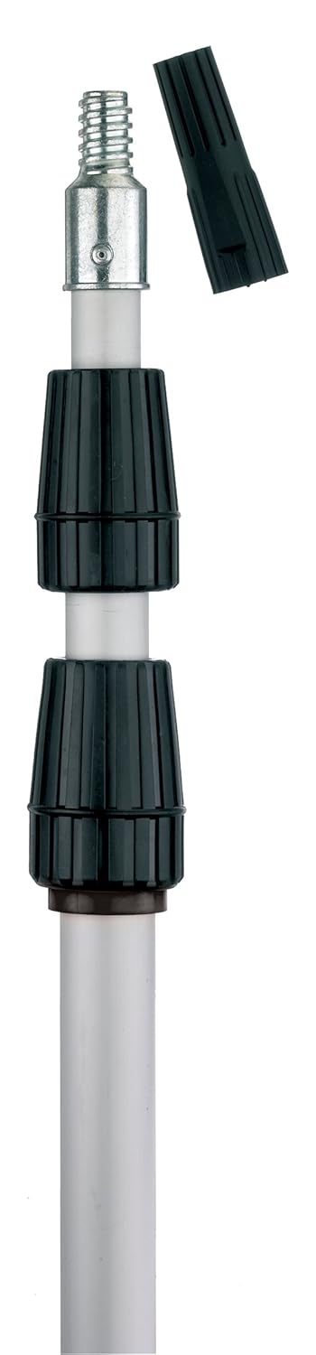 antenna) and waiting for a break in a UKAC (VHF Contest) QSO I thought that there must be a better way of doing this.
The antenna weights way less that 1Kg and the decorators pole has a perfect coarse thread to it so it shouldn’t be too hard to make up a simple attachment with a stepper motor on it, driven of course by the mighty Arduino and its motor shield
Although I’ve not put one of these together and its a bit of a pipe dream whilst work keeps sending me all over the place I’ve seen more that my fair share of articles that use the motor shield to drive stepper motors (guessing its some kind of H bridge / relay arrangement). So I’m guessing (again) that the bare bones of the system could be pulled together over winter. ready in time for next years UKAC series.
I enjoy the UKAC series but running /P has its unique problems up here in West Cumbria. As I type now the winds are getting stronger and we expect the gale force variety over the weekend. Even when we’re not being blasted with salty Irish Sea venturing out /P means that having a car window open in the winter on the top of a hill is ‘challenging’.
So the challenge is on me now to come up with something now that my work project is attempting to shift from ‘Madness’ to simply ‘Frenetic’ between now and November and possibly simply ‘Stressful’ in December.
Once that’s done…hah ha…I’ll concentrate on the single boom 6m / 2m /70cms antenna I’ve been thinking about that means I don’t have to crawl around in the dark with loads of bits in the car.
Still if someone’s done it already, please put me out of my suspense.
Alex Hill, G7KSE, is a regular contributor to AmateurRadio.com and writes from Cumbria, UK. Contact him at [email protected].
Lownely
It’s always nice to find that other people’s findings match your own. PA0RDT is famous for his design of the mini-whip, a very small but effective long- and medium wave antenna. Roelof found that the magnetic component of a radio wave could more easily go through obstacles, while the electrical component was more contained within a closed space, like a house. This means that the electrical component of noise generated by appliances in the house stays inside – mostly – while the magnetic part travels outside the walls. Thus his mini-whip design picks up the electrical component only and amplifies that. If the antenna is placed some distance from interfering obstacles it will result in a strong, but relatively noiseless signal. I build one and can say it really works.
But amplification comes at a price: IM and overload. Passive loop antennas have non of the afore mentioned problems. Since the beginning of my radio days I have always had a one metre square loop antenna for MW and LW and deep in my heart I longed for one. So I build one again, but this time bigger: 180 cm square with the corners clipped. Tuning is done remote with a BB112 varicap. The circuit was once published by the Benelux DX Club and I’ve had it for over 25 years, but never build it to this day.

Because of bad weather I could only put it up last weekend and boy, what was I disappointed. It seems it picks up all the television noise from the whole neighbourhood, with added noise from within my own house. The mini-whip is clearly better than the loop, so PA0RDT is right. But using another laptop power brick helped a bit and after firing up Argo it seemed that despite the noise the loop was still proving itself useful.
The loop tunes from 136 kHz to just above 400 kHz, which covers most of the NDB frequencies. Even though long wave beacons are on the decline there are still a lot of them. I heard some 30 new ones over the weekend, both in the daytime and at night. Argo is a great tool, sometimes beating my ears in picking up signals. Here some screen shots.
Locator “O” on 201 kHz and PQ on 202 kHz, both unidentified.

An odd one heard on 220 kHz: BRBA5. Notice that the dash in the letter “R” is longer than the other dashes. Ears won’t notice this, but with Argo you can see it.

Three beacons on the same frequency of 380 kHz: LM, OB and sandwiched in between YU from Hualien (Taiwan’s east coast).

NDBs are fun to DX, but my goal is to do some 2200m DX. Without any voltage applied to the varicap the loop is tuned to 136 kHz, which means I can leave it on all night and hope that I can detect some signals from Japanese hams, or maybe the Philippines. Unfortunately Chinese hams are not allowed to use 2200 meters and I don’t know of any Taiwanese hams operating this low. Help! I think I am becoming “low-nely.
Hans "Fong" van den Boogert, BX2ABT, is a regular contributor to AmateurRadio.com and writes from Taiwan. Contact him at [email protected].
The simplest possible AM transmitter
Here’s a design for a 1 MHz amplitude modulated (AM) transmitter. I’ve been looking a while for something like this, a simple short range AM transmitter for the medium wave band, as I needed something for demonstration of my collection of old radios.
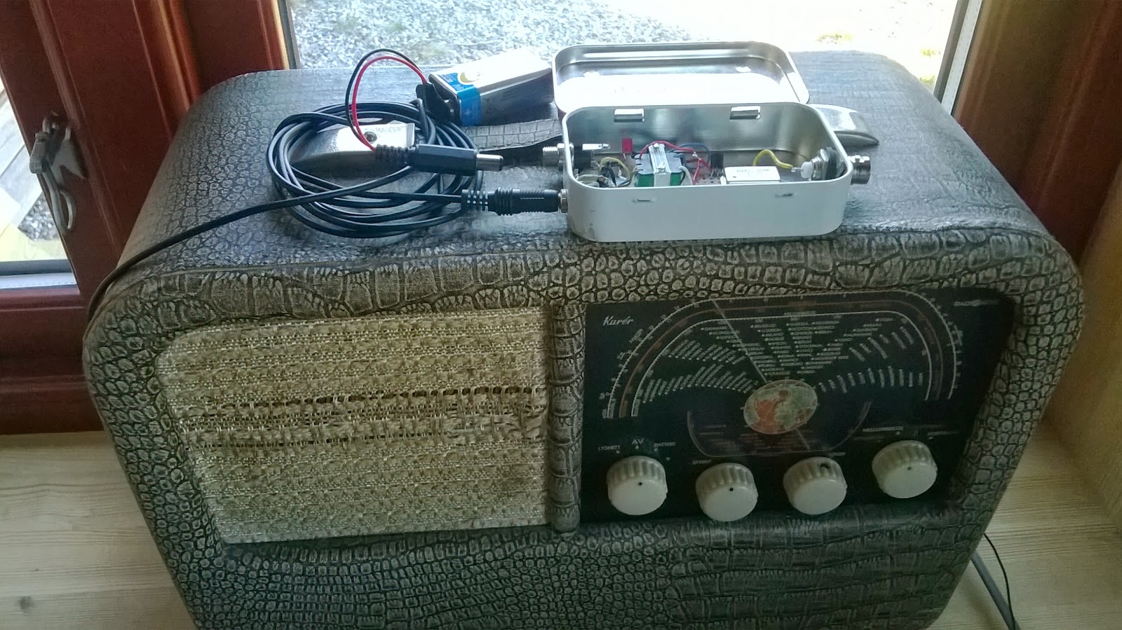
The result is the AM transmitter shown here in an Altoids tin on top of a Radionette Kurér radio. This is a portable tube radio from the 1950’s. Several hundred thousands were produced, and it was exported from Norway to 60 countries. It is still popular among collectors.
The transmitter is as simple as it gets. The heart of it is a 1 MHz crystal oscillator in a can. Its 5 Volt power is modulated via an audio transformer, one taken from the output of a transistor amplifier (primary 147 ohms – secondary 3 ohms). I drive the modulator from my cell phone into the low resistance side of the transformer and get good audio when the phone’s volume is set to maximum.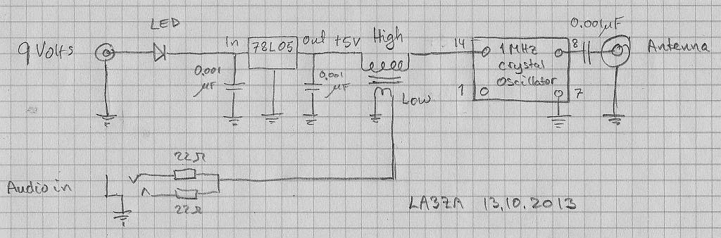
The design was inspired by one from Instructables, but mine also has a 78L05 5 Volt voltage regulator and a red LED in series with the power supply. It indicates that the battery is plugged in. In total the transmitter draws 4.4 mA at 9 Volts. The input power to the oscillator is less than 5 Volts * 4.4 mA or in the order of 20 mW. The power output is just a fraction of that. I have tested it with a 1.5 m wire hanging down behind the built-in frame antenna in the back of the radio with good results.
This is really just a modulated marker transmitter as I have briefly described on this blog before, and the square wave will have harmonics of 1 MHz over the entire short wave band. Some of these frequencies may propagate really well, so if used with a longer antenna, it should really have an output low pass filter to prevent that.
I’m not totally happy with this design, despite its simplicity, though. If I could, I would rather like to transmit in the long wave band at 216 kHz. This is the old frequency of the Oslo transmitter which ceased operation in 1995. As a member of the Norwegian Radio Historical Society, I am allowed to use that frequency with a transmitter input of 0.5 W for demonstration purposes.
For other frequencies, one simple alternative is a standard canned oscillator at 1.288 MHz. I also believe some of the Silicon Labs oscillators can be used in order to get an adjustable frequency, but I haven’t tried that myself.
But until I find a suitable frequency source at 216 kHz, I’ll stay with the 1 MHz alternative at a mere 20 mW. It is in line with the best principles of KISS (keep it simple stupid) or with Occam’s principle : “It is vain to do with more what can be done with less“, i.e. the QRP philosophy.
Sverre Holm, LA3ZA, is a regular contributor to AmateurRadio.com and writes from Norway. Contact him at [email protected].
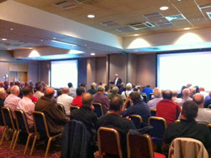
A day at the RSGB Convention 2013
You can never please all the people all of the time! We all know the truth of that statement. I thought the programme for this year’s RSGB convention was a particularly strong one. But talking to a friend at lunchtime, he felt it was a weak one! a couple of people mentioned the lack of any contesting content, other than the trophy presentations!
The best day for me to attend was Sunday, immediately meaning that I couldn’t see GW8JLY’s Meteor Scattter and YO4FNG’s VHF DX presentations, both of which I would have loved to have seen, but they were Saturday only.
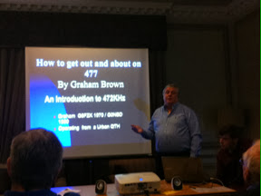
I arrived on Sunday morning and found my way to the room where Graham G0NBD was presenting on the 472khz band. Given my experiments I was interested to hear how it was being done ‘properly’. Graham’s presentation was fascinated and I came away with a few ideas. An interesting snippet was that apparently, in addition to the IC706 working on 472khz, so does the old IC735 – up to about 25 W of output!
There were also some interesting uses for the RTLSDR dongles and making them work much lower in frequency. I need to have a look at that!
I would have loved to have had more time to hear about propagation on the band, but Graham filled 45 minutes very easily and capably.
Next I headed over to hear half of the OFCOM update, presented by Paul Jarvis and Ash Gohil. I was impressed with what I saw and felt they did a good job, with a generally good natured, but challenging audience! There were some in the audience who seemed specialised in making issues where no issues existed! However, it was an interesting session and gave a flavour for the nature of the upcoming consultation on the amateur licence review.
Far from being faceless Government officials, which one might be tempted to imagine. Paul and Ash came across well, seeming very approachable and genuinely willing to listen.
After this, I was looking forward to Pete, 2E0SQL’s ‘Another slice of Pi’ presentation. At yesterday’s presentation, Eben Upton himself, from the Raspberry Pi Foundation was in the audience. No pressure, then! but Pete said they had a great and very fruitful conversation in the bar afterwards, with Eben offering some interesting insights to forthcoming developments.
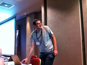
Pete’s presentation was excellent and I came away with some more things to try with my Pi – particularly with some ideas for new software to try.
I didn’t fancy the Roast Pork lunch so much, so drank coffee and chatted with friends, some not seen face to face in 10 years or so. Undercurrents of ‘politics’ are never far away and I noticed a couple of discussions going on which I was glad I didn’t need to be involved in!
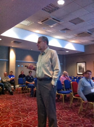
After lunch it was time for the presentation which had been the trigger for me to attend the convention, ‘DXing with weak signals’ by Joe K1JT. You may remember I have referred to Joe as one of my ‘Ham Radio Heroes’. I really wanted to hear him speak and if possible to meet him and have the chance to say ‘thank you’.
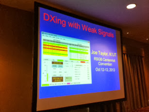
Joe was an excellent and engaging speaker. Although I know his software pretty well, there were some very interesting points discussed and things I learned.
I was particularly enthused about the idea of getting on 144MHz EME. Joe talked about having worked over 800 stations with his station which uses a pair of 10el X-Y yagis. This was inspiring!
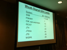
It was interesting to get a sense of how the various JT modes stack up with SSB, CW and so on – just how weak can a signal be to get some intelligence out of it.
I would have quite happily listened to Joe for hours, but sadly the talk was soon over, but it was a privilege to hear him speak.
A really enjoyable and inspiring day out!
Tim Kirby, G4VXE, is a regular contributor to AmateurRadio.com and writes from Oxfordshire, England. Contact him at [email protected].
A Short Journey Down History Lane: 1939 New Zealand Radio
Shortwave radio history – communications in and out of New Zealand in 1939. This history is rich with adventure and successes that are profound. Our modern communications all stems from this historic work…
This is a short film about the romance of the radiotelegraph service that utilized the high frequency spectrum known as “shortwave” (from 3 MHz up to 30 MHz) as well as the longwave and medium frequency spectrum (below 3 MHz). This is a short film about communication to and from New Zealand on these shortwaves, using Morse code (eventually, using CW modulation). This film is a 1939 Government film scanned to 2K from a 16mm combined B/W reduction print.
Visit, subscribe: NW7US Radio Communications and Propagation YouTube Channel
Mongolia
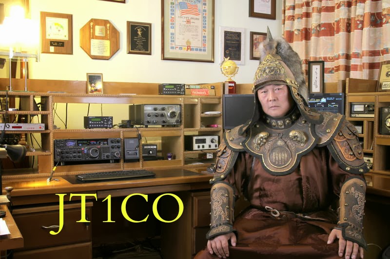
First, I did not work him, unfortunately. But I did hear him on 28038 KHz calling CQ. First I thought it was Japan, no alarm bells were ringing. But when I looked at qrz.com I saw it was Mongolia, so I fired up the rig for transmitting, but then his signal was gone. Yes, that happens on 10 meter band often.
I made a short documentary about a boy who knows a lot about mills. So I followed him with my camera and made this film. The mill is a watermill from 1896. Still on duty to keep our feet dry.
Now my set is tuned on 10m for WSPR.
Paul Stam, PC4T, is a regular contributor to AmateurRadio.com and writes from the Netherlands. Contact him at [email protected].
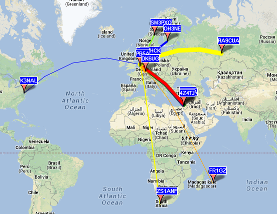
Always take a look at 10m

It's worthwhile to take a look at the 10 meter band. I did it today. First I worked UP5ØA with CW. Then I heard W3EP with 599 signals. Yes, I worked him and also W1VE with very loud signals.
Paul Stam, PC4T, is a regular contributor to AmateurRadio.com and writes from the Netherlands. Contact him at [email protected].
 Ham Radio Deluxe |
 W5SWL Electronics |
 Ham Radio Prep |
 KB3IFH QSL Cards  Hip Ham Shirts  HamRadioAuctions HamRadioAuctions Reliance Antennas Reliance Antennas Enigma Shop Enigma Shop |  morseDX  Ni4L Antennas  R&L Electronics R&L Electronics antennas.us antennas.us QRV QRV |
- Matt W1MST, Managing Editor
