 |
 Sun is still very active
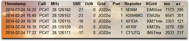
WSPR on 10 meter today with 1 watt output. Not much, but 2 reports across the pond. Tomorrow new HF black outs can be expected.
Paul Stam, PC4T, is a regular contributor to AmateurRadio.com and writes from the Netherlands. Contact him at [email protected].
Welcome new readers
I was very surprised, shocked even, to be asked to syndicate my postings to the site. Hopefully my posts will be of interest to a wider audience.
I have been a licensed amateur operator for six months currently on the bottom of the UK licence structure, the so called Foundation licence, but am hoping to take the Intermediate licence soon.
The main driving force for wanting to progress is I want to build things, to experiment and learn.
In a natural extension/diversion from my day job I have already been experimenting with the Arduino platform, initially with the intention of developing a High Altitude Balloon tracker but more recently with other radio related projects including a satellite tracker and using it in conjunction with DDS modules for WSPR/QRSS purposes. I have just built a dedicated Ultimate 3 QRSS kit from Hans Summers (G0UPL)
The DDS module are particularly interesting and I have some tentative plans for an Antenna Analyser and a Power/SWR meter capable of working down in the mW range which I stumbled across on the website of Loftur E. Jónasson - TF3LJ / VE2LJX. This is of particular interested to low power QRP operating. Did I mention that I have joined the GQRP Club?
Progressing from a couple of Baofeng VHF/UHF handhelds (which I hardly use) to a proper rig last month with the purchase of a Yaesu FT-857D I have been dipping my toe into the frightening world of operating!
It is common for new amateurs to be "Mike Shy" and I admit to suffering terribly. Not being the most outgoing or confident person being confronted by a barrage of rapid fire abbreviations, codes and etiquette it took a while before I had the courage to key up.
I plucked up the courage to have an attempt at some of the RSGB UKAC VHF evening contests and after gaining a bit of confidence I ventured properly onto the HF bands this weekend making a few simple signal report QSOs.
I should like to thank all those who have been patient with me as I fumble along.
Because of the shyness the use of data 'digital' modes is a strong draw since it uses computers and you don't have to talk! I am salvaged some suitable connectors to build a new computer data interface for the FT-857D, I built one several years ago but it got slightly cannibalised when experimenting with an ARPS gateway.
I can afford a commercial interface but why should I pay over the odds for something I can easily build myself? The desire to homebrew isn't just driven by cost, but lets be frank this can be an expensive hobby! Nothing gives more satisfaction when something you built works.. and yes they may be famous last words.
Andrew Garratt, MØNRD, is a regular contributor to AmateurRadio.com and writes from East Midlands, England. Contact him at [email protected].
Doing the MFJ loop happy dance!!
1. Tuning the loop for max noise (as low SWR was not happening) did happen but as soon as the rig was tuned in any way the noise dropped to nil.
2. Once max noise was achieved and I transmitted the max noise was gone again.
3. There was no spots on the Reverse Beacon Network while giving the tuned match a go.
4. When transmitting power levels were all over the place from 1 watt to 5 watts.
I had posted my 20m tuning problem on 2 loop user groups and had some great advice but nothing seemed to even come close to solving the problem. I then emailed MFJ who very promptly emailed me back and advised me to change the shape of a 12 gauge copper loop that was located inside the loop. Easier said than done this involved removing half the plastic cover on the loop and changing the shape of this loop then
 |
| Adjusting the loop |
 |
| Some plates to close |
Mike Weir, VE9KK, is a regular contributor to AmateurRadio.com and writes from New Brunswick, Canada. Contact him at [email protected].
TX Factor – new online ‘TV’ amateur show
I’m always a bit apprehensive when I hear there’s going to be a new amateur radio podcast. There have been some very good ones and some very bad ones! Just because someone is a keen radio amateur, doesn’t necessarily make them a good broadcaster on the subject!
The ‘TX Factor’ (corny name, but hey…) boded well. The presenters are all professional broadcasters. Bob, G0FGX is someone that I have come across on air a couple of times recently and he’s an engaging and interesting guy with plenty of broadcast experience. Mike G1IAR and Nick 2E0FGQ both have impressive CVs. Mike looks to have a particularly interesting job, mastering recording sessions for some big names.
I had a chance to catch up with the first TX Factor show yesterday. It’s well produced, engaging and inspires you to want to have a go. I really recommend you take a look.
I love Cornwall and it was interesting to see the Poldhu segment. I was glad to see that Bob addressed the question of whether Marconi’s ‘S’ signal really did get heard in Newfoundland! The SOTA activation was very nicely demonstrated by Tom M1EYP and it was good to see Mike G1IAR visit the Norman Lockyer Observatory in Devon. Great stuff.
Well done and I’m looking forward to seeing more shows. They must take quite a bit of production – well done to the team.
Find the TX Factor’s website here
Tim Kirby, G4VXE, is a regular contributor to AmateurRadio.com and writes from Oxfordshire, England. Contact him at [email protected].
Series Seven Episode Four – US Ham Survey (23 February 2014)
Series Seven Episode Four of the ICQ Amateur / Ham Radio Podcast has been released. The latest news, Martin (M1MRB) and Colin (M6BOY) discuss the an emergency box for local weather disasters and Frank Howell (K4FMH) reviews US Ham Survey.
- Outernet - Shortwave radio from space
- New Amateur Radio bands in Europe
- RaDAR Contest
- New Worcester UHF repeater goes on-air
- EURAO Party - Winter 2014 Promoting HF Digital Voice
- Second Amateur Radio Skills Workshop in Chelmsford (February 2014)
- Fully licensed in 57 days
- VK5 SOTA & Parks Symposium
- New Medium Wave Beacon
- Bristol's Cabot Tower sends out Morse code
Many thanks to this episodes donor, Andreas Genemans, KB3WGO and our monthly donors for keeping the podcast advert free. To donate, please visit http://www.icqpodcast.com/donate
Colin Butler, M6BOY, is the host of the ICQ Podcast, a weekly radio show about Amateur Radio. Contact him at [email protected].
Raspberry Pi repeater controller
http://www.youtube.com/watch?v=FrtHzsZMfm8
Aaron Crawford, N3MBH, is in the process of designing a repeater controller using his Raspberry Pi. He’s moved into testing on the RPi and toward designing and refining the circuitry for the radio interface.
What makes this different than other projects I’ve seen is the polish of his web interface. You can tell he’s a web developer — it’s definitely slick!
Aaron describes the project here:
In setting out to develop this project my primary goals and features are to develop a low-cost, low-power, but feature rich duplex repeater controller suitable for setting up a temporary / emergency repeater systems with radios that can be run on portable power. However with a more complete feature set and a modular design, it could also be used as a primary or a backup controller for a permanent installation repeater. With the low cost, modular design, it would make it easy to keep backup hardware (Raspberry Pi, repeater control board, and a cloned SD card) on site for easy service swap-outs.
This is definitely a project to keep an eye on. Kickstarter, anyone?
Matt Thomas, W1MST, is the managing editor of AmateurRadio.com. Contact him at [email protected].
 Ham Radio Deluxe |
 W5SWL Electronics |
 Ham Radio Prep |
 KB3IFH QSL Cards  Hip Ham Shirts  HamRadioAuctions HamRadioAuctions Reliance Antennas Reliance Antennas Enigma Shop Enigma Shop |  morseDX  Ni4L Antennas  R&L Electronics R&L Electronics antennas.us antennas.us QRV QRV |
- Matt W1MST, Managing Editor
