 |
 Noises Off!
RFI is referred to as QRM or QRN and I am learning the difference.
QRM means "I being interfered with" and is interference coming from someone using radio equipment. This covers deliberate jamming, people tuning up or just normal operations on a crowded band that causes QRM.
QRN means "I am troubled by static" and technically means interference from a natural noises but has come to refer to interference coming from anything that is not an intentional radio emission and interferes with reception of transmissions. So now covers atmospheric noise, static or the noise generated by electronic devices.
Noise isn't a new issue here as I have posted before. It has tended to be sporadic and bearable but since becoming licensed I have become more sensitised to it. Until now I have tended to focus on the VHF/UHF side mainly contesting venturing only briefly onto HF.
My HF set up is limited at the moment with just a single antenna which isn't optimal for the lower bands. Due to the day job I am largely restricted to evening/night time operation when the upper bands have largely been closed anyway so haven't really attacked HF with much enthusiasm apart from data modes such as JT65 and WSPR which have immunity to noise.
When I have got the chance for some early morning daytime operation or at the weekend I have struggled with noise. Recent weekends have seen some special event stations operating for the Museums On The Air and the GB1JSS Summer Solstice which have been predominately on the 40M band but I just cannot hear anything on that band due to noise.
I am aware the Sun has been particular active recently producing a number of large flares and CMEs that have caused a number of radio blackouts, but this noise isn't due to atmospherics I am certain it is man made by one of neighbours.
I made this video last weekend
and this video was from the weekend before that
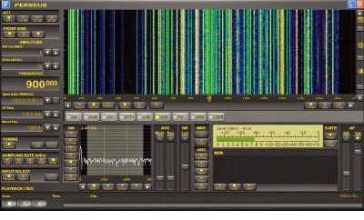
This weekend was the 50MHz Trophy Contest which I was looking forward to, sadly it was also to become a victim of the QRN as this screenshot from my SDR will confirm, for much of the time I was operating I was just listening to noise.

I wasn't operating constantly, just grabbing a few minutes here and there and I did manage to make some decent contacts when the QRN subsided even catching some of the sporadic E opening to get EF7X in Spain.
I have ruled out any noise being generated by myself by powering everything off and running on battery. This leaves me in a bit of a quandary I could go around and locate and confront the culprit or even contact OFCOM but at the same time I don't want to antagonise anyone who could then object to any antennas I might want to put up in the garden.
Rotating the 6M Moxon around at the weekend during the contest as at least pointed me in the direction of one strong noise source. I am also convince that much of my problem is due to an evil PLT device in an adjacent property.
Following on from the weekend last night was the UKAC 50MHz contest and yet again I was troubled with noise leading to mostly local contacts.
I have been looking at some of the noise cancellers that are available from MFJ and others. I have heard conflicting options on their effectiveness but I am willing to try one if I can obtain one cheaply, or even home-brew one from the numerous designs available.
These devices work by using a second antenna which receives just the noise which is then mixed out of phase with the main antenna signal hence nullifying the noise. By all accounts they are tricky to use and often need constant adjustment but may be my only viable solution at present.
Andrew Garratt, MØNRD, is a regular contributor to AmateurRadio.com and writes from East Midlands, England. Contact him at [email protected].
NDB DXing & The CLE183 Results
 |
| WC - 332KHz White Rock, B.C. |
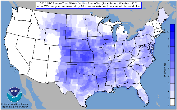 |
| source:http://www.spc.noaa.gov |
One of the beacons in my log this weekend is pictured above - 'WC' in White Rock, B.C. The beacon is located in a residential neighborhood, with homes on both sides...not a typical NDB location.
Here is my short log, all captured using Perseus:
- the challenge of hearing distant low-powered transmitters below the broadcast band, particularly from one region...for me it is Alaskan NDBs
- the necessity to develop an efficient receiving antenna has led to numerous antenna trials using loops and wires in various configurations
- learning about LF propagation and how it compares with HF
- the ability to compare what is being heard at my location with what is heard just a few hundred miles away can often be surprising (and humbling)
If you are planning a 630m station, listening for NDB's is a good way to test your system's receive capability as there are hundreds of signals to be heard, many of them very close to our new 472KHz band.
An informative Introduction To Beacon DXing by Alan Gale may be found here. To find the location of any NDB's that have been heard in North America, check the always accurate RNA database by Martin Francis.
Steve McDonald, VE7SL, is a regular contributor to AmateurRadio.com and writes from British Columbia, Canada. Contact him at [email protected].
LHS Episode #131: The Joy of Ham Radio
 In this episode, we gathered together a small round table to talk about some Linux and ham radio news items, and then discuss the upcoming Field Day, Elmering, and the general joy of amateur radio. Much fun was had by all, and there’s even a cameo appearance by The Richard himself.
73 de The LHS Guys
Russ Woodman, K5TUX, co-hosts the Linux in the Ham Shack podcast which is available for download in both MP3 and OGG audio format. Contact him at [email protected].
Coding for the challenged
Ever since the dawn of time coding has been a foreign language to me. I pick up bits and pieces but largely it gets forgotten or lost.
Tonights issue is about interrupts and debouncing buttons. What better thing to do whilst listening to the 6m white noise contest (also known as vhf from my qth).
The idea is simple. I made a shack clock from a gps and an arduino. I made it tell the time, tell me the position I’m in (no I don’t mean like that) an calculate the locator square. Now then all I want to do is link these together with a simple button press. Press the button and it changes from one function to the next.
Holy arduino, this isn’t straightforward at all. Buttons need debouncing and interrupts don’t like this or that. I feel a long development time in my future…still there’s not much on 6m and 2 contacts in the first hour isn’t going to win me any awards.
Alex Hill, G7KSE, is a regular contributor to AmateurRadio.com and writes from Cumbria, UK. Contact him at [email protected].
Sunspots slowly falling?
Today’s sunspot count is 65 with “normal” 20-30MHz conditions. It looks to me as if the solar activity is now on the slide downwards. This does not mean an end to good conditions. This autumn 15, 12 and 10m should still be in very good shape and it will be a few years before we really see the changes.
There are all sorts of predictions about the next few cycles. The consensus is the next few cycles will be ones with low solar activity. It is still too soon to say if we are really entering another Maunder minimum. Don’t worry: this is a chance to explore HF in different times. There is unlikely to be good (any) E-W F-layer propagation on 12,10 and 6m but N-S propagation will be possible some of the time and openings on Es can be surprisingly distant in all directions at the optimum times of the year.
And there are always VHF, UHF, microwaves and nanowaves to explore!
See the coming months and years as a challenge. We may never see really good conditions again in our lifetimes but there will still be interesting propagation and DX to be worked and heard.
Roger Lapthorn, G3XBM, is a regular contributor to AmateurRadio.com and writes from Cambridge, England.
Alpine storms and Es
I cannot remember the supposed link between Es and thunderstorms (something to do with sprites going upwards from thunder clouds?) but with plenty of thunderstorms in the Alps, I wonder how Es will be tomorrow? Maybe conditions to southern Europe will be good on 6m Es?
Although I probably could safely reconnect antennas this evening now the storms have passed, I think it will be better to wait until the morning.
Knowing my luck, the 6m band will open transatlantic tonight and I shall miss it all! That would not be the end of the world.
Roger Lapthorn, G3XBM, is a regular contributor to AmateurRadio.com and writes from Cambridge, England.
A 1935 Style QSL
 |
| '29 Style Card |
When I next became interested in mid-30's style construction, I decided it was time for another 'era-appropriate' card to match the transmitters. I began searching the web for vintage cards from the mid-30's and soon zeroed in on a card that I found particularly attractive...and from Canada as well.

Once again, Dennis came to the rescue and worked enthusiastically with me to try and duplicate the features and look of the VE4 card that I wanted.
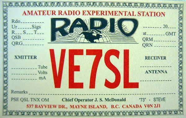 |
| '35 Style Card |
I think he did a super job once again and this past winter the new cards have gone out at a furious pace as I worked many new stations, all on 10m CW with my 6L6 Tri-Tet-Ten.
 |
| 6L6 Tri-Tet-Ten |
If you or anyone you know might be interested in a vintage style card (or any type of card) please get in touch with Dennis. I cannot speak highly enough about him and the quality of his work. You won't be disappointed.
Steve McDonald, VE7SL, is a regular contributor to AmateurRadio.com and writes from British Columbia, Canada. Contact him at [email protected].
 Ham Radio Deluxe |
 W5SWL Electronics |
 Ham Radio Prep |
 KB3IFH QSL Cards  Hip Ham Shirts  HamRadioAuctions HamRadioAuctions Reliance Antennas Reliance Antennas Enigma Shop Enigma Shop |  morseDX  Ni4L Antennas  R&L Electronics R&L Electronics antennas.us antennas.us QRV QRV |
- Matt W1MST, Managing Editor
