 |
 Tuggle-Style LF Regens
 If the name sounds familiar, you may recognize it from reading about the DX crystal radios that Mike Tuggle has created over the past several years. Some might even say that his state-of-the-art and very elegant "Lyonodyne 17" crystal radio re-kindled the modern day interest in crystal radio DXing, once the mainstay of all radio adventures.
 |
| Mike Tuggle's Lyonodyne 17 Crystal DX Tuner |
The challenge was too hard to resist for many and the contest was popular for several years running. Some of the inventive entries for individual years may be seen here. The contest logbooks also make for interesting reading and demonstrate the capability of some of these simple radios.
Although the contest has not been run for the past few years, there is still much interest and discussion of "1AD" radios on Dave Schmarder's "RadioBoard" forum.
Mike's LF tuner is a prime example as he uses it daily and continues to post some amazing DX to the Yahoo "ndblist" Group. His furthest ndb catch in North America with the regen has been "YY" in Mont Joli, Quebec.
Now, "YY" is a good catch for me, from B.C., but Mike is listening from Kaneohe, Hawaii !
You can read about Mike's original design here, while his latest version shown below, incorporates a dedicated LF antenna tuner.
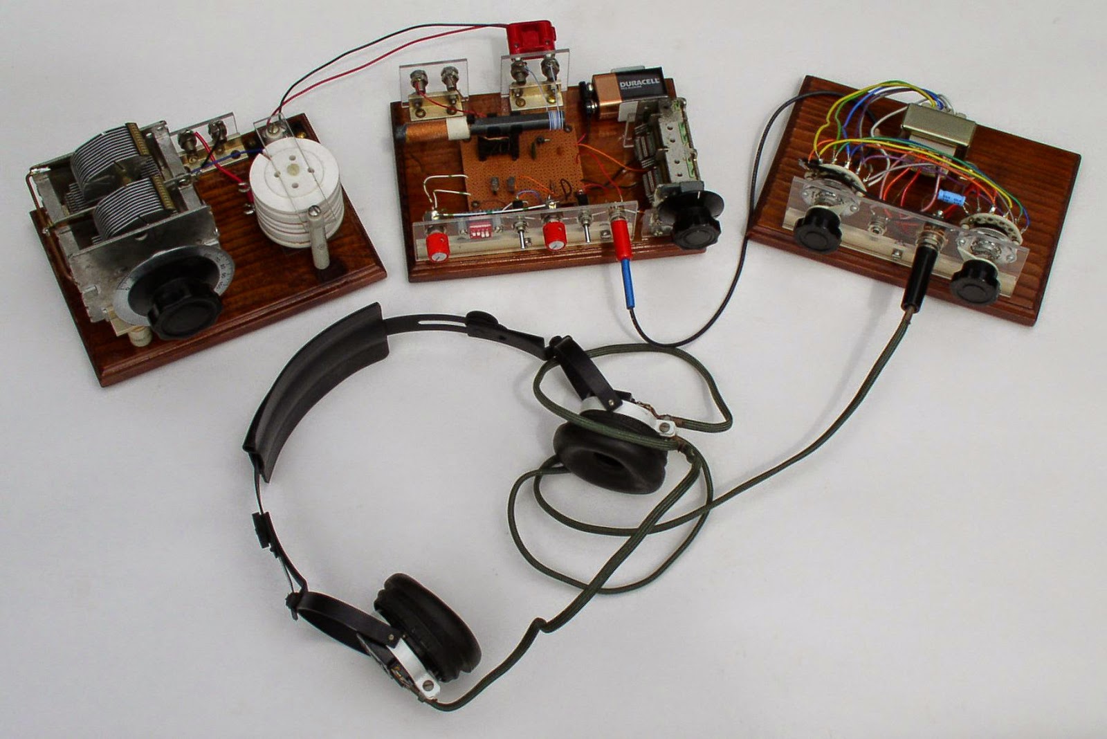 |
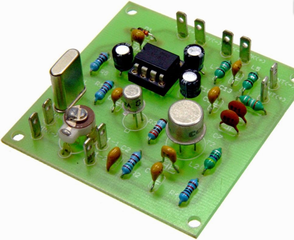
| LF Regen (Courtesy Mike Tuggle) |
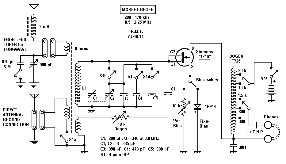 |
| LF Regen Schematic (courtesy Mike Tuggle) |
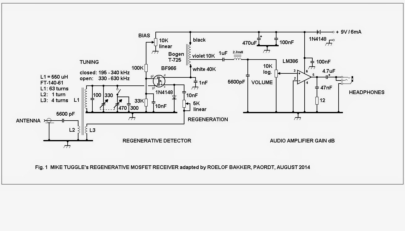 |
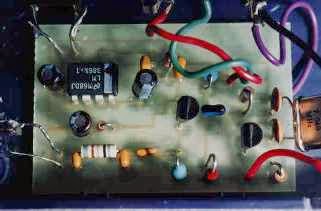
| Courtesy: Roelof Bakker, PAØRDT |
Roelof has also published a nice write-up describing the project which sparked a lot of "must build" discussion within the group.....even enough to make Mike get out his soldering iron and build the European-version!
As old and as simple as they are, regenerative receivers still hold much fascination amongst radio builders and dollar-for-dollar are amazingly good performers, especially on LF.
Steve McDonald, VE7SL, is a regular contributor to AmateurRadio.com and writes from British Columbia, Canada. Contact him at [email protected].
Repairing a Kenwood TR9500, Part1 – The Diagnosis
From the description of the fault and studying a downloaded service manual I suspected a relatively simple fault and saw an opportunity to acquire it and offered to buy it for the price he had paid. However I have decided to be more charitable rather than mercenary and have offered to give it a look over and repair it for him if I can.
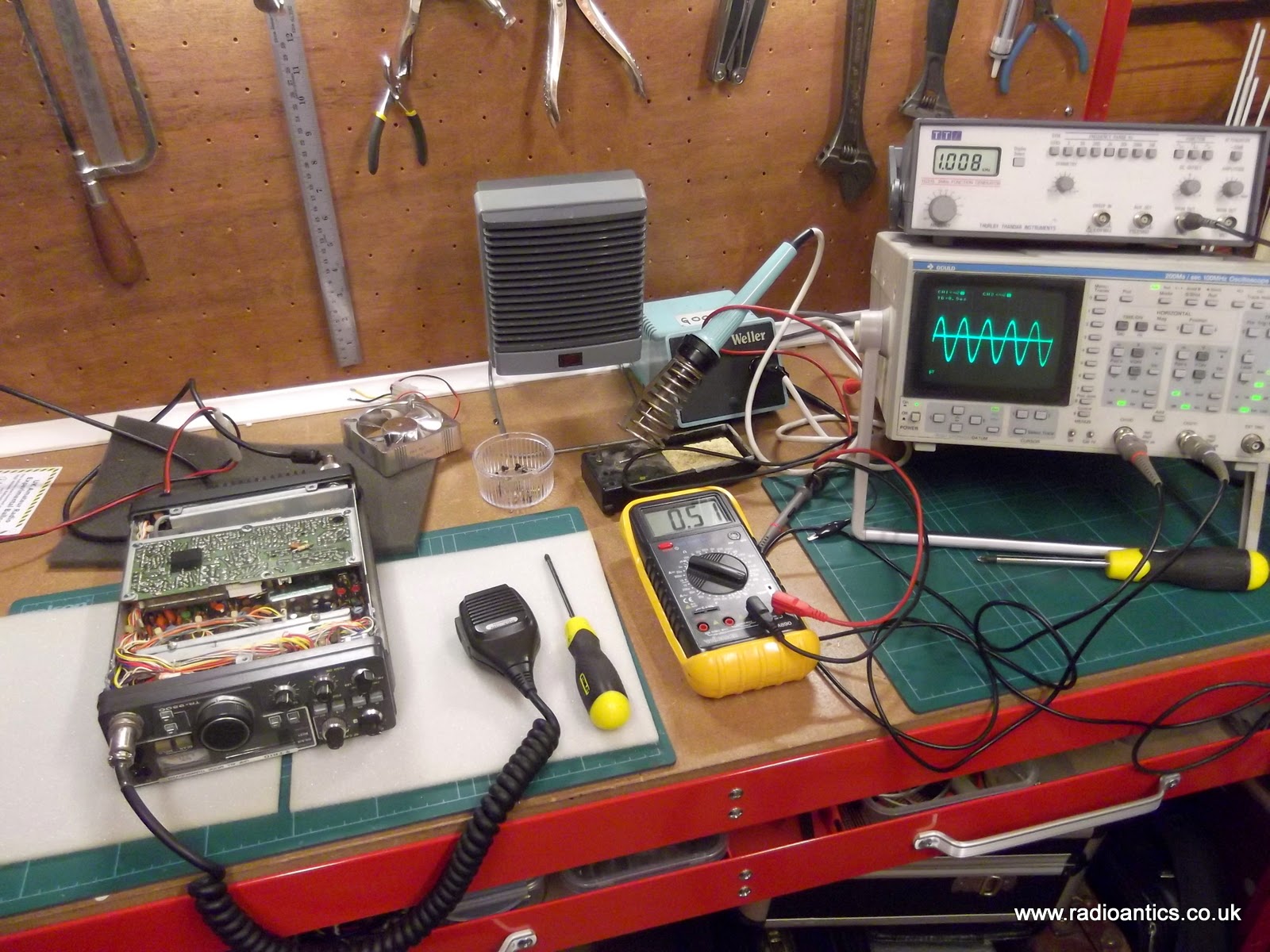
The fault as described was the rig receives okay but on transmit there was a carrier on FM with no audio and a very quiet SSB signal. A faulty microphone had been ruled out and someone had suggested a bad connection internally. Due to the compactness of the unit and the difficulty in dismantling no one had felt confident to attempt any further inspection. I wasn't so sure this was the issue so at the last meeting I picked up the rig and currently have it on the workbench.
TRANSMITTER CIRCUITLooking at the block diagram of the carrier unit and the above functional description in the service manual I suspected the microphone amplifier Q1 to be faulty.
The microphone signal is amplified with the microphone amplifier Q1 (2SC2240(GR)), which is commonly used for both SSB and FM transmission modes and is incorporated in the carrier unit (X50-1720-XX). The amplified signal is then fed to both the SSB and FM circuits.
I want to confirm the fault first and so I connected up a dummy load and RF power meter and using the FUNCube Dongle SDR I could observe and monitor the output signal. Sure enough on FM there was a nice carrier at 10W with very faint audio, on SSB there was a small visible signal again with very little modulation. Whistling, blowing and tapping of the microphone could be seen on the waterfall... just!
I connected a switch to the Morse key input and confirmed the rig transmitted in CW with no issue.

On the block diagram there is a switchable tone burst oscillator for repeater access and the output of this is joined to the output from the microphone amp. Encouragingly the tone burst can be clearly seen and heard in the transmission again pointing to an issue with the microphone amp.
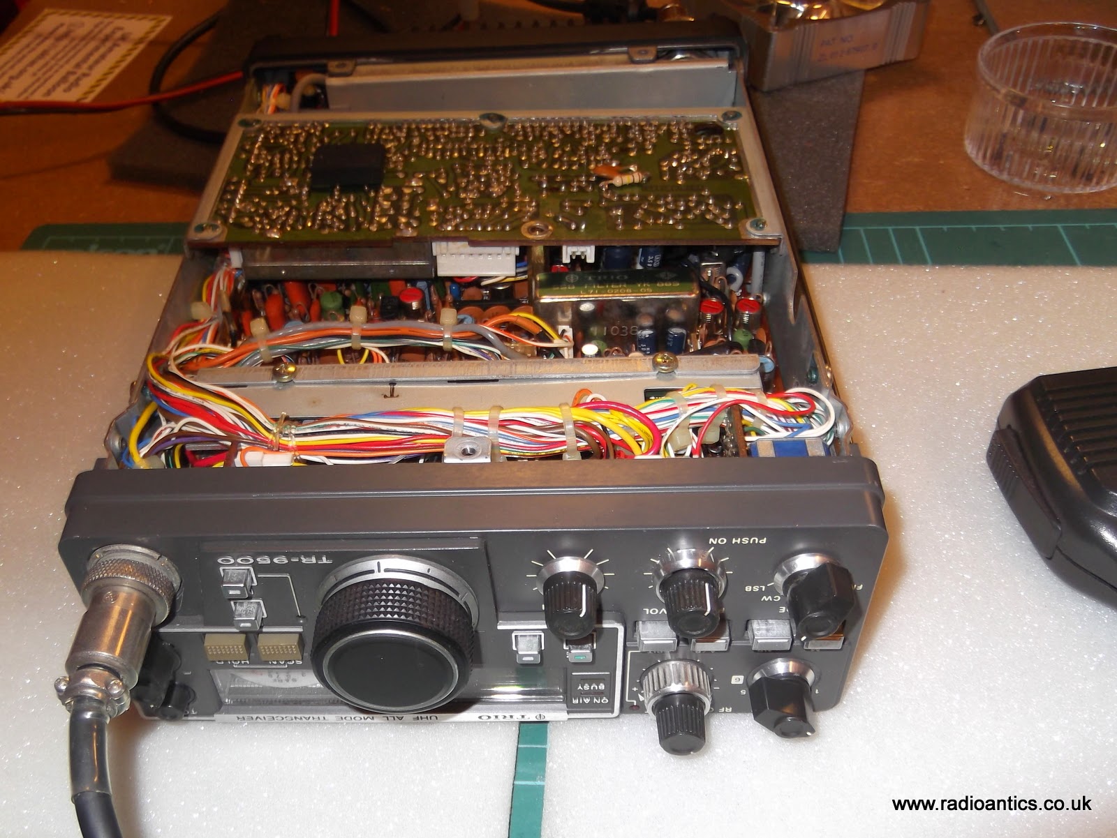
To get to the carrier unit PCB it was a simple matter of removing the bottom cover. The PCB is held in a metal frame mounted with five screws and can be lifted out, as pictured above. But before I did that I checked the continuity to the microphone socket and the 8V supply to the amplifier circuit and both were fine (see diagram below)
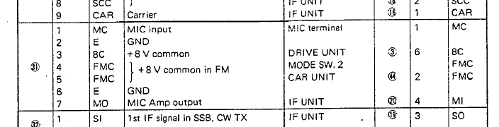

The poor quality image from the scanned service manual shows the bottom of the carrier unit, this is the side of the PCB visible without needing to remove it. The microphone connector is in the top left, putting an oscilloscope on the microphone input (pin1) a signal was observed, however the output (pin8) had an almost identical signal with little or no amplification. Injecting a low level audio signal from the a generator on this pin could be seen and heard in the transmitted signal. This observation together with the tone burst seemed to confirm the other audio circuitry was functioning normally and the microphone amp wasn't.
Actually removing the carrier unit PCB proved a bit tricky as it has a number of small and very secure connectors with ageing and delicate wiring, but I did manage to extricate it and a visual inspection didn't show up any obvious issues such as broken tracks or joints.

This is the detail of the microphone amplifier section from the schematic. Using a meter I have checked the continuity of tracks and have checked all the resistors for shorts or open circuits and they all read the correct values. The capacitors all look okay and checking the signals either side of C3 the C7 coupling capacitors show they are functioning correctly. This left Q1 a 2SC2240(GR) transistor as the likely culprit and I have ordered a replacement which should arrive in the next few days. I am hoping this will make it spring back to life.
Andrew Garratt, MØNRD, is a regular contributor to AmateurRadio.com and writes from East Midlands, England. Contact him at [email protected].
Amateur Radio Newsline Report 1934 September 5 2014
- Japan space mission to asteroid will carry a ham radio satellite
- New study challenges the so-called broadband spectrum crunch
- DXpedition to Navassa Island within the next 18 months
- AMSAT-NA adds an auction at its upcoming space symposium
- Pirate radio causing aviation safety concerns in China
DX from the Seashore
Judy and I drove over to the beach today… and what a day it was! We had a beautiful walk on the beach. I worked Bulgaria, France, Italy, TN and GA with a wire that was only three feet off the ground!

We brought our bikes and after a picnic lunch we rode a few miles up the road and back along the shore. Judy picked rose hips (rich in vitamin C) from the wild Rosa Rugosa along the way. It was in the low 80s F with just a little breeze. After that we sat on some benches in front of Rye Harbor. Judy lay down in the sun, and I strung a wire from the bench to a low bush that was 40 feet behind us. At most the wire was only 3 feet above the ground. I’d brought the kite, but there wasn’t enough wind to fly it. So I used what was available.

I had brought the KX3 and tuned around 20 meters and heard a couple of strong stations… the first one was W1AW/4 in TN. What the heck, I thought… I’ll give it a try. I got an answer on the first call and completed the exchange. Whooppee! TN on a 30 foot wire 3 feet off the ground. Next I worked Tony W4FOA in Georgia. He also gave me a 599. Now I was feeling pretty confident and went down the band for some DX. IK1ZNL, Paolo in Italy was 579. He answered my call and gave me a 559. Yikes… DX with a low wire. Then I worked LZ37MP in Bulgaria. I was working DX with the nicest view in the world…. Rye Harbor.

I thought I’d see what 30 meters was like. The Europeans were working each other all over the band, and they were strong! So I called a few… but no luck. I was hearing them, but their local signals were much stronger than I was. Anyway, I worked Chris F8DGY in France on 30 and completed the exchange, but clearly he wasn’t hearing me very well. But what the heck… I simply couldn’t ask for more. A perfect day, a beautiful beach and some DX by the sea.

Jim Cluett, W1PID, is a regular contributor to AmateurRadio.com and writes from New Hampshire, USA. Contact him at [email protected].
So you want to play with a Pixie?
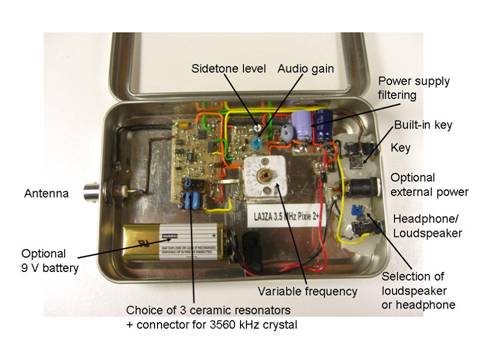 |
| My own surface mount version of the Pixie2 |
This page provides a guide to Pixie and related kits in a table format. These are simplistic single-band transceivers which are fun to build, yet they perform well enough to be used, although with some effort, for real contacts.
The idea of using the power amplifier transistor as a mixer seems to come from George Burt – GM3OXX – whose five transistor FOXX was described in 1983 in SPRAT. The basic design of the oscillator, PA/mixer and the simple keying has been more or less unchanged since RV3GM – Oleg Borodin – described the four transistor Micro-80 in 1992 in SPRAT. Later the Pixie 2 by WA6BOY replaced two of those transistors with the LM386 audio amplifier (QRPp 1995). Most later versions are variants of these designs.
Foxx | |
 Foxx-3 kit from Kanga, £29.95 | Incorporates a sidetone oscillator, changeover relay and low-pass filter. Different versions for the 80, 40, 30 or 20 m bands |
Micro-80 | |
 Kit from QRPme, $35.00 | Micro80D. Updated version with choice of high or low impedance headphone, polyvaricon tuning cap and board mounted connectors, 80 m. |
Pixie2 | |
 Kit from HSC Electronic Supply, $14.95 | For 80 and 40 m. Eham review |
 Kit from Kenneke, $29.95 | Includes 80 m crystal |
 Kit from QRPme, $40.00 | Lil Squall Transceiver ][. Several components and the output low pass filter are on sockets. Comes with a crystal for 40 m. |
 Ali Express Ham QRP DIY Kit Shack 40 m, $15.07 | 40 m version. Tuning pot for VXO. |
 Radi0kit, £22.00 | Enhanced Pixie2 which comes in 80, 40 and 20 m versions. Judging from the PCB layout it has an improved pin 7 muting circuit. |
What can we say to characterize these designs? One the one hand they are very simple to build and get to work. One the other hand they are also simple in the sense that they do not always perform very well. Therefore I don’t think I would recommend them to any novice ham. It takes some understanding of frequency offsets and sidebands in order to make real contacts. But many have had great fun with this minimalist transceiver which in its basic version puts out some 2-300 mW. And it encourages experimentation and modifications. Also, it should be remembered that it isn’t really necessary to get a kit, as the Pixie 2 is quite simple to build from scratch also. I did that myself.
The original designs and many variants and modifications are documented in the Pixie file document of SPRAT. There are many, many more clever modifications out there and I have my share on this blog also. To sort out and link to all the other pages is too daunting a task, so therefore I have focused on kits here. Finally I wouldn’t be surprised if the table is incomplete so I would appreciate comments if you think that something is missing.
Sverre Holm, LA3ZA, is a regular contributor to AmateurRadio.com and writes from Norway. Contact him at [email protected].
I’ll admit, I fell for it!
This from the ARRL today:
ZCZC AG16
QST de W1AW
ARRL Bulletin 16 ARLB016
>From ARRL Headquarters
Newington CT September 4, 2014
To all radio amateurs
SB QST ARL ARLB016
ARLB016 New Amateur Radio Vanity Call Sign Fee Set at $21.40
The FCC has adjusted very slightly downward - to $21.40 - its proposed Amateur Service vanity call sign regulatory fee for Fiscal Year 2014. In a June Notice of Proposed Rule Making (NPRM), the Commission said it was planning to hike the current $16.10 vanity fee to $21.60 for the 10-year license term. The FCC released a Report and Order and Further Notice of Proposed Rulemaking (R&O) in the proceeding on August 29, in which it recalculated the fee to $21.40 for the 10-year license term. The $5.30 increase still represents the largest vanity fee hike in many years.
The new $21.40 fee does not go into effect until 30 days after the R&O is published in The Federal Register.
In the R&O, the FCC said it considered eliminating the regulatory fee for Amateur Radio vanity call sign applications but decided not to do so "at this time," because it lacks "adequate support to determine whether the cost of recovery and burden on small entities outweighs the collected revenue; or whether eliminating the fee would adversely affect the licensing process." The Commission said it would reevaluate this issue in the future to determine if it should eliminate other fee categories.
The FCC's Wireless Telecommunications Bureau sets the vanity call sign regulatory fee using projections of new applications and renewals, taking into consideration existing Commission licensee databases, such as the Universal Licensing System (ULS) database.
The FCC reported there were 11,500 "payment units" in FY 2014. The Commission said the vanity program generated an estimated $230,230 in FY 2013 revenue, and it estimated that it would collect nearly $246,100 in FY 2014.
The vanity call sign regulatory fee is payable when applying for a new vanity call sign or when renewing a vanity call sign, although some older vanity call signs are not subject to the regulatory fee.
NNNN
/EX
I wonder what the fee will be in 2020 when it's time for me to renew again! I think it was around $14 in 2010 when I last renewed. Oh well, if you want to dance, you have to pay the piper, I guess.
I love this part, though. "In the R&O, the FCC said it considered eliminating the regulatory fee for Amateur Radio vanity call sign applications, but decided not to do so "at this time," because it lacks "adequate support to determine whether the cost of recovery and burden on small entities outweighs the collected revenue; or whether eliminating the fee would adversely affect the licensing process." Translation - "Naaah! We decided to raise it by $5.30 instead."
Ya just gotta love the Federal Government!
72 de Larry W2LJ
QRP - When you care to send the very least!
Larry Makoski, W2LJ, is a regular contributor to AmateurRadio.com and writes from New Jersey, USA. Contact him at [email protected].
The TX Factor Team Goes Continental!
Nick Bennett 2EØFGQ co-hosts TX Factor with Bob McCreadie GØFGX and Mike Marsh G1IAR. Contact the team at [email protected]
 Ham Radio Deluxe |
 W5SWL Electronics |
 Ham Radio Prep |
 KB3IFH QSL Cards  Hip Ham Shirts  HamRadioAuctions HamRadioAuctions Reliance Antennas Reliance Antennas Enigma Shop Enigma Shop |  morseDX  Ni4L Antennas  R&L Electronics R&L Electronics antennas.us antennas.us QRV QRV |
- Matt W1MST, Managing Editor
