 |
 VLF amateur radio
Being involved in VLF amateur radio is a very specialised activity requiring special (but low cost) kit to be successful. Casual listening is highly unlikely to be successful. Long distance reception of amateur VLF signals usually involves looking for signals using Spectrum Laboratory software locked to a VLF MSK signal so that very narrow bandwidths can be looked at for hours or days on end.
Most amateur VLF tests are done on 8.27kHz as this is unallocated spectrum in many countries.
News about amateur VLF activity can be found at https://sites.google.com/site/sub9khz/ . There has been very little amateur VLF work done this year but amateur VLF signals have crossed the Atlantic.
Tests using utilities assisted earth-mode do not involve big loading coils. Just under 6km has been achieved with just 5W using this mode, before I had my stroke! The kit was simple too. See https://sites.google.com/site/sub9khz/earthmode .
One of the things I am really looking forward to, when fit again, is some more field work with VLF using earth-mode.
Roger Lapthorn, G3XBM, is a regular contributor to AmateurRadio.com and writes from Cambridge, England.
BK Bustle
You may hear plenty of activity in the nights leading up to the Party as various stations burn the cobwebs out of their handmade creations around 3550-3570 in the next few nights...you might give them a call if you hear them as most will be delighted to know that they're getting out of their backyard.
A few weeks ago, in the same spirit of preparation, I began work on a small amplifier for my Hull Hartley transmitter. Ever since entering the BK Party, I have been held hostage by the monster winds which always seem to show up here during early December. Self-excited oscillators connected to blowing antennas create an unusual-sounding signal...somewhat musical....up to about 30km, but after that, somewhat dreadful, as shifts in frequency between keying elements can be measured in tens of Hertz or more and make it difficult to copy a weak signal.
I put the amp together in the original 'ugly construction' style of the 20's, which I'll call 'ugly breadboard'. For the most part, period-appropriate components were used, as it was to be a 'proof-of-concept' project....to see if and how it would work and what changes might need to be implemented in a 'finished' version.
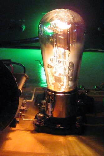
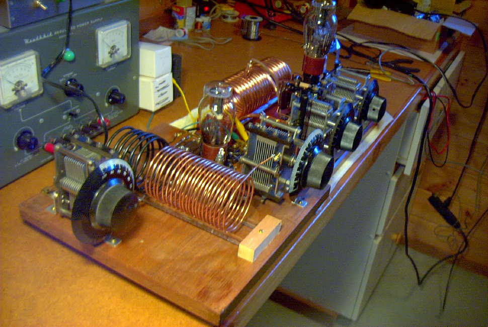 t t |
| Amplifier stage followed by Hull Hartley exciter on far end. |
The original circuit, shown below, was published in the February 1931 QST and penned by George Grammer (W1DF), the ARRL's Assistant Technical Editor. Since I already had the oscillator section, I built the amplifier only, making a few modifications.
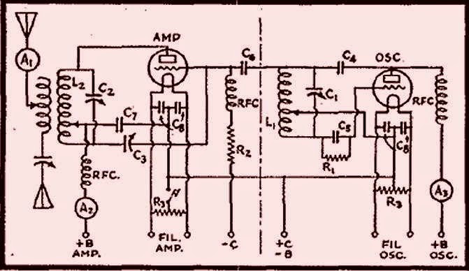 |
| Courtesy: http://www.arrl.org/ |
My changes involved removing the B+ from the exposed plate tank coil by putting C7 between the plate and the tank circuit, grounding the coil tap point and shunt-feeding the B+ directly to the plate. As well, the operating bias was changed from the original combination of grid-leak and external fixed-bias (always a pain) to grid-leak bias only. Since I planned to let the oscillator run and key only the amplifier stage, no external (extra) bias was needed. The original system of feeding drive via capacitive coupling from the oscillator tank circuit was maintained as was the 'plate neutralizing' system. With the plate tank no longer carrying B+, a wide-spaced variable capacitor was no longer required for C3. These changes are illustrated below:
 |
| Courtesy: http://www.arrl.org/ |
Testing went smoothly and with the help of a tuned RF-sniffing wavemeter (the actual one I built when I was a brand new15 years old ham!), the amplifier neutralized beautifully. It was unconditionally stable, in spite of the numerous clip leads surrounding the board connecting to the separate Hartley oscillator in a somewhat haywire fashion....it really was a mess. As one other '29 builder (KK7UV) so perfectly described his latest workbench project, it "looked like the transmitter was on life-support!"
Surprisingly little drive was required from the Hartley and it was run at just 200VDC. The amplifier efficiency was around 50% which could probably be improved upon with careful attention to biasing values, shorter leads and more efficient antenna coupling. On 80m, the only band that I wound a coil for, keying was clean and very nice (an advantage of being able to run the oscillator at low level). Without too much effort, 15 watts out was easily obtained...far too much for the BK Party.
Tapping down on the tank coil for 40m operation proved to be a different story as the note sounded like a buzz saw...very raspy and nasty. To really undertake a fair test, a dedicated 40m tank coil would have to be used as well as a much 'cleaner build'.
The rat's nest of unwanted coupling of both RF and AC ripple was showing through on this higher frequency.
For multiband operating events, such as the BK, things have to be efficient enough to make band changing and tune-up procedures quick and simple and in its present haywire form, the amplifier would just not be 'contest-friendly'.
All in all it was a very valuable building exercise as a LOT was learned. I am now convinced that for a true MOPA (Master Oscillator Power Amplifier) combination to do what is needed will require an all-in-one style of construction....both oscillator and amplifier on the same board, with short leads and little chance for unwanted parasitic-coupling between stages. With separate coils for all bands and calibrated dials, tuning and changing bands would be very much easier than trying to couple two separate units together. I can see why the struggle to get the original '29ers away from their simple Hartley's and TNT's and over to MOPAS went on for several years.

So once again I am at the mercy of the wind-gods and hoping for two back-to-back Saturdays of quiet BK-friendly air...in early December...on the west coast...by the ocean...yeh, right!
Steve McDonald, VE7SL, is a regular contributor to AmateurRadio.com and writes from British Columbia, Canada. Contact him at [email protected].
FISTS / SKCC Joint Sprint this Saturday

Looks like I'll have to get some bug practice in before the weekend. This is going to be a toughie, though - a Saturday afternoon before Christmas. I definitely won't be able to put in a full four hours, but I am a member of both organizations and I do need to start working on my SKCC Tribune award. I've been treading water as a Centurion for years now.
Larry Makoski, W2LJ, is a regular contributor to AmateurRadio.com and writes from New Jersey, USA. Contact him at [email protected].
QRPme website
See www.qrpme.com .
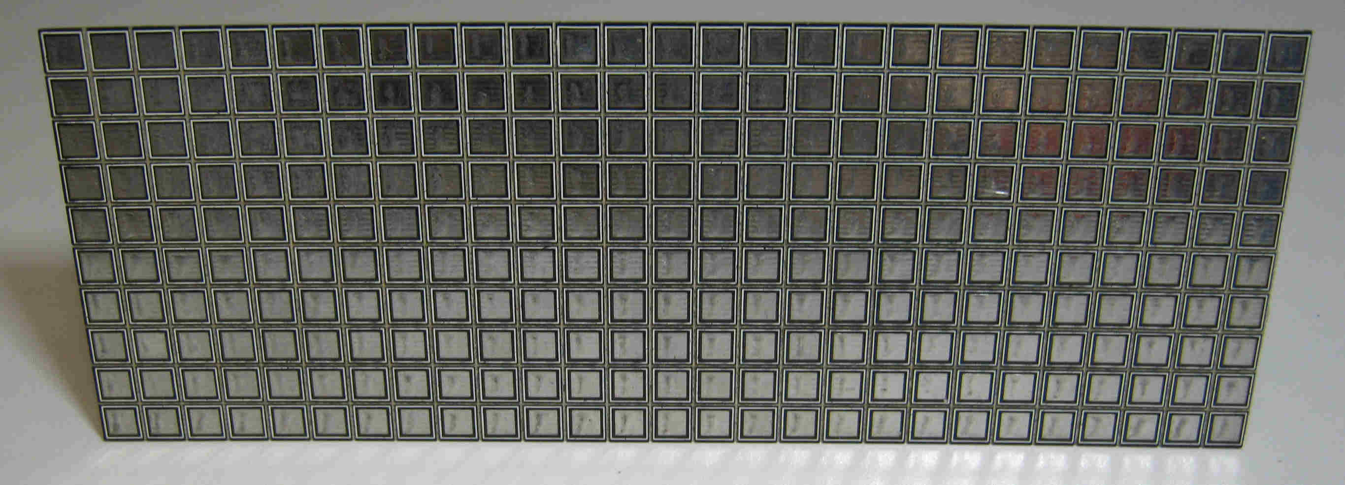 |
| http://www.qrpme.com/images/MeSquares.jpg |
Always on the look out for interesting QRP projects, the QRPme website has lots of interesting and low cost projects. They also sell crystals for QRP frequencies and MePads and MeSquares, which are very useful. In all, a useful resource for keen QRP enthusiasts.
Roger Lapthorn, G3XBM, is a regular contributor to AmateurRadio.com and writes from Cambridge, England.
Some common sense, please!
Take for instance last night. I was trying to work Steve WX2S on 40 Meters who lives about 18 miles from me. Ground wave was strong enough that he was about a 229/339. The advantage was that not only could I hear him, but I could also hear the stations that were calling him. I ended up not working him, but even so, it was a unique opportunity to observe.
Steve was working split from the beginning and he was handling the pile up deftly. But I was left shaking my head, because so many times - all through the hunt, people continued throwing out their calls while Steve was engaging another station! I sat there, kind of dumbfounded. There was Steve, sending out "559 NJ STEVE 5W" to whomever, and all the while there were stations sending out their calls, over and over and over, without so much as taking a breath!
So here's the deal......if you can't hear the quarry well enough to realize he answered someone other than yourself - then why the heck do you continue to throw your call sign out there in the first place? Obviously, if by some miracle, he actually came back to you - would you be able to hear that well enough to realize it and complete the exchange? Something tells me ........no.

Listening. That seems to be a dirty word in the minds of a lot of folks.
Look, I know we all make mistakes and I've made my fair share, too. No one is perfect, and I can understand forgetting to turn the "split" function on or some other such thing. But deliberately sending your call over and over and over in the vain hope of somehow scatter-gunning the target is really just inexcusable, and rude and inconsiderate of your fellow Hams.
As always, this is just my humble opinion. Your mileage may vary.
72 de Larry W2LJ
QRP - When you care to send the very least!
Larry Makoski, W2LJ, is a regular contributor to AmateurRadio.com and writes from New Jersey, USA. Contact him at [email protected].
How About a New 12 Volt Automotive Connector?
 Don’t get me wrong — I do like standard connectors. A while back, I wrote about how the micro-USB connector became the standard power/data connector for mobile phones. Well, that is unless you own an iPhone.
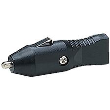
The good news is that we do have a standard power connector for 12 VDC in automobiles. The bad news is that it is an ugly behemoth derived from — can you believe it? — a cigarette lighter. For some background and history, see the Wikipedia article. The Society of Automotive Engineers (SAE) has a standard that describes this power connector (SAE J563). Alan K0BG correctly warns us to “never, ever use existing vehicle wiring to power any amateur radio gear” including the 12 volt accessory plug. (I always follow this advice, except in the cases when I don’t.) I also found this piece by Bill W8LV on eham.net that describes the crappiness of these connectors.
Well, there is a new standard power connector showing up in cars: the USB port. These ports provide the data and power interface for mobile phones, integrating them into the auto’s audio system. Standard USB ports (USB 1.x or 2.0) have a 5V output that can deliver up to 0.5A, resulting in 2.5W of power. A USB Charging Port can source up to 1.5A at 5V, for 7.5 W of power. This is not that great for powering even low power (QRP) ham radio equipment.
Now a new standard, USB Power Delivery, is being developed that will source up to 100W of power. The plan is for the interface to negotiate a higher voltage output (up to 20V) with 5A of current. Wow, now that is some serious power. We will have to see if this standard is broadly adopted.
Two things are obvious to me: 1) the old cigarette lighter connector needs to go away and 2) it is not clear what the replacement will be.
What do you think? Any ideas for the next generation of 12V automotive connector?
73, Bob K0NR
The post How About a New 12 Volt Automotive Connector? appeared first on The KØNR Radio Site.
Bob Witte, KØNR, is a regular contributor to AmateurRadio.com and writes from Colorado, USA. Contact him at [email protected].
ITU Plenipotentiary Meeting – Busan Korea 2014
I have not had a chance to wade through the report(s) from this ITU meeting in Korea ahead of WRC2015 to see if a contiguous 60m band amateur allocation is any more probable. The few bits I did read were talking about budgets! We certainly will need a contiguous 60m band in the quiet years ahead. A nice new worldwide amateur band there would be very welcome.
Roger Lapthorn, G3XBM, is a regular contributor to AmateurRadio.com and writes from Cambridge, England.
 Ham Radio Deluxe |
 W5SWL Electronics |
 Ham Radio Prep |
 KB3IFH QSL Cards  Hip Ham Shirts  HamRadioAuctions HamRadioAuctions Reliance Antennas Reliance Antennas Enigma Shop Enigma Shop |  morseDX  Ni4L Antennas  R&L Electronics R&L Electronics antennas.us antennas.us QRV QRV |
- Matt W1MST, Managing Editor
