 |
 All continents in one night on WSPR
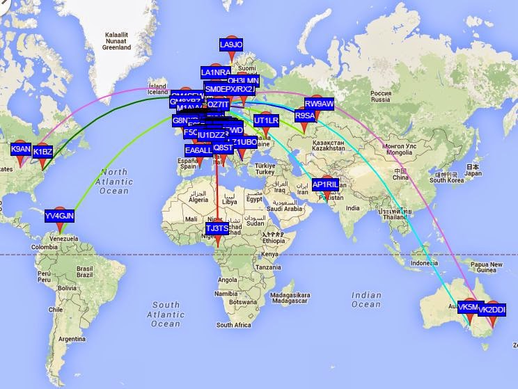
For me South America, Australia, and Africa are quite rare on WSPR. But they all heard my tiny 0.2 W signal the night between 31 March and 1 April in addition to North America, Asia and Europe. That’s a new one for me and worthy a brag post on the blog, I think! Hopefully, it may also inspire others to try low power WSPR.
In Australia and South America I was heard on the 10 MHz band, in Africa on 21 MHz, in Pakistan on 14 MHz, while 7 and 10 MHz worked into Siberia. North American stations also heard me on the 7 and 10 MHz bands.
This was on my untuned 80 m horizontal loop fed with open-wire feeder and a 4:1 balun. This shows both that the bare-foot Ultimate 3 kit is very tolerant of loads with SWR much different from 1, and that WSPR gives amazing results.
Sverre Holm, LA3ZA, is a regular contributor to AmateurRadio.com and writes from Norway. Contact him at [email protected].
All continents in one night on WSPR
For me South America, Australia, and Africa are quite rare on WSPR. But they all heard my tiny 0.2 W signal the night between 31 March and 1 April in addition to North America, Asia and Europe. That’s a new one for me and worthy a brag post on the blog, I think! Hopefully, it may also inspire others to try low power WSPR.
In Australia and South America I was heard on the 10 MHz band, in Africa on 21 MHz, in Pakistan on 14 MHz, while 7 and 10 MHz worked into Siberia. North American stations also heard me on the 7 and 10 MHz bands.
This was on my untuned 80 m horizontal loop fed with open-wire feeder and a 4:1 balun. This shows both that the bare-foot Ultimate 3 kit is very tolerant of loads with SWR much different from 1, and that WSPR gives amazing results.
Sverre Holm, LA3ZA, is a regular contributor to AmateurRadio.com and writes from Norway. Contact him at [email protected].
Out and about with my KX3 radio
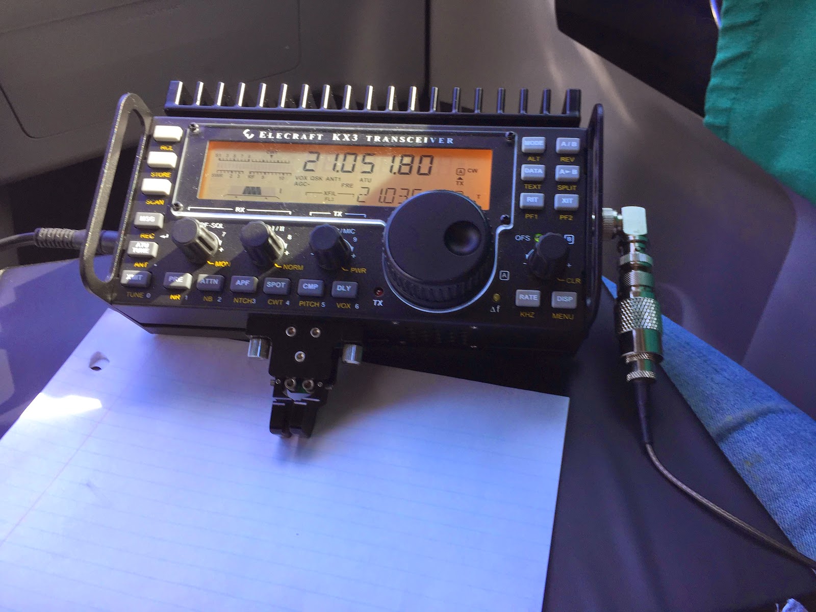 |
| The KX3 being used in my lap. |
1. I1YRL from Italy and Luc was very strong and no fading what so ever. While talking to him I found out that in the summer of 2014 he and his wife visited Toronto. Luc gave my 5 watt QRP signal a report of 579. Luc was very surprised I was QRP 5 watts using a mobile whip from my car.
2. EG90IARU/5 this was a special event again they were booming in and I was able to make the contact on my first call. This was a very fast contact with the usual 599 report.
3. IT9NJE and Gene again from Italy gave me a 549 signal report.
Over all I was very pleased with my hour on the radio from the car out in the park. I was happy I did not have any Murphy moments but I did have an "old age" moment..................I installed the 15m mono band whip antenna on the car. For some reason (old age) I set the KX3 to 20m and could not understand why the antenna tuner was needed everywhere on the band! Then in occurred to me I was on 20m using my 15m antenna. Once that was sorted out the morning went very well.
Mike Weir, VE9KK, is a regular contributor to AmateurRadio.com and writes from New Brunswick, Canada. Contact him at [email protected].
CQ World Wide WPX SSB – QRP Style
 |
| Nick KE0ATH Spinnin’ the dial! |
It has been way to long since I have posted here on the blog, and really I have done very little operating!
This past weekend was the CQ World Wide WPX SSB contest. My son Nick, KE0ATH has been trying off and on to make some contacts on 10 meters since he is a Tech. I thought this contest would be great for him, so we carved out about 45 minutes on Sunday to get on the air.
Tuning around 10 meters we heard some stations calling CQ without many takers, it was late in the contest. Some of the stations we worked had like 3,000 contacts, and were handing out #001! 🙂
We ended up working exclusively into South America. Nick would give them a call, and when he was successful I would give them a call. Great fun!
We have the KX3 set at 12 watts into my 66″ dipole fed with ladder line. Tunes up great.
If you look at the picture of the rig, you can see the stand that Nick 3D printed for me to hold the KX3. He designed it in Autodesk Inventor and printed it – it also has my call sign inlayed into it in the lower right hand corner. It works perfectly!
We worked everyone that we called as well.
We worked just 6 stations, but it was fun. Here is who we worked:
PY3KN Brazil
NR6O California USA
PJ2T Cuaraco
CE3CT Chile
HK3C Columbia
8P5A Barbados
It was great fun, and Nick had a blast working his first HF contacts! Plus I picked up several new DXCC entities for myself!
Burke Jones, NØHYD, is a regular contributor to AmateurRadio.com and writes from Kansas, USA. Contact him at [email protected].
CQ World Wide WPX SSB – QRP Style
|
| Nick KE0ATH Spinnin’ the dial! |
It has been way to long since I have posted here on the blog, and really I have done very little operating!
This past weekend was the CQ World Wide WPX SSB contest. My son Nick, KE0ATH has been trying off and on to make some contacts on 10 meters since he is a Tech. I thought this contest would be great for him, so we carved out about 45 minutes on Sunday to get on the air.
Tuning around 10 meters we heard some stations calling CQ without many takers, it was late in the contest. Some of the stations we worked had like 3,000 contacts, and were handing out #001! 🙂
We ended up working exclusively into South America. Nick would give them a call, and when he was successful I would give them a call. Great fun!
We have the KX3 set at 12 watts into my 66″ dipole fed with ladder line. Tunes up great.
If you look at the picture of the rig, you can see the stand that Nick 3D printed for me to hold the KX3. He designed it in Autodesk Inventor and printed it – it also has my call sign inlayed into it in the lower right hand corner. It works perfectly!
We worked everyone that we called as well.
We worked just 6 stations, but it was fun. Here is who we worked:
PY3KN Brazil
NR6O California USA
PJ2T Cuaraco
CE3CT Chile
HK3C Columbia
8P5A Barbados
It was great fun, and Nick had a blast working his first HF contacts! Plus I picked up several new DXCC entities for myself!
Burke Jones, NØHYD, is a regular contributor to AmateurRadio.com and writes from Kansas, USA. Contact him at [email protected].
First (restarted) VLF earth-mode test
 |
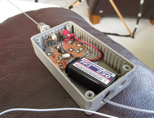
| 5W VLF beacon TX |
OK, I was only testing from the shack to the lounge, but this is a start. TX is 5W from my TDA2003 beacon.
TX frequency 8.976kHz initially with 10wpm CW, 300Hz bandwidth, sending my callsign and a dash. Nothing copied at first using a dummy load but over 70dB over noise using the earth-electrode “antenna” with no attempt to optimise match (fed via the same 3C90 step-up transformer used on 472kHz). With no probe at all (i.e.no RX antenna) the S/N was still some 40dB i.e. very good using the TX into the earth-electrodes.
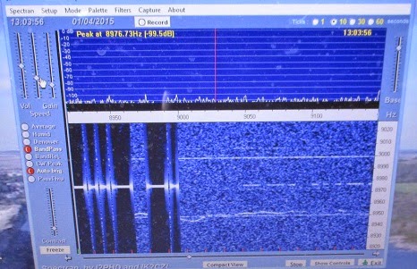 |
| QRSS3 signal received on Spectran (0.37Hz BW) |
Later with QRSS3, a 50 ohm TX dummy load, E-field probe at the RX, I got the signal at 10-20dB S/N. At the RX end I was using my simple E-field probe into a USB soundcard into my Windows 8.1 laptop.
 |
| E-field probe |
The blue photo shows the signal at the RX. The first part shows the TX signal on the earth-electrodes and the second part (weaker) was the signal on the EFP with the TX into a dummy load.
Honestly, this has really exhausted me!
Roger Lapthorn, G3XBM, is a regular contributor to AmateurRadio.com and writes from Cambridge, England.
Grinding quartz and holding a frequency during World War II
I’m a great fan of the Prelinger Archives which is home to so many items like this video I’ve heard about recently from various ham radio email lists.
I like how the components of the earliest electronics and wireless were so basic and ‘natural’. Think of hand made capacitors and resistors using traces of graphite on paper. Valves (or tubes) of course were another story but still capable of being ‘homemade‘.
I love the idea that an accurate, literally rock solid frequency could be achieved using a piece of a very common rock – admittedly a pure piece of quartz cut just so.
This video details the elaborate and meticulous manufacture of quartz crystals during World War 2 by Reeves Sound Laboratories in 1943.
The 41’24” video can also be viewed and downloaded via the Prelinger Archives.
Most of the ‘radio quality’ quartz was mined in Brazil which ceased its neutrality in 1942 and joined the Allies.
The story of quartz crystals during WWII is told in ‘Crystal Clear‘ by Richard J. Thompson Jr. (Wiley) 2011.

“In Crystal Clear, Richard Thompson relates the story of the quartz crystal in World War II, from its early days as a curiosity for amateur radio enthusiasts, to its use by the United States Armed Forces. It follows the intrepid group of scientists and engineers from the Office of the Chief Signal Officer of the U.S. Army as they raced to create an effective quartz crystal unit. They had to find a reliable supply of radio-quality quartz; devise methods to reach, mine, and transport the quartz; find a way to manufacture quartz crystal oscillators rapidly; and then solve the puzzling “ageing problem” that plagued the early units. Ultimately, the development of quartz oscillators became the second largest scientific undertaking in World War II after the Manhattan Project.” (from the book’s blurb)

 Ham Radio Deluxe |
 W5SWL Electronics |
 Ham Radio Prep |
 KB3IFH QSL Cards  Hip Ham Shirts  HamRadioAuctions HamRadioAuctions Reliance Antennas Reliance Antennas Enigma Shop Enigma Shop |  morseDX  Ni4L Antennas  R&L Electronics R&L Electronics antennas.us antennas.us QRV QRV |
- Matt W1MST, Managing Editor
