 |
 MFJ 1788 vs Weather
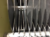
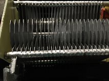
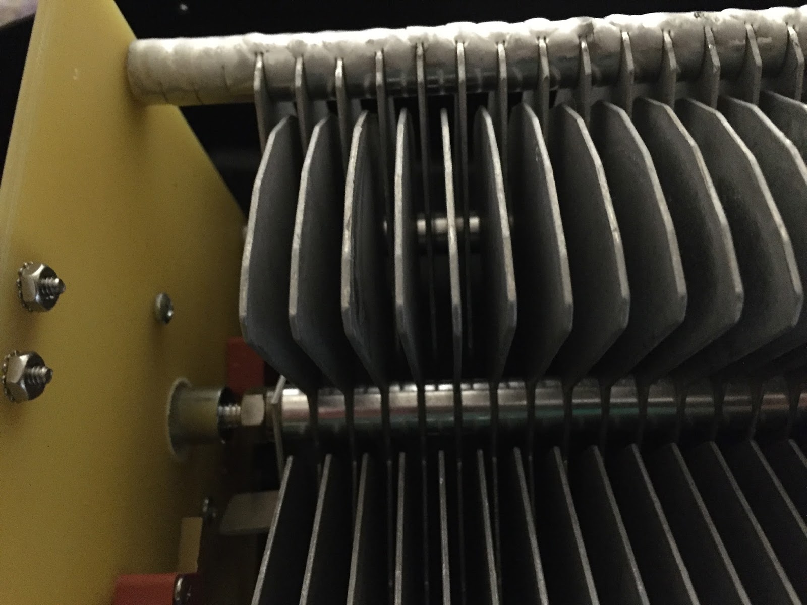
7. I then put the plastic cover back on and again check the SWR on all bands, I wanted to make sure nothing changed……. nothing did change and all was still good.
Below is one section of the fins that have been adjusted and are back to normal position.
Mike Weir, VE9KK, is a regular contributor to AmateurRadio.com and writes from New Brunswick, Canada. Contact him at [email protected].
RSGB grants permission to use images of book covers.

At the time of writing I didn't have permission from the RSGB to include images from their books.. However I have recently been in touch with the RSGB and have been granted permission to include them on my blog, subject to asking at the time I require.
Thank you
RSGB Commercial & Membership Manager
That particular blog has now been updated with the cover image, see link above.
Steve, G1KQH, is a regular contributor to AmateurRadio.com and writes from England. Contact him at [email protected].
RSGB grants permission to use images of book covers.
At the time of writing I didn't have permission from the RSGB to include images from their books.. However I have recently been in touch with the RSGB and have been granted permission to include them on my blog, subject to asking at the time I require.
Thank you
RSGB Commercial & Membership Manager
That particular blog has now been updated with the cover image, see link above.
Steve, G1KQH, is a regular contributor to AmateurRadio.com and writes from England. Contact him at [email protected].
How to organize your RF connectors
 Kenneth, W6KWF, used to dump all of his N, BNC, and PL-259 RF adapters in two quart-sized Ziploc bags. Now all of his connectors are organized by rows in this Plano 1258 tackle box from Bass Pro Shops.
He mentioned a great old trick for keeping track of your connectors at group events. He paints a little dot of nail polish on each one. Now he always gets them back! 🙂
 Check out the video below and lots more at his blog, The Life of Kenneth.
How do you organize all of your RF adapters and connectors?
Matt Thomas, W1MST, is the managing editor of AmateurRadio.com. Contact him at [email protected].
Teeth marks in the K3

DX-expeditions love their K3s. And I love my K3. But look closely at the MENU button and you will find the marks of someone who literally have put the K3 on their menu as well.
Neither has the BAND button escaped this. Judging from the size of the teeth marks it is perhaps not so hard to guess who did this.
This is our club station’s K3 and off weekends the only inhabitants there are mice, who seem to have taken their fancy on the soft buttons of the K3. They let every other piece of equipment alone, such as the Yaesu FT-1000MP, so there is definitely something special about the K3. I would guess that this was not part of the original Elecraft design specifications for these buttons. The remedy is shown here: A custom-designed acrylic cover that is fitted on the K3 whenever it is not in use.
This article originally appeared on the LA3ZA Radio & Electronics blog.
Sverre Holm, LA3ZA, is a regular contributor to AmateurRadio.com and writes from Norway. Contact him at [email protected].
Teeth marks in the K3
DX-expeditions love their K3s. And I love my K3. But look closely at the MENU button and you will find the marks of someone who literally have put the K3 on their menu as well.
Neither has the BAND button escaped this. Judging from the size of the teeth marks it is perhaps not so hard to guess who did this.
This is our club station’s K3 and off weekends the only inhabitants there are mice, who seem to have taken their fancy on the soft buttons of the K3. They let every other piece of equipment alone, such as the Yaesu FT-1000MP, so there is definitely something special about the K3. I would guess that this was not part of the original Elecraft design specifications for these buttons.The remedy is shown here: A custom-designed acrylic cover that is fitted on the K3 whenever it is not in use.
This article originally appeared on the LA3ZA Radio & Electronics blog.
Sverre Holm, LA3ZA, is a regular contributor to AmateurRadio.com and writes from Norway. Contact him at [email protected].
Friday afternoon pedestrian mobile QRP in a Moscow park
 Life is too short, that’s why in my opinion you should try to work QRP, hi!
This Friday afternoon me and my friend Stan UA3LMR (also RD2A) gave it a try again from Moscow park named “Fili,” a very nice and quiet place. This time my catch on the 20-meter-band wasn’t big at all in comparison with the previous outing which you can see in the video below.
Only two Russian stations from the Krasnodar region answered me during an hour and they were put in my log and then sent to the yearlong QRP marathon “Field Flowers.” An Italian ham didn’t make out my call, and New Caledonian’s didn’t ever hear my signal. Propagation and ultra low power are not only to blame. Probably during the work week is not the best time to find a lot operators working on the bands, on one hand. On another hand, the weekend’s bands are usually filled with contesters. What to do? To try whenever you can, of course.

In my point of view, the results of working QRP may sometimes be unlucky, but you will be always happy with the process!
73 and see you on the bands!
Peter R2ABT
Peter Dabizha, R2ABT, is a special contributor to AmateurRadio.com and writes from Moscow, Russia. Contact him [email protected].
 Ham Radio Deluxe |
 W5SWL Electronics |
 Ham Radio Prep |
 KB3IFH QSL Cards  Hip Ham Shirts  HamRadioAuctions HamRadioAuctions Reliance Antennas Reliance Antennas Enigma Shop Enigma Shop |  morseDX  Ni4L Antennas  R&L Electronics R&L Electronics antennas.us antennas.us QRV QRV |
- Matt W1MST, Managing Editor
