 |
 MFJ 1788 vs Weather
As like everywhere else it seems the weather up this way is as up and down as the solar conditions! Up this way we have been breaking records with both high and sometimes low temps. Along with this crazy weather comes conditions that can be very hard on our antenna systems. I have read on many blogs of fellow hams dealing with antenna damage due to wind, ice and heavy snow issues. My antenna foot print is a very small one and so I thought sheltered from many of the issues others have been dealing with. Here is my weather related antenna issue to add to the list of weather mishaps. On Wednesday this week Julie and I came home from work and she announced (as she was looking outside) “your not going to like this”. Not very comforting words as I had a look for myself and saw that the high winds had their way with my antenna! I have an MFJ 1788 mag loop antenna. It’s mounted on a tripod on our balcony of the condo. The wind had toppled it on it’s side and then tossed all around the balcony as well. I understand to most of the other hams out there with weather damaged antennas, mine is a walk in the park. In my humble opinion this is the only antenna I have, it’s not cheap to replace and I am very limited on my antenna choices. As a side note I usually place the antenna off to the side when not in use and that way it is totally sheltered from the elements. I admit I was lazy and figured it had been ok for a week with the antenna in that position………..WRONG! I stood the antenna back upright and there seemed to be no broken parts all was in tacked. I crossed my fingers turned on the K3 and gave the antenna a go, the lowest the SWR would go was 4.0:1 and higher on other bands……not good. Below are the steps I went through to eventually fixing the antenna:
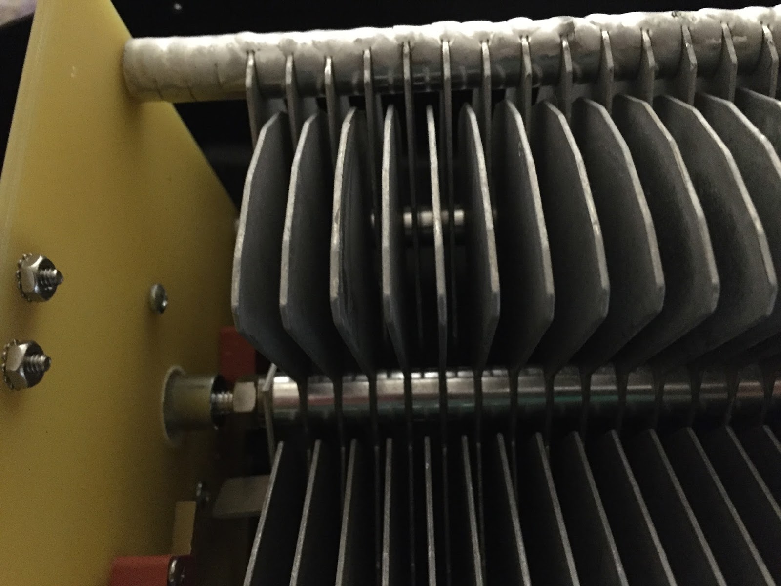
In the above picture the 3rd fin from the left was perfect centre and all others had to match.
2 2. I then inspected the PL-259 connector just to make sure it was fine and not on it’s way out due to unforeseen damage. It was ok as well.
3 3. I then brought in the MFJ 1788 antenna into the house and first had a look over of the outside case, SO-259 and the antenna loop. All seemed good this way.
4 4. It was now time to open up the plastic housing and have a look inside, I have had the antenna apart on occasion for routine maintenance so I had an idea of how things should look. There was no obvious signs of damage to any of the major parts.
5 5. It was now time to connect the coax and run the internal variable capacitor to the end of each stop via the control box.
Here is where I noticed two problems:
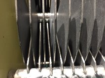
· A.The spacing between the stationary fins and rotating fins was not equal at certain points along the variable capacitor.
· B. When the capacitor was fully seated in one direction both the stationary fins and rotating fins should sit flush with each other and some on the rotating section were sitting higher.
To fix the spacing problem (which I had to do then the antenna was shipped to me) I used a screw driver to manipulate the fins to even up all the air gap between fins. To repair the fins that were not sitting flush I was able to loosen a nut on the shaft that held all the moving capacitor fins in place. I then was able to adjust the fins that were sitting to high and make them all flush.
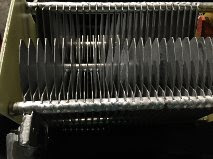

It's hard to see but from the left about 7 fins over the next five fins start to look odd, this is because these fins are not sitting flush with the other fins and they had to be adjusted so they were flush.
1 6. It was not time to cross my fingers and try the antenna (with plastic cover off) and see if this was in fact the problem. I was able to turn the antenna to 1.1:1- 1.1:4 on all bands and this was with the antenna sitting on a table in my living room. It seems the problem was fixed!
2
7. I then put the plastic cover back on and again check the SWR on all bands, I wanted to make sure nothing changed……. nothing did change and all was still good.
7. I then put the plastic cover back on and again check the SWR on all bands, I wanted to make sure nothing changed……. nothing did change and all was still good.
3 8. I then re-mounted the antenna on the tripod and covered it with my canvas patio table cover….so it does not “look” like an antenna. I then tested the SWR again…it was now 8:1!!
4 9. I then removed the canvas cover and the SWR was fine again…..seems canvas was damp do to the rain that accompanied the wind that day. I put the cover in the dryer and then back on the antenna and all was well. I am now going to purchase some waterproofing spray for the canvas to keep the antenna dry.
Below is one section of the fins that have been adjusted and are back to normal position.
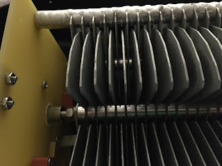
Below is one section of the fins that have been adjusted and are back to normal position.
Please support our generous sponsors who make AmateurRadio.com possible:
 Ham Radio Deluxe |
 W5SWL Electronics |
 Ham Radio Prep |
 KB3IFH QSL Cards  Hip Ham Shirts  HamRadioAuctions HamRadioAuctions Reliance Antennas Reliance Antennas Enigma Shop Enigma Shop |  morseDX  Ni4L Antennas  R&L Electronics R&L Electronics antennas.us antennas.us QRV QRV |
- Matt W1MST, Managing Editor
