 |
 ICQ Podcast Episode 227 – Operating Portable in Winter
In this episode, Martin M1MRB / W9ICQ is joined by Martin Rothwell M0SGL, Dan Romanchik KB6NU, and Ed Durrant DD5LP to discuss the latest Amateur / Ham Radio news. Colin M6BOY rounds up the news in brief, and this episode’s features: Operating Portable in Winter.
We would like to thank Ralph Kuehn KD9HNU, Bill Seward and our monthly and annual donors for keeping the podcast advert free. To donate, please visit - http://www.icqpodcast.com/donate
- Germany Access 60m
- RSGB Yearbook 2017 Error
- Pilot for Online Advanced Exams
- HamRadioDeluxe Customer Service Failure
- End of Norwegian FM
- NASA X-Ray Potential Superfast Deep Space Comms
Colin Butler, M6BOY, is the host of the ICQ Podcast, a weekly radio show about Amateur Radio. Contact him at [email protected].
Amateur Radio Weekly – Issue 139

Ham Radio Deluxe bricks user’s software after negative review
37 pages into into this forum’s discussion of HRD’s brutally inept handling of a customer complaint, the co-owner of the company wades into the fray and apologizes.
Techdirt
Amateur radio fans drop the ham-mer on HRD’s license key ‘blacklist’
Remotely killing one customer’s copy was not an isolated incident, say readers.
The Register
NPOTA contact tally tops 1 Million
Activators operating from National Park Service units across the US and Chasers around the world pushed the contact tally over its goal this week.
ARRL
EME In The ’80s
Unlike today’s widespread JT65B usage on eme, where signals can be many db into the noise and inaudible by ear, eme contacts could only be completed by actually copying signals that you could hear with your ears. This usually required big antennas and lots of power.
VE7SL
Keeping an NVIS antenna legal on 60 meters
To compute ERP, antenna gain must be relative to a half-wave dipole antenna. An NVIS antenna has a lot more gain than a dipole.
keep-nvis-legal-on-60m
A Cootie key
The “Cootie” key or “Sideswiper” is basically a double-sided straight key and has a reputation for being very hard to learn, possibly harder even than the Vibroplex Bug.
Ham Radio QRP
Using a GPS repeater antenna with the Yaesu FTM-400DR
My Yaesu FTM-400DR has had a difficult time ascertaining a GPS lock inside of my vehicle. Some others have also complained of this.
K5ACL
Video
Discovering secret “Numbers Stations”
Brian and Jason have been scanning the air waves for sstv signals for two months, but what they found was something else. An old standby from the Cold War.
The Modern Rogue
Icom-7300 spectrum scope band edge how-to
For those of you wanting to customize the band edges here’s a how-to.
K0PIR
DMR range test part 1 of 3: Baofeng DM-5R
In the series I am doing a range test of three different DMR radios from two locations. One location is 11km away and the other almost 19km away.
dmr-range-test
A diamond radio receiver
Researchers from the Harvard John A. Paulson School of Engineering and Applied Sciences have made the world’s smallest radio receiver.
Harvard John A. Paulson School of Engineering
Amateur Radio Weekly is curated by Cale Mooth K4HCK. Sign up free to receive ham radio's most relevant news, projects, technology and events by e-mail each week at http://www.hamweekly.com.
FX-9A Revisited
FX-9A Revisted
http://www.windcamp-gear.com
I was told by Frankie when it was shipped away and on the bench that there was a bad solder connection and a virtual switch issue, what-ever that might be in English.
I am happy to say that the radio came back new and working well on all bands. Receive is like many of the other videos I have watched on the internet.
I will have more updates and videos of the unit in action after the holidays.
Merry Christmas and A Happy New Year one and all….
Fred
VE3FAL
Fred Lesnick, VE3FAL, is a regular contributor to AmateurRadio.com and writes from Thunder Bay Ontario, Canada. Contact him at [email protected].
EME In The ’80s
 |
| VE7SL - my original 2m EME antenna. |
Unlike today's widespread JT65B usage on eme, where signals can be many db into the noise and inaudible by ear, eme contacts could only be completed by actually copying signals that you could hear with your ears. This usually required big antennas and lots of power.
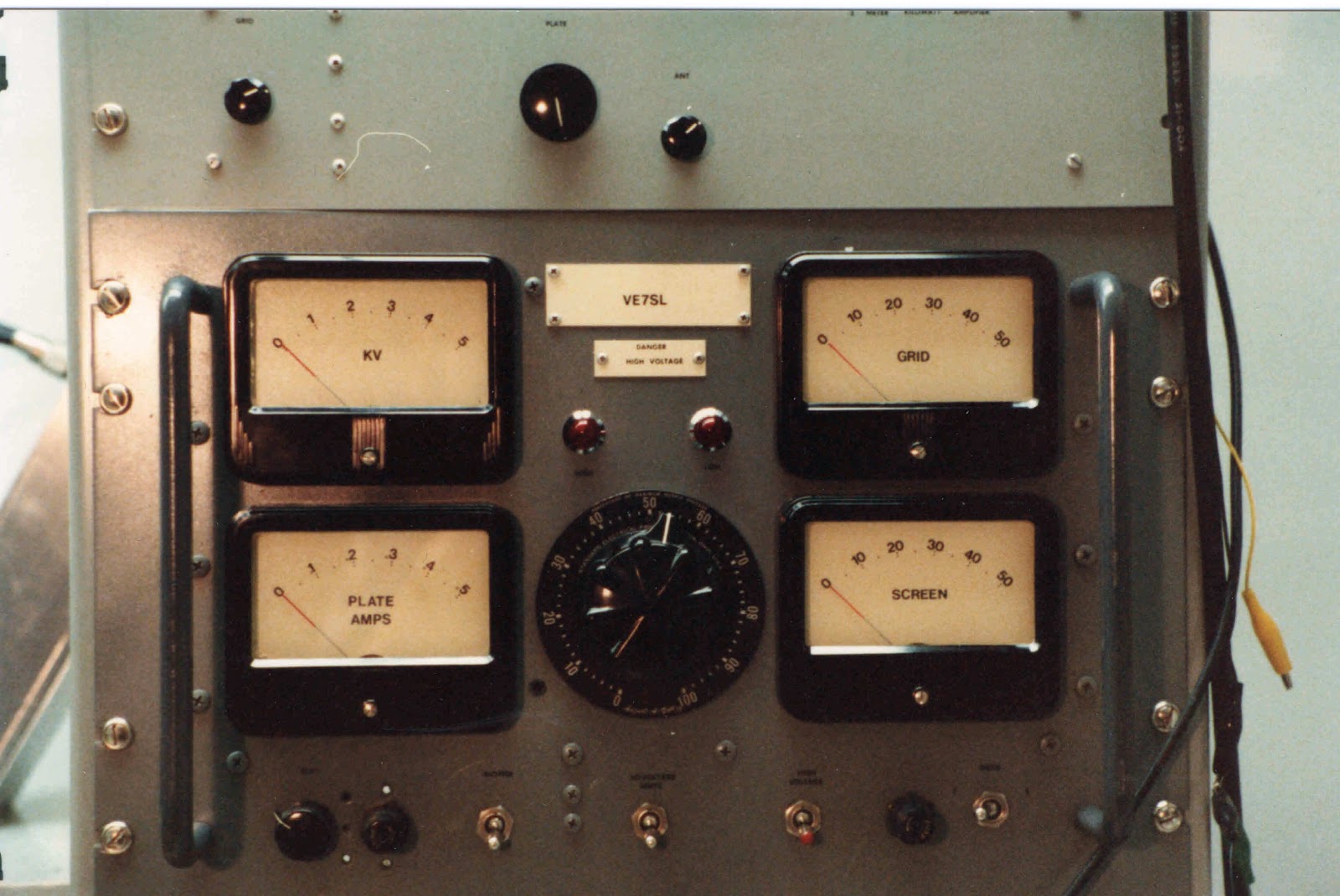
After a year and a half of evening work in my basement shop, my system was pretty much ready to go. I built a kilowatt amplifier, from the ARRL's VHF Handbook, along with its plate and screen power supplies.
 |
| 2m 'Plumbers Delight' handbook amp. |
My antennas (see above), as well as the large H-frame support, were also built in the basement and used all scrap aluminum from one of the numerous scrap yards that were in Vancouver at the time. The system consisted of sixteen separate 6 element NBS-styled yagis, all phased. Many of the two-dozen plus N connectors were bought at Boeing Surplus near Seattle, another interesting source of parts, also now long gone. Keeping water out of the phasing lines and connectors was a real challenge here in the rain forest and if one connector was not done exactly right, would create a lot of headaches.
The antenna took up a large portion of my small, 33'-wide suburban backyard. Pointing was all done by hand, using homemade scales to indicate elevation and azimuth angles, so that it could be pointed accurately even on cloud covered days and nights. A hand-cranked boat winch took care of elevation. I had a switch-box full of surplus VHF relays out at the antenna that protected my JFET preamp and also allowed me to compare sky and sun noise against a 50 ohm load.
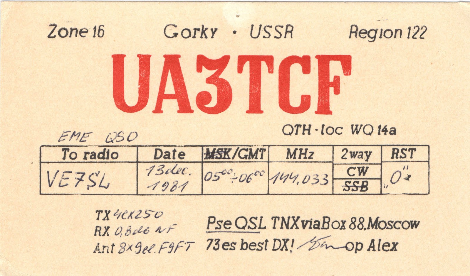
Over the course of a few years, the system was employed to work many Europeans as well as North American VEs' and Ws'. The one contact that stands out memorable for me, was with UA3TCF, east of Moscow. This was because I had to aim the array directly into my two-story house, located about 20' away! The moon was very low as well, so that not much elevation was required.
I eventually found that trying to hold down a full-time high school teaching job and running sked requests at 0300 were not very compatible! It also became a lot of work just to maintain the system properly. I had met and completed my original goals and it became time to move on.
Eventually the array was broken down into smaller sections and sold to local 2m guys, along with the amplifier ... but it was a huge learning experience for me and the fact that I survived building and playing with a 2,000 volt power supply, still scares the heck out of me!
 |
| Plate & screen supply for the 2m amp. |
 |
| The VHF rack with xvrtrs and amps 50mHz-432mHz. |
 |
| My gal Sal adorning the 2m tower on a snowy Sunday morning. |
Steve McDonald, VE7SL, is a regular contributor to AmateurRadio.com and writes from British Columbia, Canada. Contact him at [email protected].
EME In The ’80s
|
| VE7SL - my original 2m EME antenna. |
Unlike today's widespread JT65B usage on eme, where signals can be many db into the noise and inaudible by ear, eme contacts could only be completed by actually copying signals that you could hear with your ears. This usually required big antennas and lots of power.
After a year and a half of evening work in my basement shop, my system was pretty much ready to go. I built a kilowatt amplifier, from the ARRL's VHF Handbook, along with its plate and screen power supplies.
|
| 2m 'Plumbers Delight' handbook amp. |
My antennas (see above), as well as the large H-frame support, were also built in the basement and used all scrap aluminum from one of the numerous scrap yards that were in Vancouver at the time. The system consisted of sixteen separate 6 element NBS-styled yagis, all phased. Many of the two-dozen plus N connectors were bought at Boeing Surplus near Seattle, another interesting source of parts, also now long gone. Keeping water out of the phasing lines and connectors was a real challenge here in the rain forest and if one connector was not done exactly right, would create a lot of headaches.
The antenna took up a large portion of my small, 33'-wide suburban backyard. Pointing was all done by hand, using homemade scales to indicate elevation and azimuth angles, so that it could be pointed accurately even on cloud covered days and nights. A hand-cranked boat winch took care of elevation. I had a switch-box full of surplus VHF relays out at the antenna that protected my JFET preamp and also allowed me to compare sky and sun noise against a 50 ohm load.
Over the course of a few years, the system was employed to work many Europeans as well as North American VEs' and Ws'. The one contact that stands out memorable for me, was with UA3TCF, east of Moscow. This was because I had to aim the array directly into my two-story house, located about 20' away! The moon was very low as well, so that not much elevation was required.
I eventually found that trying to hold down a full-time high school teaching job and running sked requests at 0300 were not very compatible! It also became a lot of work just to maintain the system properly. I had met and completed my original goals and it became time to move on.
Eventually the array was broken down into smaller sections and sold to local 2m guys, along with the amplifier ... but it was a huge learning experience for me and the fact that I survived building and playing with a 2,000 volt power supply, still scares the heck out of me!
|
| Plate & screen supply for the 2m amp. |
|
| The VHF rack with xvrtrs and amps 50mHz-432mHz. |
|
| My gal Sal adorning the 2m tower on a snowy Sunday morning. |
Steve McDonald, VE7SL, is a regular contributor to AmateurRadio.com and writes from British Columbia, Canada. Contact him at [email protected].
LHS Episode #180: Blacklisted
 In this episode, Linux in the Ham Shack takes you a journey into sight and sound. Well, mostly sound. Topics include operating below 500kHz, new stuff in WSJT-X, an open letter from a young ham to the curmudgeons in the room, Ham Radio Deluxe being nefarious again, Ubuntu 16.10 with Budgie, a useful Debian utility, contributing to Open Source as a newbie (or oldbie) and much more.
We also send our thoughts and condolences to the young daughter, family and friends of Matthew Williams, Lord Drachenblut, KD9BWJ. He passed away much too young on December 6, 2016, after a long struggle against cancer. We miss you, brother.
73 de The LHS Crew
Russ Woodman, K5TUX, co-hosts the Linux in the Ham Shack podcast which is available for download in both MP3 and OGG audio format. Contact him at [email protected].
Radio taken a back seat
I’ve finished work for the remainder of the year and its a good time to take stock. I had a lot of plans, most of which didn’t happen as a result of some over optimism on the planning front so what went wrong. Well not much in fact when it comes to radio. I did however sneak a little progress here or there but its been barren for a few months. Before we get into new years resolutions I think its worth noting what did go on….
- I bought a MTR-5B rig which has had a few outings and a couple of QSO’s. Lovely bit of kit by the way.
- Practiced my CW a lot off air. Not so much on air.
- I acquired a TS-850 as well. Very nice
- I spent a bit of time perfecting the Raspberry Pi / RTL Dongle iGate. Pleased with that because I’m not that great with Linux.
- I am typing this on a PC loaded with Ubuntu. In an attempt to learn a bit more about Linux.
- Bought a FT-817. I really missed the old one for VHF contesting (get which section I prefer)
- Built a towbar mounted decorating pole mast. Well prototyped one at least.
- Attempted to programme an Arduino to display a load of GPS data. This is definitely in the work in progress tray.
- Did programme an Arduino to decode morse
- Wrote a piece for RSGB on the SatNOGS project we did at the club. May or may not get published
………….hang on this list is getting longer than I though it would
I suspect I’m not alone in this but looking back in the log I have not had a QSO in a few months other than on a repeater or as part of a contest. I thought that this meant I hadn’t really done much. But the reality is that, probably like quite a few, there are a more pressures on your time than you think there are. It just so happened that when this relaxed and I turned the rig on, conditions were down the khazi.
So Happy Christmas, Happy New Year and all that. Remember hams don’t just make QSO’s.
Alex Hill, G7KSE, is a regular contributor to AmateurRadio.com and writes from Cumbria, UK. Contact him at [email protected].
 Ham Radio Deluxe |
 W5SWL Electronics |
 Ham Radio Prep |
 KB3IFH QSL Cards  Hip Ham Shirts  HamRadioAuctions HamRadioAuctions Reliance Antennas Reliance Antennas Enigma Shop Enigma Shop |  morseDX  Ni4L Antennas  R&L Electronics R&L Electronics antennas.us antennas.us QRV QRV |
- Matt W1MST, Managing Editor
