 |
 No love for CW in ARES / RACES
CW - emergency communication ?
Why no love for CW?
Operating CW in Emergencies
Richard Carpenter, AA4OO, is a regular contributor to AmateurRadio.com and writes from North Carolina, USA. Contact him at [email protected].
Radio Frequency Interference From 12V-to-USB Adapters
 Many small electronic devices have switching regulators in them that can generate a bunch of Radio Frequency Interference (RFI). This is not my first encounter with RFI-spewing devices. See this article about a automotive 12V-to-USB adapter giving me trouble: This Interference Seems To Follow Me Everywhere
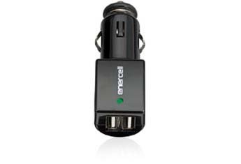
I recently bought a couple of adapters that are physically larger than the one I wrote about. I was thinking that a larger size might allow for a little more filtering and a design that does not radiate. I was half right: one of them works pretty well, the other is an RFI Bad Boy.
Take a look at this short video where I check them out.
This is an Amazon link to the adapter that works pretty well.
Enercell® 2-Port USB CLA Car Charger
73, Bob K0NR
The post Radio Frequency Interference From 12V-to-USB Adapters appeared first on The KØNR Radio Site.
Bob Witte, KØNR, is a regular contributor to AmateurRadio.com and writes from Colorado, USA. Contact him at [email protected].
ICQ Podcast Episode 255 – The Art of De-Soldering
In this episode, Colin M6BOY is joined by Martin M1MRB, Edmund Spicer M0MNG and Bill Barnes N3JIX to discuss the latest Amateur / Ham Radio news. Colin M6BOY rounds up the news in brief, and this episode’s feature is The Art of De-soldering.
We would like to thank Kevin Murphy (W8VOS) and our monthly and annual subscription donors for keeping the podcast advert free. To donate, please visit - http://www.icqpodcast.com/donate
- Hams Promote Hobby to western Virginia School
- Distracted Driving in Canada
- Are Millennials are Killing Ham Radio??
- Older Callsigns Available from Ofcom
- 10 Watt EME contact from Essex
- Amateur Radio Operator to Change on International Space Station
- Croatia gets 60m, expands 160m Access
- German Klasse K Licence Postponed
Colin Butler, M6BOY, is the host of the ICQ Podcast, a weekly radio show about Amateur Radio. Contact him at [email protected].
ALTV’s Christmas Spectacular
AmateurLogic.TV Episode 112 is now available for download.
Tommy’s battery power solution for Arduino. Peter wants to make new Hams. George builds the ultimate color ‘Heads Up’ Display. And Mike joins us for some special holiday fun.
1:28:37
George Thomas, W5JDX, is co-host of AmateurLogic.TV, an original amateur radio video program hosted by George Thomas (W5JDX), Tommy Martin (N5ZNO), Peter Berrett (VK3PB), and Emile Diodene (KE5QKR). Contact him at [email protected].
uBitx price $109 !!
It's a fast and changing world and it appears I cannot write things quick enough at the game of Amateur Radio Blogging!
Tony G4WIF has just pointed me to the price of $109 for the uBitx and a new website!
I have just read what Asharr Farhan has said on the BITX20 group. The price will rise to $129 after Christmas, due to production costs, hiring more people etc.
Of course I have just ordered mine!
Checkout here for details: http://www.hfsignals.com/index.php/ubitx/
Hope you all enjoy getting one just as much as I enjoy writing about these things.
73 Steve
Steve, G1KQH, is a regular contributor to AmateurRadio.com and writes from England. Contact him at [email protected].
uBitx multiband HF
A new HF transceiver from India is about to take to market, offering multiband operation 10 through to 80metres, with the inclusion of the WARC bands and general coverage receive.
Asharr Farhan the designer of the BITX20 and BITX40 has been working on the uBitx project for quite sometime. Demonstrations, and circuit details have been made available freely to anyone on his website Phonestack.com since early Spring 2017, for those who wished to scratch build the transceiver.
But Farhan, not resting on his recent success of producing the single band BITX40 (40m) transceiver, that introduced many to HF for a small price a point of "$59" including a recent addition of stable DDS, which he called the Raduino. VU2ESE has now put the uBitx into production, and I understand will be made available soon from his HF Signals website for purchase. (Currently the website only shows the current 40m radio for sale).
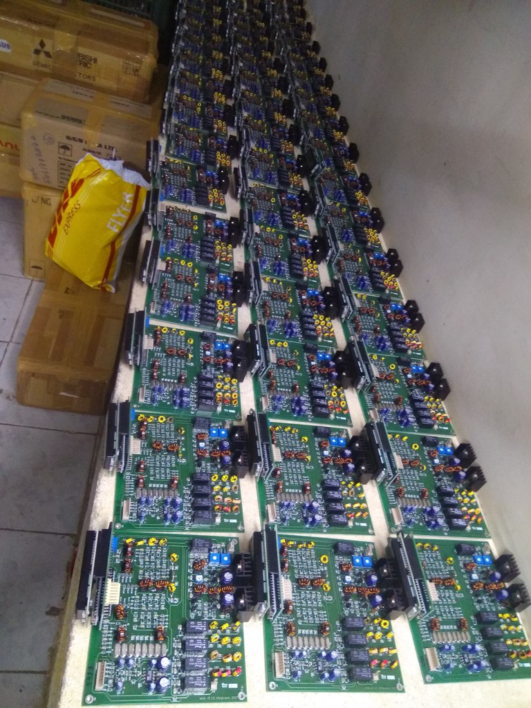
Above, a recent tested production run of uBitx transceiver boards.
The uBitx will offer CW and SSB, with 10W output from a pair of IRF510's. Arduino derived stable DDS using a Si5351 for all the local oscillators.
What you will get in the package will be a fully built and tested board. My guess is it will be sold with a similar hardware package that was included with the BITX40, which will include the wiring hardware, connectors, pots, power and BNC connectors for the antenna etc. All you will have to do is wire it up, add a speaker and a case to complete the project.
The price for the uBitx has yet to be announced? But again my guess is it will be one of it's major success stories that will take the HF world by storm and introduce many to the affordable world of HF operation. Of course, I expect it will cost more than the BITX40, but you will be getting access to most of the HF spectrum, for something until now that has proved undeliverable to those on small budgets.
Exciting times, keep watching HF Signals for further details.
Steve, G1KQH, is a regular contributor to AmateurRadio.com and writes from England. Contact him at [email protected].
Amateur Radio Weekly – Issue 184

This weekend: ARRL 10 meter contest
The objective is for Amateurs worldwide to exchange QSO information with as many stations as possible on the 10 meter band.
ARRL
WSPR Beacon Rocket is launched into near space
I launched a WSPRLite beacon on my hobby rocket at the Dec 2nd rocket launch in Samson, Alabama.
N4KGL
Review: RTL-SDR Blog Multipurpose Dipole Antenna Kit
Four antennas, two mounts, one antenna holder with cable and one more extension cable. Costs $10 on its own.
Radio for Everyone
10 watt moonbounce success
The contact was made using a Yaesu FT-857 @ 10w into a DG7YBN 70-17m 17 element yagi on a frequency of 432.063MHz
Essex Ham
My love for analog FM
C4FM & DMR Repeaters have popped up all over the nation it seems.
K5ACL
Mic amp
I connected my d104 mic to it and hooked it up to the scope and the scope pattern looks good.
awsh.org
Building a WA5VJB cheap Yagi for satellite work
I took a Baofeng UV-5R and built a WA5VJB cheap Yagi which is also used in AMSAT demos at hamfests.
galvanix
EMP protection for the Radio Amateur
What is an EMP, why should you care, and what to do about them?
Off Grid Ham
Reducing SD card writes with Raspbian
A common concern of those running applications on a Raspberry Pi is SD Card exhaustion.
K2DLS
Morse Chrome
Chrome browser extension for Morse Code
Ham Radio QRP
Video
WSJTX & FT8 the easy way with the Icom 7300
For beginners or people who don’t want the work of integrating JTAlert and/or QSORelay and a logbook. The easiest way to make FT8 contacts.
K0PIR
Pakratt PK64 on the Commodore 64 connected to raspberry pi BPQ
Testing connections to my local BBS and another BBS in the area using my commodore 64 and a PK-64 Pakatt TNC connected to a remote raspberry pi bpq over the packet modem.
YouTube
Amateur Radio Weekly is curated by Cale Mooth K4HCK. Sign up free to receive ham radio's most relevant news, projects, technology and events by e-mail each week at http://www.hamweekly.com.
 Ham Radio Deluxe |
 W5SWL Electronics |
 Ham Radio Prep |
 KB3IFH QSL Cards  Hip Ham Shirts  HamRadioAuctions HamRadioAuctions Reliance Antennas Reliance Antennas Enigma Shop Enigma Shop |  morseDX  Ni4L Antennas  R&L Electronics R&L Electronics antennas.us antennas.us QRV QRV |
- Matt W1MST, Managing Editor
