 |
 In The Loop! – Repairing a MFJ-1788
Earlier this year I spotted a posting on social media by a member of my club who had brought a MFJ-1788 second hand who was having issues with it not working. I had offered some advice on its repair and glibly offered to take it off his hands should he want to dispose of it. A few months later I got a message asking if I was still interested? I certainly was at the price he wanted.
I collect it at the club meeting a fortnight ago still with a 5ft pole still attached as a bonus! Thankfully it fitted in the car (just).
 |
| Loop as purchased, with pvc tape covering loop |
 | |
| Control Box |
I downloaded the manual and schematic from the MFJ website and I saw there were conspicuous warnings about using an 'isolated' power supply both in the manual and on the back of the controller, with ominous warnings of damage if you didn't. Most shack supplies have the negative/black pin connected to the chassis/ground.
The controller had come to me supplied with a standard fused lead, you know the ones that come to connect your ATU/SWR meter lamp to the shack supply? Mmmm.. my spider sense was tingling!
I pulled out a small double-insulated 12V plug-in supply from my collection (you can spot them as they often have a plastic earth pin) and with nothing else connected powered up the controller. The meter lamp came on and some of the LEDS briefly flickered and heard a few clicks from the internal buzzer then nothing. Pressing buttons did nothing and then I caught the unmistakable scent of burning electronics!
Opening the box up on the bench quickly spotted the source, the regular had well and truly smoked, but since nothing had been connected the short must have been in the controller itself (and it was not the dodgy wires that look like they had been victims to a wayward soldering iron)

Inspecting the rest of the board it was clear that it had been repaired (badly) once before, the two main transistors/FETs (Q1/Q5) used to control the motor clearly showed signs of being replaced (misaligned and with tell-tale scorching from an hot air gun)
a SMD diode had been swapped and one of the 'fine tune' switches had been replaced, its removal had obviously been problematic taking with it some of the through hole copper and adjacent tracks which had been lifted/damaged.


Before opening up the box I had expected to see 'through hole' components and DIL logic ICs not for it to be all surface mounted. Undaunted I went through the parts list and decided to get replacements for all the semiconductor parts not knowing at this stage what I would have to replace. Getting two of each device in some cases five or ten of each due to minimum order quantity, the staggering cost was £8 ($11) including postage!
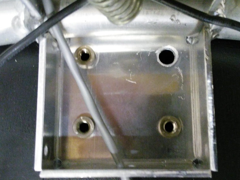
While waiting for the parts to arrive I decided to check out the actual antenna head. I removed the plastic covering and attempted to extract it from the pole..

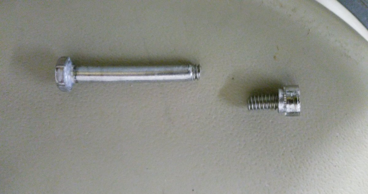
First issue I had was the mounting. One bolt had seized, the nut inserts are held in quite soft aluminium so not surprisingly the insert came out out the mounting when trying to remove it. Using grips to hold the insert the bolt still refused to turn and in the end it sheared off with very little force! Obviously quality fittings these!
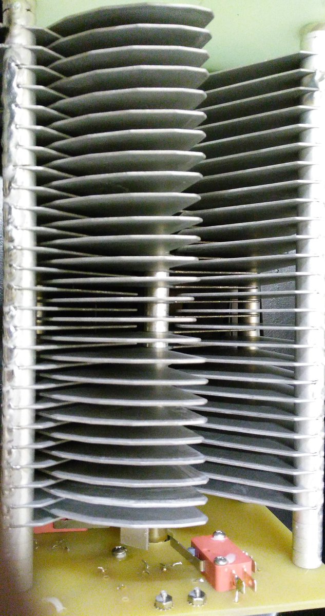
The variable capacitor was suffering a common problem due to poor quality control, the fins had gone out of alignment. Each fin is a separate assembly held on a shaft with a nut to compress them together. It is a simple fix, just realigned and tightened the bolt. The limit switches and motor connection were okay (another common problem) Applying a voltage to the coax connector the motor turned fine, reversing the voltage reversed the direction of turn, the vanes going fully in and fully out before the limit switches activated.
The components arrived prompty and so I got the hot air gun out and set about repairing the board.

I started off replacing the regulator (and the damaged power track) and Q1/Q5 and we had the flickering of life. Pressing the AUTO TUNE button the LED lit and there was 9V across the antenna connector, pressing the other AUTO TUNE button had -9V across. This is why you need an isolated power supply since it reverses the voltage to control direction. The radio doesn't see any of this voltage due to the bias-t arrangement. However if the supply shared the shack ground you would short out the supply, but the current would go via all those delicate electronics! Which is what I think had happened.
It soon became clear that most devices had suffered damage and so I ended up replacing the regulator 78L12, Q1 (SN7002 FET), Q2 (MMBT3906), Q5 (MMBT3906) all the logic ICs CMOS 4001, 4011 and 4066 and the LM324 Quad op-amp chip. I also gave the board a good clean since was covered in grime and flux residue.
Once I was happy the controller was reassembled and connected to my FT-857D on minimum power and the loop antenna propped up against the side of the shack. Success! I was able to successful tune it as per the instructions on 40m and 10m, the two extremes of operation and could here the telltale rise in receive noise as it became resonant.
I have yet to put the loop up in situ for a proper evaluation but have refurbished an old TV rotator to mount it on. I have fitted some nice new quality bolts. The black insulating tape round the loop has been removed, preferring the silver look myself.
 |
| Waiting to be put on the pole |
 |
| Shiny once again |
Assuming it does performs and will find out this weekend, I have paid a total of £65 ($90) (£50 for the initial purchase the rest for replacement parts) which is an absolute bargain as to buy new it is expensive.. very expensive!
One of the main supplier in the UK, have it on sale for £699 ($940) but this includes their engineers inspecting and rebuilding each one before shipping! (Can only be due to poor build quality control and warranty claims) the RRP seems to be around £570 ($770)
It does amaze me how much this units costs new. While the loop construction is generally good, the mounting fittings appear to be poor and the issues with the capacitor and quality control are widely reported.
The components in the controller are not expensive, the switches, meter, box are the usual MFJ fare and the design is quite old (the PCB has copyright 1998 on the silk screen) the auto-tune process requires the radio to be putting RF into a mismatched load for up to a minute and even with low power and SWR protection this isn't good for the radio PA.
Perhaps most surprising is given the risk of damage due to incorrect use is why firstly the loop isn't supplied with a power supply anyway as they only cost a pittance and secondary why their isn't any protection built in? I intend fitting a simple 100mA fuse to offer some protection should a problem occurs.
If the loop performs it may be another project to build a better controller, there are a few designs out there on the internet using Arduino and DDS devices to create auto-tuners. Has that pile of potential projects just grows taller?
73 for now.. and promise to post a bit more regularly
Andrew Garratt, MØNRD, is a regular contributor to AmateurRadio.com and writes from East Midlands, England. Contact him at [email protected].
‘CQ BR’ – It’s “Bug Roundup” Weekend!
Ever since earning my ticket as a teenager back in '63, almost all of my on-air activity has been focused on CW ... I've always loved it.
Back when I first got on the air there were very few amateurs using keyers. Most used bugs and the remainder used hand keys. It was very easy to tune across the band and identify any of the locals just by the sound of their fist ... like snowflakes, no two were the same. The same went for most stations that were very active. DX or otherwise, one could usually tell who it was, long before the call signs were sent.
So much has changed now with the almost exclusive use of electronic keyers and everyone pretty much sounds the same, which is rather unfortunate I think.
Once my interest in building vintage-style vacuum-tube transmitters evolved, my interest in bugs was reactivated and over the years I have purchased a few more.
I'll do everything I can to promote and encourage the use of CW and especially hand-generated CW. That's why I was excited, once again, to read a recent e-mail from W6SFM, posted to several lists that I read, announcing the Bug Roundup!
The Samuel F. Morse Amateur Radio Club, a Sacramento, California based CW enthusiast club wanted a special time to bring bug operators together on the air.
In the same spirit as ARRL's Straight Key Night, participants are encouraged to make simple, conversational, “chewing-the-fat” QSOs using their bug type key.
This is an opportunity to exercise, share and exhibit your personalized fist. This is NOT a contest. However, there is a very easy and quick registration form found at https://w6sfm.com/bug-roundup/.
Once you've optionally registered for the event simply Call "CQ BR" so folks know you are a Bug Roundup Participant. So lets grab that bug, clean those contacts, and let’er fly! We want to hear that “Banana Boat / Lake Erie Swing" or that commercial KPH/WCC quality fist.
Reserve the date! The event begins on Friday May 18th (00:00 UTC) and concludes Sunday May 20th (00:00 UTC)
That's 5:00 PM Friday evening until 5 PM Pacific Time Sunday (LOCAL)
For more information, to register your station, and to help assist in spotting, potentially increasing QSOs, an On-line chat window link can be found near the bottom of Bug Roundup home page located at https://w6sfm.com/bug-roundup/
We hope to hear you all on the air! 73,

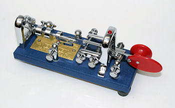
| courtesy: arrl.org |
Please see if you can squeeze-in a few hours of nice old bug-generated CW as the present digital craze is taking a big bite out of conventional CW activity it seems. Hopefully this is only temporary!
Steve McDonald, VE7SL, is a regular contributor to AmateurRadio.com and writes from British Columbia, Canada. Contact him at [email protected].
VHF SOTA: Abajo Peak (W7U/SU-014)
While on a canyon country hiking/Jeeping trip in Utah, Joyce/K0JJW and I decided to do a couple of Summits On The Air (SOTA) activations. Abajo Peak (W7U/SU-014) showed up as a suitable target, being an easy-access drive-up summit at 11,360 feet, just west of Monticello. While the forest service map shows this as a 4WD route, it turned out to be a well-maintained road that most 2WD vehicles can handle.

The map below shows the area. The only real challenge was finding B102 heading south/southwest out of Monticello. This later turns into route 0087, which swings south of another SOTA summit: South Peak (W7U/SJ-003) and up over Dickson Pass. (South Peak could be a second summit for a double activation.)

Abajo Peak is an excellent summit for VHF/UHF propagation with a good radio horizon in all directions. There is a substantial radio communications site on top which did create some local interference on 2m and 70cm. Moving a bit away from the actual summit caused the interference to mostly disappear.
I was concerned that we would not find enough activity on VHF in this rural location, so I put the word out to some of the hams in Utah and western Colorado with capable 2m SSB stations. Our equipment was a Yaesu FT-817 (all mode, 5W) driving a 3-element yagi antenna. We also had a 50W Yaesu FT-90 that can provide a bit more power out on 2m FM. And we had the usual collection of HTs.

Around noon, we started calling on 146.52 MHz and worked N7VWX in Nucla, CO (about 57 miles away). We switched over to 144.200 SSB and worked W0DSW in Cedaredge, CO (113 miles). Then we worked Bill/K0UK in Grand Junction (95 miles) on 144.200 SSB…not real strong but we made it. A bit later we came across KB7REB on 146.52 FM who said he was out hiking in a canyon and was surprised to hear anyone. We also worked KB7TRA on 146.52 (I think he was mobile east of us). We also worked W0DBB in Montrose, CO. I kept beaming to the west looking for W7DHH and I eventually heard him calling on 144.200 CW. I tried getting back to him but he was apparently not hearing me. N7KMK (same vicinity as W7DHH) came on the air and I was able to copy him on SSB. He also had trouble hearing me, but for a few seconds the signals came up a bit and we made the contact. N7KMK was my best DX for the day at 154 miles.
Four contacts are required to get the SOTA activation points and we probably would have been successful just randomly calling on 146.52 MHz FM. However, taking along the SSB transceiver and alerting the 2m weak-signal crowd certainly paid off with some longer distance QSOs. It is always a blast to be working over 100 miles on VHF QRP.
73, Bob K0NR
The post VHF SOTA: Abajo Peak (W7U/SU-014) appeared first on The KØNR Radio Site.
Bob Witte, KØNR, is a regular contributor to AmateurRadio.com and writes from Colorado, USA. Contact him at [email protected].
LHS Episode #226: Short and Sour
 Welcome to the latest episode of Linux in the Ham Shack! This is our short segment show just before Hamvention 2018. Our crowd funding campaign was successful and we thank you so very much for that. We also look forward to seeing you in Xenia. Our topics this week include the Amateur Radio Parity Act, Morse code keyboards for your Android device, CubeSat launches, Ubuntu, Ubuntu and Ubuntu. All the best and thanks for listening.
73 de The LHS Crew
Russ Woodman, K5TUX, co-hosts the Linux in the Ham Shack podcast which is available for download in both MP3 and OGG audio format. Contact him at [email protected].
The ham radio learning curve!
Here is a personal learning curve for me regarding this hobby....many times I have looked at the shack and said "there are some items here that I seem to be not using and are collecting dust" My thought is to convert those items into ham bucks by selling. Having said that here is my learning curve, there have been way to many times I have sold an item or two or three and then a short time later was in dyer need of said sold item. In some cases I have had to purchase once again the same item I sold. My learning curve or my take away is just hold onto it for a little bit longer as you may end up needing it again!
Mike Weir, VE9KK, is a regular contributor to AmateurRadio.com and writes from New Brunswick, Canada. Contact him at [email protected].
Weekly Propagation Summary – 2018 May 14 16:10 UTC
Here is this week’s space weather and geophysical report, issued 2018 May 14 0629 UTC.
Highlights of Solar and Geomagnetic Activity 07 – 13 May 2018
Solar activity was very low throughout the period and no reportable events were observed.
No proton events were observed at geosynchronous orbit.
The greater than 2 MeV electron flux at geosynchronous orbit reached very high levels on 9-11 May and high levels were obseverd throughout the remainder of the period.
Geomagnetic field activity was at quiet to active levels on 07-09, 11-12 May due to the influence of a negative polarity coronal hole/high speed solar wind stream. Quiet to unsettled levels were observed on 10 May, and conditions were quiet on 13 May.
Forecast of Solar and Geomagnetic Activity 14 May – 09 June 2018
Solar activity is expected to persist at very low levels throughout the outlook period.
No proton events are expected at geosynchronous orbit.
The greater than 2 MeV electron flux at geosynchronous orbit is expected to reach very high levels on 05-07 Jun with high levels expected on 14-26 May and 02-04, 08-09 Jun. Moderate flux levels are likely though the remainder of the outlook period.
Geomagnetic field activity is expected to reach G2 (Moderate) geomagnetic storm levels on 02 Jun with G1 (Minor) geomagnetic storms levels expected on 17 May and 01 Jun due to the influence of multiple coronal hole/high speed solar wind streams. Active conditions are expected on 18 May and 03-05 Jun and generally quiet or quiet to unsettled conditions are expected to prevail for the remainder of the outlook period.
Don’t forget to visit our live space weather and radio propagation web site, at: http://SunSpotWatch.com/
Live Aurora mapping is at http://aurora.sunspotwatch.com/
If you are on Twitter, please follow these two users: 1. https://Twitter.com/NW7US 2. https://Twitter.com/hfradiospacewx
Check out the stunning view of our Sun in action, as seen during the last five years with the Solar Dynamics Observatory (SDO): https://www.youtube.com/watch?v=zXN-MdoGM9g
= = = = =
BOOK SALE: Space Weather and Sun Science – get these from Amazon, and help us stay online!
NOTICE: When you buy this (or any item after starting with this link), you are helping us keep our SunSpotWatch.com and other resources “on the air” (up and running!). In other words, you are helping the entire community. So, check out this book:
Here is the link to Amazon: http://g.nw7us.us/fbssw-aSWSC
We’re on Facebook: http://NW7US.us/swhfr
Visit, subscribe: NW7US Radio Communications and Propagation YouTube Channel
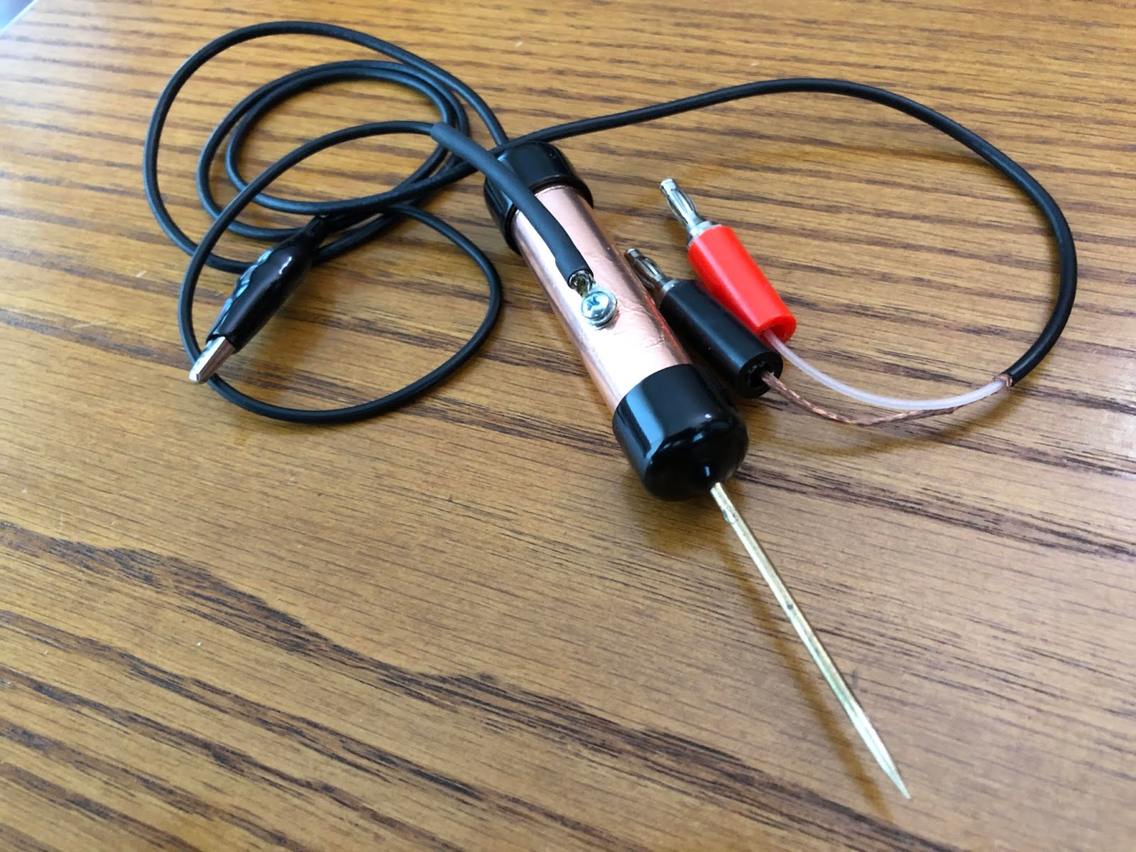
Kit building time.
 |
| Almost done |
Mike Weir, VE9KK, is a regular contributor to AmateurRadio.com and writes from New Brunswick, Canada. Contact him at [email protected].
 Ham Radio Deluxe |
 W5SWL Electronics |
 Ham Radio Prep |
 KB3IFH QSL Cards  Hip Ham Shirts  HamRadioAuctions HamRadioAuctions Reliance Antennas Reliance Antennas Enigma Shop Enigma Shop |  morseDX  Ni4L Antennas  R&L Electronics R&L Electronics antennas.us antennas.us QRV QRV |
- Matt W1MST, Managing Editor
