 |
 Hans Solves Exploding Power Transistor with Siglent’s Help! And a New Product…
Exploding power amplifier transistors! Hmm…that’s not a good start to any ham’s operating session. But it happened to Hans Summers G0UPL as he was doing development work on the firmware (version 1.03) designed to accompany his very popular QCX transceiver sold through his company, QRP-Labs. Hans, the recipient of the 2019 Homebrew Heroes Award, was doing some firmware enhancements for CAT control of the QCX (version 1.03) to drive an external amplifier when the amplifier’s power transistor …. well, see for yourself.

But what on earth caused the explosion? Here’s where a product donated to our Hero for 2019 came to the rescue. Siglent Technologies donated their SDS1202X-E oscilloscope to Hans as part of their sponsorship. He documents how he used the Siglent oscilloscope to diagnose the power spikes that led to the complete component failure in certain circumstances on his blog.
I had switched the QCX off and on again with the toggle switch on the my front panel, rather fast. There was a bright flash and a loud bang. My QCX is connected to a 0-30V 0-20A linear-regulated bench power supply, capable of supplying a lot of power. Investigation revealed that one of the IRF510 power transistors had blown up quite spectacularly. This photo shows the result. Note that the explosion did not blow the IRF510 pins off; my safe removal strategy for replacing components, is to CUT the component out then remove the pins one-by-one from the board by de-soldering them.
Hans G0UPL
Hans explains his diagnostics further, “Investigation with my nice new Siglent SDS 1203X-E oscilloscope (thanks to kind donation by Siglent, sponsors of the Homebrew Heroes award 2019), revealed the following different power-up characteristic, depending on whether the QCX is switched on by turning on the power supply, which is what I normally do, or by switching it on at the toggle switch.
The Siglent SDS 1203X-E oscilloscope has storage features where the display can be frozen by pressing the Run/Stop button at top right. So it is possible to capture an event in “human scale time” with the horizontal timebase running at something like 100ms/div or 200ms/div; then with the display frozen you can scroll it left/right using the horizontal position control, then zoom in on the feature to be investigated, using the Horizontal Zoom knob. Once the display shows the section of waveform of interest, you can use the cursors to make precise measurements of time difference, voltage difference etc. This is very useful to examine and understand features which happen too fast to be seen or captured normally. Screenshots can be captured easily by plugging in a USB flash drive and pressing the “Print” button.”


Hans gives more technical details behind his diagnosis on his blog post but the “nasty” spikes were detected through bench testing and then diagnosing the issues producing it using his new Siglent SDS 1203X-E oscilloscope. This provides a cogent illustration of how our Hero for 2019 goes about his development and testing work for his product line. Like a fine wine, it takes time to ensure that the finished product, whether it’s hardware or a firmware update like in this instance, is working as the higher level block diagrams are intended for it to.

Hans states, “My theory is, that the first PTT signal, at power-up, when coincident with all those nasty spikes at switch on (via the toggle switch), and with the PA circuit not yet settled down (all its capacitors charged up, solid state Rx/Tx switching in stable state, etc), creates the right conditions for catastrophic positive feedback in the PA to set up a huge spurious oscillation which is sufficient to self-destruct, via the explosion of one of the transistors. This does NOT occur in my normal power-up sequence via the on/off button of the power supply. Neither does it occur if I switch off with the toggle switch, wait a second, then switch on again. It only occurred when I switched on and off quickly.” The hand diagram above illustrates his theory of the self-destructing PA transistor.
This does NOT occur in my normal power-up sequence via the on/off button of the power supply. Neither does it occur if I switch off with the toggle switch, wait a second, then switch on again. It only occurred when I switched on and off quickly.
Hans G0UPL
The solution? He says it’s an easy fix. “This situation can be resolved very simply by adding a 10K resistor (value entirely uncritical) between the RX signal and +5V. When the processor pins are floating while the processor is starting up, the RX signal is therefore pulled to +5V, until the processor has started and is ready to take over the job. In this fragment of the schematic (below) the additional resistor is shown in the yellow box. I simply soldered it between IC3 pins 13 and 14 which is convenient and easy.” The diagram below illustrates the remedy shown in yellow.

Hans told me by e-mail that, “The QCX + 50W PA is now back in order and I had 9 nice QSOs this morning, with YL Elvira ZA1EM, then E74LZ, UR5MUY, IK7XJA, LZ1HDA, OM3CAZ, R7BW, EW8CP and RW3KE.” So a 10K resistor plus the workbench savvy with a new modern oscilloscope came to the rescue.
Psst…New Product!
The 50W Power Amplifier is a new product that QRP Labs has in very late development. No, it’s actually almost ready to announce with this final change. Hans wrote me today, “Yes, This 50W PA is a new product…This 50W amp is designed as a low cost single-band amplifier for the QCX (which is my flagship 5W CW transceiver http://qrp-labs.com/qcx ).”

The description of the new 50W amplifier was sent to me earlier today and should approximate what will be on the QRP Labs website (always subject to last minute changes, of course). Hans says he is finalizing the manual now and expects an official announcement in a week or so from today. So watch his website for the official announcement. The description is in Hans’ words to me by e-mail earlier today.
This 50W Amplifier includes the Low Pass Filter. It can be built for any of 40, 30 or 20m using the supplied components in the kit and therefore covers 95% of QCX owners. Any other bands would be possible too if suitable inductors and capacitors were substituted in the Low Pass Filter.

The amp kit also includes two substantial heatsinks, which are the same design of custom-made heatsink I use in my 10W Linear kit http://qrp-labs.com/linear. Each heatsink is black anodized aluminium and sized 130 x 28mm, with 25mm fins. ALL the connectors are also included in the kit.
A key feature of the amplifier kit is that it has solid state PIN diode Transmit/Receive switching, which is fast, reliable, low cost and silky smooth quiet… it enables full break-in operation (QSK) which is very important for many CW operators (hearing the band during the tiny gaps between your own dits and dahs). Perfecting the transmit/receive switching took 80% of the development time of the kit.

I have used the prototype for over 500 QSOs over the summer on 40m, working from US to New Zealand, Japan, Northern Europe to Middle East. With band conditions in the doldrums they are, or if people wish to have a sked with a friend at a particular time and location, that little extra power can be very useful! QRP has its place, QRO does too.
The custom-manufactured enclosure kit is extruded black anodized aluminium, size 130 x 63 x 25mm and the heatsinks bolt on the top. On the rear are BNC in and out connectors, DC power connector, and a jack for the PTT signal from the QCX. It is designed to match the QCX but could easily be used for other QRP CW rigs too; it may even work well in Linear operation (with the bias adjusted correctly) but this remains to be seen and tested.

Conclusion
This is the type of bench work that great designers go through, largely unbeknownst to amateur radio operators who purchase their products. Of course, there are issues that get by even the most careful workbench. But here’s a case of precisely why the corporate donors to the Homebrew Heroes Award program have chosen to participate: to give our recipient tools to help that person to do their best work on what they do in the homebrew maker space. To see more of Hans’ illustration of this episode in homebrew development, see his website for a forthcoming video.
Here’s to you, Siglent! And, to Jason Chonko who believed in the HHA program immediately and signed his company on as a sponsor. To see this 200 mhz oscilloscope in action, go to this link.
If you’d like your company’s equipment on the workbench of our next Homebrew Heroe, contact us through the HHA website. We are accepting sponsors for the 2020 HHA now and will announce a new one soon.
Frank Howell, K4FMH, is a regular contributor to AmateurRadio.com and writes from Mississippi, USA. Contact him at [email protected].
LHS Episode #314: Epic Pie

Welcome to the 314th installment of Linux in the Ham Shack. In this short-topics episode, the hosts discuss Open Source and the government, YOTA in IARU Region 2, microwave transverters, Docker, the Linux 5.5 kernel, Y2038, JS8Call and much more. Thank you for listening and have an excellent week.
73 de The LHS Crew
Russ Woodman, K5TUX, co-hosts the Linux in the Ham Shack podcast which is available for download in both MP3 and OGG audio format. Contact him at [email protected].
Weekly Propagation Summary – 2019 Dec 02 16:10 UTC
Here is this week’s space weather and geophysical report, issued 2019 Dec 02 0130 UTC.
Highlights of Solar and Geomagnetic Activity 25 November – 01 December 2019
Solar activity was very low. No sunspots were observed on the visible disk. No Earth-directed CMEs were observed in available coronagraph imagery.
No proton events were observed at geosynchronous orbit.
The greater than 2 MeV electron flux at geosynchronous orbit reached high levels on 25-28 Nov and decreased to moderate levels on 29 Nov – 01 Dec.
Geomagnetic field activity was mostly quiet. A single isolated period of unsettled was observed late on 29 Nov in response to a prolonged period of southward Bz.
Forecast of Solar and Geomagnetic Activity 02 December – 28 December 2019
Solar activity is expected to be at very low levels throughout the outlook period.
No proton events are expected at geosynchronous orbit.
The greater than 2 MeV electron flux at geosynchronous orbit is expected to range from moderate to high levels. High levels are expected to be reached on 20-25 Dec in response to CH HSS influence; moderate levels are expected for the remainder of the outlook period.
Geomagnetic field activity is expected to be at quiet to active levels. Active levels are expected on 18-19 Dec due to interaction with a positive polarity CH HSS; unsettled levels are expected on 03 Dec and 20-21 Dec; quiet levels are expected for the remainder of the outlook period.
Don’t forget to visit our live space weather and radio propagation web site, at: http://SunSpotWatch.com/
Live Aurora mapping is at http://aurora.sunspotwatch.com/
If you are on Twitter, please follow these two users: 1. https://Twitter.com/NW7US 2. https://Twitter.com/hfradiospacewx
– – – – – – – – – – – – –
Be sure to subscribe to our space weather and propagation email group, on Groups.io
https://groups.io/g/propagation-and-space-weather
Spread the word!
– – – – – – – – – – – – –
Links of interest:
+ Amazon space weather books: http://g.nw7us.us/fbssw-aSWSC
+ https://Twitter.com/NW7US
+ https://Twitter.com/hfradiospacewx
Space Weather and Ham Radio YouTube Channel News:
I am working on launching a YouTube channel overhaul, that includes series of videos about space weather, radio signal propagation, and more.
Additionally, I am working on improving the educational efforts via the email, Facebook, YouTube, Tumblr, and other activities.
You can help!
Please consider becoming a Patron of these space weather and radio communications services, beginning with the YouTube channel:
https://www.patreon.com/NW7US
The YouTube channel:
https://YouTube.com/NW7US
..
Visit, subscribe: NW7US Radio Communications and Propagation YouTube Channel
Potential Astron power supply failure solved!

One of my blog readers informed me regarding the Astron linear power supply that the outer case on the pass transistors at the rear of the supply are live with about 24 volts. These pass transistors are isolated from the case and the heat sink so the potential is there to inadvertently via a PL259 connector, USB cable or any other conducting item at the rear of your setup to short the pass transistor and destroy them. This morning I once again was searching the internet to see if anyone had devised a solution for this very issue. I came across a web page . This individual has the RS-35A power supply and came up with a great solution using a 3D printer. Now I am not at all up on the whole 3D printer thing but click on the link above (web page) and have a look at the pictures they posted. The covers look great and are very professional looking. It would look to me the plans are available to those who have access to a 3D printer to produce the guards them self. I would really like a set of these for my RS-25 but just short on the 3D printer part of things.
To my fellow bloggers have a look at the above link and do post any 3D printer info you may have as well.
As a side note below are some links to great information regarding Astron power supplies.
http://www.wb1gof.org/files/AstronPDF.pdf
http://www.repeater-builder.com/astron/pdf/astron-troubleshooting.pdf
http://www.repeater-builder.com/astron/astron-repair/astron-repair.html
https://www.ecse.rpi.edu/courses/CStudio/ham_radio_docs/astron-repair-index.htm
Mike Weir, VE9KK, is a regular contributor to AmateurRadio.com and writes from New Brunswick, Canada. Contact him at [email protected].
The Astron SS-30M power supply.

Mike Weir, VE9KK, is a regular contributor to AmateurRadio.com and writes from New Brunswick, Canada. Contact him at [email protected].
My 15 Minutes of Fame on Ham Nation
Last night, I had the pleasure of being interviewed by Amanda/K1DDN on the popular TWiT TV show Ham Nation. We discussed my book, VHF ham radio and SOTA. You can watch the whole episode here or view just my segment below.
There’s also a “photo appearance” by Stu/W0STU.
The post My 15 Minutes of Fame on Ham Nation appeared first on The KØNR Radio Site.
Bob Witte, KØNR, is a regular contributor to AmateurRadio.com and writes from Colorado, USA. Contact him at [email protected].
DXing The Utilities (Part 1)
The following blog was originally posted in 2015 but might still be of interest to anyone with a shortwave radio! Although maritime CW has all but vanished from HF, ships can still be logged and followed on digital modes, using DSC or Digital Selective Calling.
*******************************
 After building the house here on Mayne Island, in the early 90's, it was several years until I was able to set up a dedicated station. In the meantime, I limited my radio activities strictly to listening. I had a nice Icom R-71A set up in a hall closet and spent my radio-time, mostly on weekend evenings, listening to maritime CW, HF aeronautical traffic and, of course, NDBs below the broadcast band.
My HF receiving antenna consisted of three inverted-V's ... one for 160m, the second for 80m and the third for 40m ... all fed from the same coaxial line at the top of a 70' Balsam. It didn't take long to realize what an exceptional radio location I had, living right at the edge of the ocean, with dozens of miles of saltwater in most directions other than due west.

I really enjoyed following evening airline flights across both the North and South Atlantic, and in the early winter afternoons, following the commercial air-traffic all over Africa. Even though listening on 5 or 6MHz, I was amazed at how strong the signals from airliners over Africa at 30,000 feet or more could become, this far to the west. In the early mornings, directions were reversed and traffic from the far east, right into India, was fairly common. Often, small single-engine planes, usually run by various missionaries, could be heard while on the ground, taxiing at remote field locations and calling in via HF radio to request takeoff and flight-following.
Now QSL's have always been one of my top radio interests and it wasn't long before I started sending and collecting verifications for both the aircraft and the ships I was hearing ... once I had figured out how to get my reception reports to their proper destinations.
A very small portion of my 'utility' QSL collection is shown below. For the most part, it consists of PRC's or 'Prepared Reply Cards', with blank portions to be filled-in by the verification signers. Surprisingly, my return rate was around 90% and verifications were often returned with long, hand-written letters and numerous photographs ... especially from the ship RO's, as I suspect their days at sea were often quite monotonous. Even many of the military and commercial aircraft pilots would return a handwritten note along with the filled-in verification card, which I found even more surprising. It seemed that most were very surprised to hear that their radio transmissions were even making it this far and could be heard so readily.
 Some of the most interesting catches came from the Pacific, with a large variety of ships operating out of Japan. There are probably still several maritime CW stations operating in Japan. Many of these were owned and operated by commercial fishing companies and could be heard working fleet vessels throughout the Pacific on their daily CW skeds.
This interesting catch from the North Pacific was the Japanese 'fisheries research vessel' 'M/V FUJI MARU'. She was about 1200 miles NW of her CW contact, JNA in Tokyo.

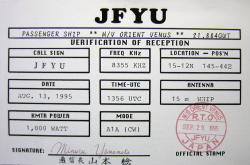
A Japanese cruise-ship, the 'M/V ORIENT VENUS' was logged early one summer morning while working JNA on 8355 KHz CW. Her position indicates she was in the Mariana Islands.


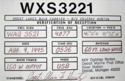
was the 'M/V Oglebay Norton', a huge bulk
carrier out of Detroit. Her 150W signal was loud and clear late one August evening while in contact with WLC, Rogers City Radio.
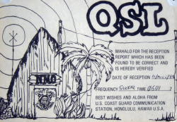
 The U.S. Coast Guard is still one of the best QSLers around.
Several of their stations will QSL with a nice printed card.
NMC (San Francisco) and NMO (Hawaii) were two
catches, regularly heard on the old 500 KHz calling
frequency.
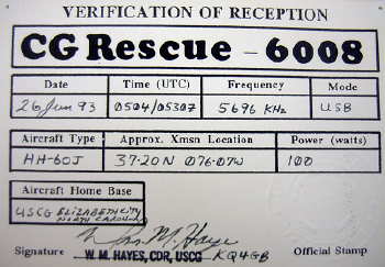
Stormy weather often provided a good chance
to catch a search and rescue mission in progress.
'Rescue 6008' was an HH-60J helo enroute from
Chesapeake Bay to Elizabeth City, North Carolina during
a midnight rescue operation.

Although not my farthest HF maritime catch,
this was one of the most surprising. 'C4PC'
was heard early one February evening on 8 MHz CW, when conditions seemed terrible. No other ships were heard on the band at the time. As I learned later, the 'M/V MAIROULI' was at anchor near Beirut, Lebanon, a distance of nearly 7,000 miles from Mayne Island.
.... cont'd
Steve McDonald, VE7SL, is a regular contributor to AmateurRadio.com and writes from British Columbia, Canada. Contact him at [email protected].
 Ham Radio Deluxe |
 W5SWL Electronics |
 Ham Radio Prep |
 KB3IFH QSL Cards  Hip Ham Shirts  HamRadioAuctions HamRadioAuctions Reliance Antennas Reliance Antennas Enigma Shop Enigma Shop |  morseDX  Ni4L Antennas  R&L Electronics R&L Electronics antennas.us antennas.us QRV QRV |
- Matt W1MST, Managing Editor
