 |
 Loopstick Magic And The CR-1 Clone
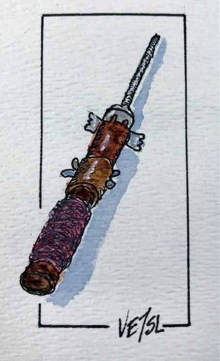 |
| BCB Ferrite Loopstick |
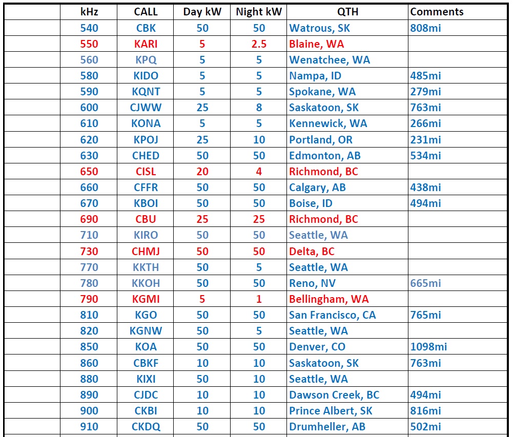
Regular blog readers may recall my two previous blogs, on the Heathkit CR-1 crystal radio receiver.
This very much sought-after radio is a well engineered ‘double-tuned’ set utilizing a series-tuned antenna tank circuit coupled to a parallel-tuned detector tank.

Both coils are wound on the same 1/4” diameter tubular form containing two ferrite slugs ... one for the antenna coil and one for the detector coil. The coils have been pre-wound and fixed on the form, about 20mm apart while the slugs have been waxed in place to set each inductance to the desired value.
 |
| courtesy: Scott's Crystal Radios |
I do wish that I'd had enough sense when I was a kid to buy myself a CR-1 as it seemed like they were dirt-cheap.

The $7.95 even included a set of headphones! Of course, $7.95 to a 12 year old was probably a lot of money, being about $70 in today’s currency!
My previous experience with homebrew DX crystal radios (ones that can hear stations other than strong locals) had taught me that they required large coils and ‘hot’ diodes. The CR-1 has neither of these yet it performed exceptionally well during the few weeks of evening tests a few months ago. I was able to log 50 stations, as described in the earlier blog ... and began to see that, just maybe, requirements may not be as rigid as I had always thought, when it comes to building DX sets!
When I discovered several ‘new-in-the bag’ broadcast band ferrite loopsticks in my junk box, I realized there might be an opportunity to allow me to make something very similar to the CR-1 circuit.
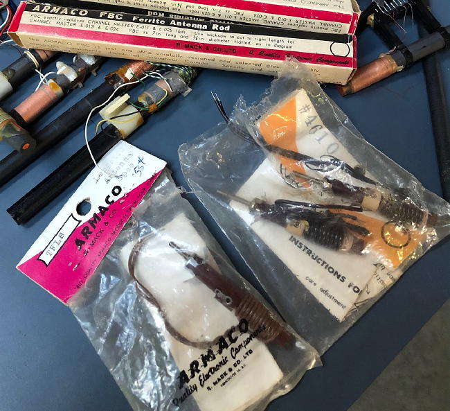
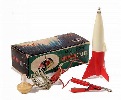
These are the same loopsticks used in the crystal ‘Rocket Radio’ of the 50s or in various transistor radios of the day.
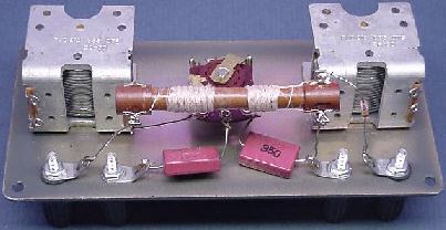
I breadboard-mounted the two loopsticks so that the distance between the antenna coil and the detector coil could be adjusted, allowing some control over coupling and selectivity ... something not available with the stationary CR-1 coils.

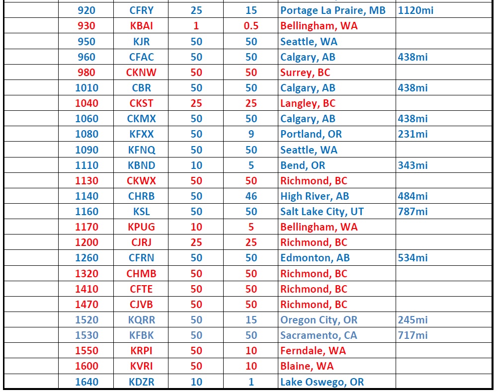
Using the same antenna, headphones and external wavetraps, proved once again the excellent performance available from a very small and simple hi-Q coil system ... a DX machine without huge coils and expensive Litz! A total of 51 stations were logged over a two-week period, one more than was heard with the CR-1 and with a few ‘almost’ heards still waiting for one of those really good propagation nights. Having the ability to adjust the coupling was very helpful and made some of the weaker stations a little easier to detect. Stations in RED are local strong signals while those in BLUE are skywave propagated DX signals:
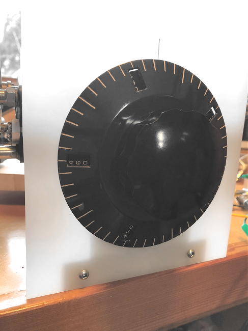
Mounting one of my old HRO 'PN' vernier dials on the main tuning capacitor provided plenty of bandspread, with each dial division corresponding to ~ 2kHz. It was very easy to locate any given frequency within the broadcast band once the dial was calibrated.
Soon after, I ran across a post by Zoltan Pap on Facebook’s ‘Crystal Set Radio Group’, describing his unique use of an old 455kHz I.F. transformer in a crystal tuner. I thought this was a rather brilliant idea and dug out an old I.F. can from the junkbox to see what it might offer.
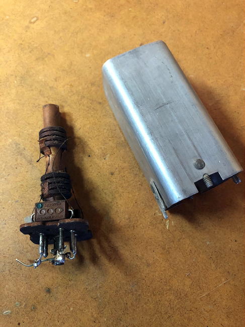
The old I.F. can had two litz-wound (10 strand) tank coils, fixed in place over two adjustable ferrite slug cores ... in reality, something very similar to the, now very difficult to find, ferrite loopsticks used above.
The two inductors measured out at ~ 700uH - 1.1mH as the slugs were tuned from one end to the other. I was aiming for something close to the inductance used in the two CR-1 tank coils ... approximately 380uH.
A sufficient number of turns were removed from both coils to yield the needed inductance and both coils on the CR-1 breadboard clone were replaced with the old I.F. can coils.

In just a few minutes of tuning through the band, it was very easy to hear and separate all 16 local stations (RED in the above log). A few hours after sunset (on a not-so-good night) yielded quick copy of KPOJ (620kHz) in Portland, Oregon (231 miles) as well as CHED (630kHz) in Edmonton, Alberta (534 miles), demonstrating that even this old 1940's I.F. can could be turned into a crystal radio DX machine!
I don't believe the 'Q' of this pair of coils is very high, compared with the smaller loopstick, as its selectivity appears to drop off above 1000kHz. I'll try separating the form into two halves so that the coupling can be adjusted. The experiment is still under way but if you want to play and can't lay your hands on the pricey loopsticks, old I.F. cans are often much easier to find and probably a lot cheaper.
Steve McDonald, VE7SL, is a regular contributor to AmateurRadio.com and writes from British Columbia, Canada. Contact him at [email protected].
Weekly Propagation Summary – 2020 Feb 10 16:10 UTC
Here is this week’s space weather and geophysical report, issued 2020 Feb 10 0203 UTC.
Highlights of Solar and Geomagnetic Activity 03 – 09 February 2020
Solar activity was very low. The visible disk remained spotless and no Earth-directed CMEs were observed in available coronagraph imagery.
No proton events were observed at geosynchronous orbit.
The greater than 2 MeV electron flux at geosynchronous orbit was between normal to high levels. High levels were reached on 08-09 Feb in response to a negative polarity CH HSS. Normal to moderate levels were observed for the remainder of the summary period.
Geomagnetic field activity ranged from quiet to active levels. Active levels were observed on 06-07 Feb in response to the onset of a negative polarity CH HSS, with wind speeds reaching a max near 650 km/s on 07 Feb. As wind speeds declined, unsettled conditions were observed on 08-09 Feb. Another isolated period of unsettled was observed on 04 Feb in response to sustained southward Bz. The remainder of the summary period was quiet.
Forecast of Solar and Geomagnetic Activity 10 February – 07 March 2020
Solar activity is expected to be at very low levels throughout the outlook period.
No proton events are expected at geosynchronous orbit.
The greater than 2 MeV electron flux at geosynchronous orbit is expected to reach high levels over 10-14 Feb and 06-07 Mar in response to multiple CH HSSs. Normal to moderate levels are expected for the remainder of the outlook period.
Geomagnetic field activity is expected to range from quiet to G1 (Minor) geomagnetic storm levels. G1 (Minor) conditions are likely on 04 Mar in response to influence form a recurrent extension of the southern polar crown coronal hole. Active levels are likely on 11 Feb, 17 Feb, 26 Feb and 05 Mar; unsettled conditions are likely 12 Feb, 14 Feb, 18 Feb, 25 Feb and 27 Feb. These geomagnetic disturbances are anticipated from multiple, recurrent CH HSSs. The remainder of the outlook period is expected to be at quiet levels.
Don’t forget to visit our live space weather and radio propagation web site, at: http://SunSpotWatch.com/
Live Aurora mapping is at http://aurora.sunspotwatch.com/
If you are on Twitter, please follow these two users: 1. https://Twitter.com/NW7US 2. https://Twitter.com/hfradiospacewx
– – – – – – – – – – – – –
Be sure to subscribe to our space weather and propagation email group, on Groups.io
https://groups.io/g/propagation-and-space-weather
Spread the word!
– – – – – – – – – – – – –
Links of interest:
+ Amazon space weather books: http://g.nw7us.us/fbssw-aSWSC
+ https://Twitter.com/NW7US
+ https://Twitter.com/hfradiospacewx
Space Weather and Ham Radio YouTube Channel News:
I am working on launching a YouTube channel overhaul, that includes series of videos about space weather, radio signal propagation, and more.
Additionally, I am working on improving the educational efforts via the email, Facebook, YouTube, Tumblr, and other activities.
You can help!
Please consider becoming a Patron of these space weather and radio communications services, beginning with the YouTube channel:
https://www.patreon.com/NW7US
The YouTube channel:
https://YouTube.com/NW7US
..
Visit, subscribe: NW7US Radio Communications and Propagation YouTube Channel
Time to spruce up the blog.

Mike Weir, VE9KK, is a regular contributor to AmateurRadio.com and writes from New Brunswick, Canada. Contact him at [email protected].
Ham College 61 – Extra Class Begins
Ham College episode 61 is now available for download.
Are you ready for Amateur Extra? Our 1st Extra Class episode. What’s on the exam?
01:03:17
George Thomas, W5JDX, is co-host of AmateurLogic.TV, an original amateur radio video program hosted by George Thomas (W5JDX), Tommy Martin (N5ZNO), Peter Berrett (VK3PB), and Emile Diodene (KE5QKR). Contact him at [email protected].
Taking steps forward.

He highlights 12 common problems and how to overcome them so please if you want to improve your code read over the document and see any issues come to light.
Of the 12 common problems, I was able to identify with 6 and they were:
1. Anticipating what is being sent. This is done when you copy with a pencil and paper and copy one letter at a time and not by the rhythm of a word. For example when you hear someone calling CQ most of us don't write down the letter C and Q. We know the rhythm of CQ and know the word. I have to learn the rhythm of CW and not writing letters. Learn the code as a language.
2. The inability to copy behind. This was a new one for me I never really had heard of it. You hear one or two letters and let them float in your head once you hear the 3rd letter you write down the first and second letters. In the past, if this happened to me I would panic as I figured I was getting behind in the copying.
3. Unable to increase my speed. I hit a plateau and become frustrated. The suggestion is to increase the code you are receiving by about 2 wpm above your plateau speed.
4. Lack of confidence. This for sure has been an issue with me I have found once a contact gets rolling I can get lost because of some of the issues mentioned above. Once this happens I just want to pass along 73 and TU and end the QSO.
5. Not able to hear complete words. This is just done with the practice of copying complete words and not each letter.
6. Writing each letter as it is heard. This for sure is an issue with me. I find as the speed increases I just get lost as I can't write things down fast enough. I have tried using a keyboard as I can type very fast but I have found that at a certain speed the letters are coming at you so fast you get lost between hearing the letter and then transposing it to the keyboard key.
The bottom line from what I have been reading is I have to learn how to put the pencil and paper away and copy in my heard with just writing down selective information. I really believe it's retraining your brain on how CW is understood. I relate it too when I first was learning to type and when I was to type "the" I would type "t" "h" "e" but now I don't even think about it.......well it's more like I think it and it appears on paper. I am not even thinking of were my fingers are going on the keyboard. I have to train my brain this way regarding morse code.
The CWops is a very popular program and spaces fill up fast and at this point in time, the class enrollment is for April/May or Sept/Oct. I am trying to see if the April/May works out for me. Until I am accepted into either time slot for the class I wanted to work on my code. So I am going to work on the above issues I have mentioned.
Mike Weir, VE9KK, is a regular contributor to AmateurRadio.com and writes from New Brunswick, Canada. Contact him at [email protected].
LHS Episode #324: The Weekender XLI

It's time once again for The Weekender. This is our bi-weekly departure into the world of amateur radio contests, open source conventions, special events, listener challenges, hedonism and just plain fun. Thanks for listening and, if you happen to get a chance, feel free to call us or e-mail and send us some feedback. Tell us how we're doing. We'd love to hear from you.
73 de The LHS Crew
Russ Woodman, K5TUX, co-hosts the Linux in the Ham Shack podcast which is available for download in both MP3 and OGG audio format. Contact him at [email protected].
Space in Morse Code
Silence is Beautiful

Proper Space (Timing)
Space between DITS and DAHS in a Character
Space between characters within a Word
Space between Words
How to Practice
When I hear break-in occur between every word I know that I'm putting in a good minimum amount of spacing
Conclusion
DE AA4OO
Richard Carpenter, AA4OO, is a regular contributor to AmateurRadio.com and writes from North Carolina, USA. Contact him at [email protected].
 Ham Radio Deluxe |
 W5SWL Electronics |
 Ham Radio Prep |
 KB3IFH QSL Cards  Hip Ham Shirts  HamRadioAuctions HamRadioAuctions Reliance Antennas Reliance Antennas Enigma Shop Enigma Shop |  morseDX  Ni4L Antennas  R&L Electronics R&L Electronics antennas.us antennas.us QRV QRV |
- Matt W1MST, Managing Editor
