 |
 Ham Radio Motorcycle Mobile [VIDEO]
A few months back I posted a story about getting a bicycle and looking up way to attach a radio to it to do some mobile work. While the summer has been busy and that project is on the side for the winter, I came across this video from KH1JH, of his Motorcycle mobile. Justin shows us how he mounted an HTX-202 from Radio Shack and is able to use it while on the road on his bike. A nice little setup if I do say so. Wish I could have a nice big hog to ride while doing 2 meters. That would be fun I bet! But I digress, here is Justin’s video. Enjoy!
73.
Rich also writes a Tech blog and posts stories every Tuesday and Thursday on Q103, Albany’s #1 Rock Station website, as well as Amateur Radio stories every Monday thru Friday on AmiZed Studios and hosts a podcast called The Kim & Rich Show with his fiance’ Kim Dunne.
Rich Gattie, KB2MOB, is a regular contributor to AmateurRadio.com and writes from New York, USA. Contact him at [email protected].
1 KW 4:1 Ruthroff (Voltage) Balun
Building baluns is just about the easiest construction project there is in ham radio. It pays to build your own, too. I’ve read reports from some disappointed hams out there who have paid good money for poor-quality baluns. The ones worth buying might cost you almost twice what you’ll pay to build your own. So I decided to build my own balun for the New Carolina Windom that I’m putting up. The total cost of materials was $40.  Balun")
The New Carolina Windom is essentially an off-center-fed (OCF) dipole. The big difference is in the balun that you use to feed the antenna. A current balun is the proper choice for an OCF dipole, since it effectively chokes common-mode current from standing on the feedline. But for a New Carolina Windom you want common-mode current on the feedline, since you deliberately use a portion of the feedline as a radiator (an additional RF choke is necessary to clamp off this common-mode current at a certain point on the feedline, but I’ll discuss that in a future post). Therefore, you use a voltage balun, not a current balun. The voltage balun allows some common-mode current to stand on the feedline.
Now, before I go any further I must warn you that I am not an electrical engineer. Baluns are a bit mysterious to me, but from the discussions I’ve read on the internet it seems I’m in good company. If you want to learn more about baluns, I recommend Jerry Sevick’s book, Understanding, Building, and Using Baluns and Ununs, available here.  This book has everything — easy-to-follow instructions for building different kinds of baluns, helpful tips from Sevick’s own experience, as well as some deep discussion of theory that should satisfy even a graduate student of electrical engineering. I followed his instructions for building a 4:1 Ruthroff (voltage) balun.
When building a balun there are several factors you must take into consideration. Do you want it to handle a full kilowatt, or are you willing to be forever limited to QRP? Now, I enjoy QRP (I love my little HW-8!), but I also want to have the option for QRO. Therefore, I chose to use not just one toroid, but two — and to use teflon-coated wire instead of the cheaper stuff you can get away with for QRP. I bought 100 feet of stranded (that’s right, stranded — it works fine!) 14 AWG silver-plated copper teflon-coated wire off of ebay for $34, shipped. That’s enough to build quite a few baluns!
When choosing the wire you’ll use in your balun, you must choose the wire size carefully. The diameter of the conductor and the distance between the center of each conductor determines the impedance of the pair you’re winding around the core. In a 4:1 balun, you want an impedance of 100 ohms. Since impedance around a core is only about 80% of that in free space, that means you want a guage and spacing that gives you 125 ohms. You can use the handy caculator for “Impedance of 2-Wire Transmission Line” at KW2P’s website, or you can figure it out yourself using this formula:
Zo = 276 * log 2(S/D)
S = distance between the centers of the two wires
D = diameter of the wire
Any unit of measurement works (inches, mm) as long as you use the same unit for both S and D.
You’ll notice that the spacing between the wires is critical. I used thin strips of strapping tape to tightly bind the wires together every couple of inches, and watched closely to make sure no gaps appeared as I wound the pair on the toroid.
Another thing you have to decide on is the permeability of the core. There’s lots of debate about this. I followed Sevick’s recommendation to use a permeability of 125 (ferrite mix 61). I purchased my two FT-240-61 cores from kitsandparts.com, stacked them, and taped them together using 3M Scotch glass-fiber strapping tape.
Now, what to put the thing in once you have it wound? The last time I built a balun, I put it in a project-box from Radio Shack. I won’t do that again — the plastic is just too thin. You want something strong enough to stand up to the stress put on the box by the eyebolts that you use to hang the balun and connect the antenna-wire to it. PVC pipe and end-caps are popular, but to house a balun this big it ends up being fairly expensive and downright heavy! I found the perfect solution at Menards for just under $7. It is a weatherproof enclosure made from PVC plastic and comes with a neoprene gasket to seal the cover to the box. I used neoprene washers for all the bolts and sealed all the entry-points (except for the binding posts and the bulkhead SO-239 coax connector) with silicone.
I spent a little time in the hardware store picking out the nuts and bolts for this thing. You want to make sure the bolts don’t work loose, so use lock-washers and lock-nuts where you can. I also used star-washers for each lug that I fastened to a bolt. Star washers have teeth in them that cut into the metal, ensuring a good connection. A fellow at the hardware store also cut me a small square of heavy plexiglass for 50 cents to use for securing the wound toroid inside the box.
When you have built your balun, you can test it by putting a pure-resistive load across the terminals and measuring the SWR across the spectrum you intend to use. For a 4:1 balun, that means a 200 ohm load (4*50=200). The SWR should be 1:1 across the spectrum. Here’s a video showing the test of the balun I built:
It looks good! I’m looking forward to using this balun. If you would like to build one of these and have any questions, ask away. I’ll give you whatever advice I can. Just remember — you’ll get what you pay for!


![]()
Todd Mitchell, NØIP, is a regular contributor to AmateurRadio.com and writes from Minnesota, USA. He can be contacted at [email protected].
A very unexpected QSO
On Friday evening I was just heading up to bed and I did my usual check on VHF/UHF to see what was happening. The FM box stopped on 145.7375. The normal station there is GB3AL but the station I could hear seemed to be in France – or at least the stations using the repeaters were. Signals were fairly weak but seemed to be fading up and down. I kept listening and the box identified; F1ZPL. A quick Google search and I was amazed. The repeater is in JN24WB – over 500 miles from me!
Tim Kirby, G4VXE, is a regular contributor to AmateurRadio.com and writes from Oxfordshire, England. Contact him at [email protected].
I am great!
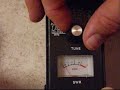
 Do you see those numbers on the display? Cool, isn’t it? That means I’m smart. Very smart. Bright and clever too. I admit I’m not too good looking, but I do have something of a genius in me. Come on guys, give me a round of applause. I did it! Finally fixed my Kenwood TS-440S. I feel like a million…..whatever currency is worth something nowadays. So, how did this sharp and brainy fellow do it? Simple: follow the 8 Volts.
After I rebuild VFO#5 last week I measured 8 Volts where I should measure 5. This bugged me for a week: where did those 8 Volts come from? So on Sunday morning I fed the family, kissed them good-bye and locked the door of my shack. With schematics, PCB layout and a DVM in hand I started out on my journey following the 8 Volts. It was a difficult track with many resistors on its path, a conductor or two and inductors to counter them. And then I arrived at a three-way junction called FET. Junction FET is known for regulating those obstinate Volts. But what do you know? Junction FET was tired beyond repair and those 8 Volts were going all three ways, where they clearly shouldn’t be. Now those of you who have travelled similar paths before (or should I just call you “old geezers”) know that you should handle junction FET with care. But until now I got away with rough-handling them. Not this time, so I quickly made amends and put in another junction with loads of TLC and some solder. And my journey ended there and then.
My thanks goes out to my family, the Yahoo TS-440S group, Mr. Liu for the components and to you, my dear readers, for putting up with me. SEE YOU ON AIR!!!
P.S. Your turn. I think I deserve at least 10 comments telling me how great I am, don’t you think?
Hans "Fong" van den Boogert, BX2ABT, is a regular contributor to AmateurRadio.com and writes from Taiwan. Contact him at [email protected].
New project– BATC DigiLite DVB-S Modulator
Note: a longer and more technically detailed version of this is at my other 'blog, which I've decided not to syndicate.
Why was I up to 3 AM last night, making me miss the Iowa QSO party today? I received a care package via “Royal Mail” on Friday from the British Amateur Television Club. It is something that was designed almost the same way (actually more clever in many respects) that I had been thinking of doing for close to 10 years.
The DigiLite is based on the “Poor Man’s DATV” by F4DAY. The project has been updated for modern computers by using a 2 channel FTDI USB serial port chip (which is the “why didn’t I think of it?” part of the design) and a closed-source (unfortunately) DSPic33 and Windows PC software to capture data from a “e-bay special” several year old Hauppage PVR-150, 250, 350 (and probably PVR-USB2) analog capture card from e-bay. (What is special about them for this project is an Conexant MPEG-2 encoder hardware chip and they are cheap!)

BATC Digilite card 3/4 way assembled at W0FMS -- topside

BATC DigiLite card 3/4 assembled at W0FMS -- bottom
The BATC’s solution of using an inexpensive PIC and the FTDI serial interface is a maybe slightly kludgy but awfully clever solution of inexpensively and simply pumping data to the QPSK modulator chip. Although there are some disadvantages to this simple interface, it is an awesome start!
The modulation used is DVB-S, which is the older digital standard used by most of the world for satellite transmissions.
I’ve been playing with LEGAL Free-To-Air satellite for many years. The majority of what is left unencrypted on C-band and Ku-band FSS satellite is receivable on an inexpensive set type box and/or PC receiver card. These receivers take in 950-2150 MHz signals as an IF (with a converter and/or a LNA in front of the IF) in Amateur use.
The main disadvantage to DVB-S for ham radio is that the modulation is pretty weak when it comes to handling multipath. Existing Yagi beams other directional antennas will mitigate this greatly in Amateur Use. See the other ‘blog for details.
THE great advantage to DVB-S for ham use– in my opinion– is that the bandwidth and data rates, even the video and audio coding the the MPEG-2 Transport streams are pretty much completely up to the link user. DVB-T in Europe and ATSC in the US is only setup for 6/8 MHz channels and IMHO there is no reason for hams to use this much bandwidth in 2011 for ATV. Neither are a good choice for low bandwidths as we NEED to have in amateur television.
Experiments by the BATC and others show that the digital signal is much more usable and stable than equivalent bandwidth analog ATV and it just gets better with reduced bit rates.
Ho, Hum? ATV? who cares? Well.. see.. it’s not really just that, is it? Data such as DVB-IP can be used for data instead. There are $20 e-bay DVB-S cards capable of receiving data as a native computer network interface via this protocol. Maybe we can restart a packet radio network up again?
So this is the start of an interesting project for me that I’ve wanted to do forever. Hopefully it will turn out well and can be revolutionary.
Fred Spinner, WØFMS, is a regular contributor to AmateurRadio.com and writes from Iowa, USA. Contact him at [email protected].
Apple iOS 5 from grrrrr to purrrr
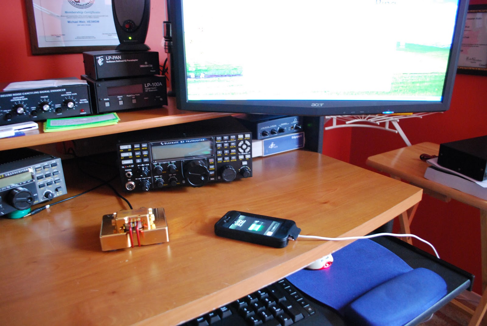 |
| Getting started |
the new things with iOS 5. Off I went to iTunes to get the update all went smooth....so I thought. I then restarted my iPhone and ALL my purchased app's were GONE.....all music......GONE and email......GONE!!!!!
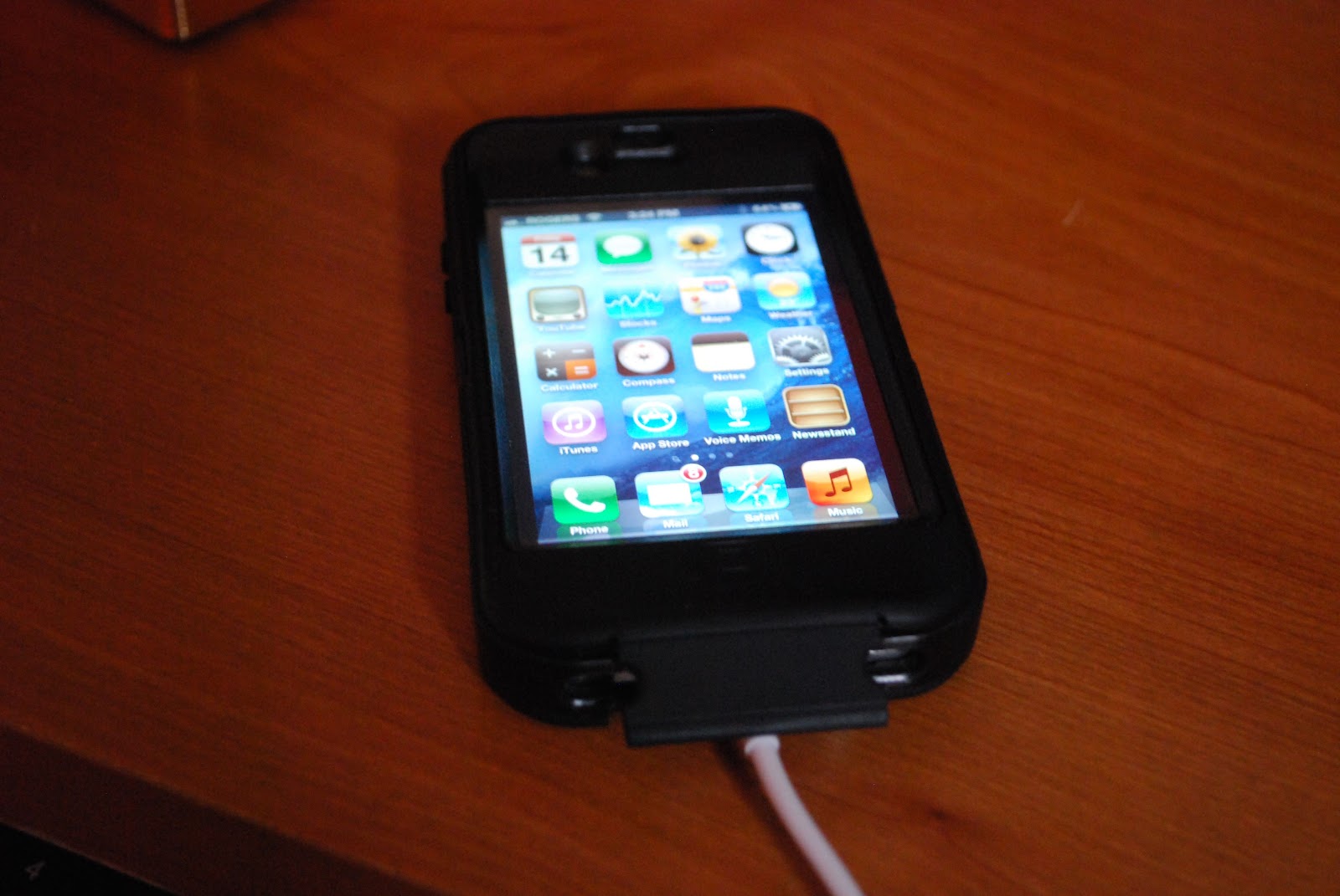 |
| All better....thanks Apple care |
Mike Weir, VE9KK, is a regular contributor to AmateurRadio.com and writes from New Brunswick, Canada. Contact him at [email protected].
Signal Graphic TI2/NA7U PE4BAS

With the help of PC4T’s tutorial I made this graphic in excel. The blue line represents my signal at Casey TI2/NA7U and the green line represents Casey’s signal at my QTH. The strange thing is that I did not receive Casey after around 01:52 UTC. But of course it could be he only listened after that time. Peak on 30m was around 02:50 UTC after that you see propagation is going up and down slowly sloping downwards. Sunset greyline at Costa Rica is at 23:20 UTC if I’m not mistaking. You see a small rise of my signal being received by Casey at that time. Casey’s signal peaked also at that time, but is difficult to see as the graphic is 3D. So I quickly made another graphic showing this. Besides WSPR on 30m I did some 10m too for 2 days, I’ve been heard in 23 DXCC now and even logged a all time new one Kazakhstan bringing me at 64 DXCC on WSPR all band.

Bas, PE4BAS, is a regular contributor to AmateurRadio.com and writes from Groningen, Netherlands. Contact him at [email protected].
 Ham Radio Deluxe |
 W5SWL Electronics |
 Ham Radio Prep |
 KB3IFH QSL Cards  Hip Ham Shirts  HamRadioAuctions HamRadioAuctions Reliance Antennas Reliance Antennas Enigma Shop Enigma Shop |  morseDX  Ni4L Antennas  R&L Electronics R&L Electronics antennas.us antennas.us QRV QRV |
- Matt W1MST, Managing Editor
