 |
 JT65A, propagation and data visualisation
When I met Dave WW2R/G4FRE back in the spring he mentioned that after you’ve played with JT65A on HF you really don’t want to do HF any other way. Having had a good weekend playing with the mode, I’m inclined to agree! Of course there are provisos – this is a mode to make bare bones contacts with minimal power or poor propagation. It’s certainly not a mode for chatting!
Having said that, I have loved having the receiver running all day hooked up to the wonderful JT65A-HF program from W6CQZ with the data being uploaded to both the Reverse Beacon Network and the PSK Reporter network
The other thing about this is that when you call CQ or work someone, you can readily see who else heard you, which is absolutely fascinating.
Over the weekend I think my signals have been heard in all continents on 28MHz running anywhere between 10 and about 50 watts (depending on conditions) to the vertical. I have had some fascinating contacts and found some interesting openings.
Mike M0PRL is interested in visualising propagation data to look for openings and he kindly put together a fascinating time lapse sequence of the stations that my JT65A receiver hears over a period of 24 hours (though I confess it’s usually switched off overnight, as you will see). Congratulations Mike, this is a really great visualisation!
Tim Kirby, G4VXE, is a regular contributor to AmateurRadio.com and writes from Oxfordshire, England. Contact him at [email protected].
Record Number of Freshmen Take Tech Exam At California University
Last estimation of the number of Amateur Operators in the US was 700,000. Now we can add another 62 to that number, as those 96 freshmen, out of 114 who took the test, passed and are now licensed Ham Operators.

Photo Courtesy of CPAC Website
The test session also set a new record for the school for how many signed up to take the test. The Electrical Engineering students from California Polytechnic State University in San Luis Obispo, California, gathered on November 4th for one of the largest exam sessions in the school’s history, sponsored by the college Amateur Radio club, Cal Poly Amateur Radio Club. The previous record of 62 students who passed their Tech license, was set in October of this year.
Cal Poly Electrical Engineering Department Chair Dr Dennis Derickson, AC0P, came up with the idea for the licensing initiative to offer the 180+ students in his class the chance to get their licenses. It took 11 VEs almost an hour to administer the test. A little extra incentive was making this test part of their mid-terms. As of Monday, November 7th, the new hams had their call signs in hand.
You can read more on this at the ARRL website. Congrats to the new Hams, and welcome to the fun!
73.
Rich also writes a Tech blog and posts stories every Tuesday and Thursday on Q103, Albany’s #1 Rock Station website, as well as Amateur Radio stories every Monday thru Friday on AmiZed Studios and hosts a podcast called The Kim & Rich Show with his fiance’ Kim Dunne
Rich Gattie, KB2MOB, is a regular contributor to AmateurRadio.com and writes from New York, USA. Contact him at [email protected].
KX3 on Ham Nation
Mike Weir, VE9KK, is a regular contributor to AmateurRadio.com and writes from New Brunswick, Canada. Contact him at [email protected].
SoftRock Ensemble RXTX IF modification
This is a pretty simple modification that converts a SoftRock Ensemble RXTX SDR RF interface board from “common-IF” (RX and TX share the same antenna port) to “split-IF” (RX and TX have separate ports). Split-IF is the standard for high-performance transverters on the 50-, (70-), 144-, 222-, and 432-MHz amateur bands.
So, I had a look at the RXTX schematics (here, here, and here) and considered the following options for where to break the RX and TX portions of radio:

The purple dots were the first option. Unfortunately, these locations on the actual printed circuit board were not easily accessible to miniature coax and this process would involve significant surgery to perform and restore the modification. The second alternative I considered was the red Xs…jumpering over the BS170 PA transistors. By this time, I was looking for a way to avoid butchering the original circuit too much. So, I elected for option three, which was to install a second T/R switch at the antenna jack (golden circle). This had at least two advantages, the first of which was being minimally invasive. The big advantage, though, is that the radio could be operated at its design output and run through a fixed or step attenuator on the TX side to the transverter. This meant that I would be assured of having a reasonably clean signal to work with if I configured the radio correctly. It also meant that I could operate the radio as designed if I simply disabled the the second T/R switch and connected the antenna to the default port.
So, here is the modification that I came up with using parts I had in my junk box. KB9YIG ships the Ensemble RXTX with a couple of spare BS170 FETs that can be used in place of the 2N7000. I just had a lot of 2N7000s and thought I’d save the BS170s in case I ever burnt one in the RXTX.

The interface to the transverter is through a DB9 connector. PTT for this transverter is +12 volts (as done with the TS-930S) on pin 6. Pin 1 is ground. Pins 2 and 3 are shorted together in the transverter cable connector to enable the modification in the SoftRock. The right portion of the schematic with the relay driver and Omron G6Y relay is based on the T/R switch from W1GHZ’s “Multiband Transverters for the Rover” that I decided not use on the microwaves when I found a cheap source of SMA coaxial relays. An I2C decoder would be great to put band data on the other pins to select a transverter (or transverter cascade for the microwaves).
The whole mess works great from a switching standpoint. When I key the PTT on Rocky or PowerSDR, it switches the TX line and keys the transverter. I’m a little ambivalent about the quality of transmitted signal that’s actually coming out. I think it’s good enough if you live in a sparsely-populated area, but I have a lot of VHF neighbors that I’d rather not upset. So, I need to do some more testing on this—a lot of it is getting the RXTX and PowerSDR configured correctly. It appears that the I/Q channels are flipped on my sound card (Audigy 2 ZS) between transmit and receive. I don’t know if that’s a wiring error in my breakout box or whether it’s normal. Spectra to come at some point…
Ethan Miller, K8GU, is a regular contributor to AmateurRadio.com and writes from Maryland, USA. Contact him at [email protected].
Eventually they will snap!

I‘ve been busy to set up to 84m horizontal loop again today. The XYL was not too happy with this. First it is a ugly thing in her garden and second we are still busy to finalize building the new bathroom and I should have spend time for that too. But then, the PA-beker contest is only this weekend, the bathroom is still there next week. It’s always a struggle to divide time between so many things especially when you got a hobby. Well, I always thought the militairy glasfiber mastparts I have to build the supporting poles of the loop antenne would be unbreakable. But the first mast snapped when I tried to get it up. Anyway, I got some spares and the next one did hold it. The loop is up again. Now, a test on 80m didn’t work out, I called several times but no one replied. I heard PA0PSA and YT2SS calling but they didn’t hear me. So I switched to 40m, a few calls to 9A6DX and we had a nice chat. Report 5/5 with 5W into the loop is not that bad. A quick modulation report guide me to another setting of the Turner +3B mike I now have connected to the Yaesu. I hope I’m ready for tomorrows PA-beker contest.
Bas, PE4BAS, is a regular contributor to AmateurRadio.com and writes from Groningen, Netherlands. Contact him at [email protected].
N1MM logger issues with the FT817
 |
| N1MM on the right VFO B… |
Well I decided to use N1MM for the upcoming PA-beker contest event. So first thing of all the preparations I have to do before I’m ready is to connect the FT817 to N1MM. That is done by the famous ZLP modem I described earlier in my blog. The problem only is that my laptop assigned the modem to virtual COM port 11. First problem, N1MM only knows 8 COM port assignments. Luckely someone had encountered that problem before and to solve this you only have to follow the N1MM help document on this subject. Once it was solved I had the FT817 communicating with N1MM. Next problem is that N1MM only reads VFO A, VFO B shows 0,00 MHz even when I switch to VFO B this does not change. I asked for a solution in some internet forums and discussed the problem with PE2KM who has a FT817 as well. Kees tried the same set up with his radio and has exactly the same issue I have. Now I’m in contact with one of the programmers I think on the N1MMlogger yahoogroup to see if we can solve this problem as apparently Ham Radio DeLuxe does read both VFOs and I can switch between them.
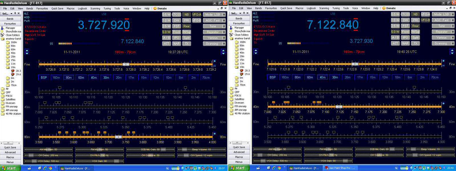 |
| HRD left VFO A, right switched to VFO B |
Bas, PE4BAS, is a regular contributor to AmateurRadio.com and writes from Groningen, Netherlands. Contact him at [email protected].
SoftRock Ensemble RXTX
A few photographs of my latest tinkering—a SoftRock Ensemble RXTX. This unit provides all of the hardware necessary to have a software-defined radio (SDR) transceiver that uses a computer soundcard for ADC and DAC. It is available here as a kit. They are kitted in batches of 20-100 every few weeks and usually sell out within 24-48 hours.

I originally had little interest in doing a full SDR transceiver (preferring receivers only) until it occurred to me that I could modify the RXTX as an IF strip for VHF/UHF transverters like many have done with the FlexRadio Systems rigs. So, I have developed a modification that is minimally invasive to the operation of the RXTX. At build time, you choose a nearly octave-wide “super band” for operation. This one was built for the 20-30 MHz band, covering the 15-, 12-, and 10-meter Amateur bands, as well as the 25-28 MHz IFs that I (will) use with present and planned transverters for the 6-, 2-, 1.25-, and 0.70-meter bands.

I’m not sure I have the enthusiasm to build another SoftRock. There are a lot of trifilar transformers to wind. The final result looks pretty good and seems to work. I’m going to put it on the spectrum analyzer soon to see how clean the output is and how I should balance the drive for the transverters. Then, I will also include a write-up of how the modifications are done. (I promise that writeup is the same place as the control circuit schematic for the 50-MHz transverter!)

Here, you can see the W1GHZ relay board for doing split-IF T/R switching. If the transverter control cable (DB-9) is disconnected, the SoftRock switches to common-RF for regular 15-/12-/10-meter operation.

Ethan Miller, K8GU, is a regular contributor to AmateurRadio.com and writes from Maryland, USA. Contact him at [email protected].
 Ham Radio Deluxe |
 W5SWL Electronics |
 Ham Radio Prep |
 KB3IFH QSL Cards  Hip Ham Shirts  HamRadioAuctions HamRadioAuctions Reliance Antennas Reliance Antennas Enigma Shop Enigma Shop |  morseDX  Ni4L Antennas  R&L Electronics R&L Electronics antennas.us antennas.us QRV QRV |
- Matt W1MST, Managing Editor
