 |
 Chris N7ICE’s first steps with the Flex-1500 SDR
If like me, you’re interested in seeing how SDR performs ‘for real’ you may well enjoy Chris, N7ICE’s HamBrief video about getting started with his new Flex-1500. As with all Chris’ podcasts and videos, it’s fun and informative in the right proportions! Take a look
Not for the first time, I am tempted to save up for one of these!
Tim Kirby, G4VXE, is a regular contributor to AmateurRadio.com and writes from Oxfordshire, England. Contact him at [email protected].
A visit to the Harwell Radio Rally, 2012
Although we had a busy weekend, I was keen to visit the Harwell Radio Rally at Didcot yesterday. After all, it is only half an hour’s drive from home and many friends were planning to be there.
I arrived just as the doors were opening – and delighted to meet Pete 2E0SQL, his Dad, Paul M3JFM and David, 2E0DAB in the queue. The queue wasn’t too long, but it was good to see plenty of people wanting to visit.
Once inside, I had a quick spin around; great to see my bosses from PW there; Rob, G3XFD and Tex, G1TEX with Phil, G3XBZ who often features in the magazine. The Harwell club had a good ‘junk’ stand and it was great to see many familiar faces there, including Des G3NNG, John G3VPW and Mike G0MJW. Mike was kind enough to mention that I hadn’t updated my blog much recently.
This is true! It’s not a lack of interest, so it’s just a temporary thing. Unfortunately Julie’s Mum has been quite ill for the last month, so we have been doing a lot of travelling back and forth to Cheltenham Hospital where she’s being looked after (happily, we hope that she is slowly, very slowly, on the mend). Add to that the fact that the recent Blogger changes mean that I can no longer update the blog from work in the lunchhour (we’re on IE7 at work…) and you can see why updates have been sporadic.
Another stall that I enjoyed was being run by my friends from the Cheltenham ARA; Derek G3NKS and Tom, G3XMM. They had some really lovely classic Drake gear with them which was from a silent key sale. I hope it found a good home – it truly deserved to. I should really have bought the enormous, but lovely NATO style morse key that was on the stand but it was a bit big and I don’t use a hand key much!
I met lots of other people whilst I was wandering around including Andrew M6BBP, who I first met when I was very first interested in amateur radio, probably over 30 years ago! Andrew is friends with Jon, G6BHS who lived three doors away from me in Cheltenham. I first realised I was living close to a radio amateur when I heard Jon and Paul G8VSH on my airband receiver! Exciting times.
So – a great hour spent with friends. Congratulations to the Harwell Club for organising such a successful event. Here’s to next year.
Oh – and I bought a copy of RadioUser magazine – not too expensive a morning!
Tim Kirby, G4VXE, is a regular contributor to AmateurRadio.com and writes from Oxfordshire, England. Contact him at [email protected].
Thanks!
Thanks to all of you here and on AmateurRadio.com who were so kind as to express condolences and kind words upon our Sadie’s passing.

This is going to take a while to get over – but life does go on.
So …… on an Amateur Radio note, the bands did not seem to be active at all today. For a few brief minutes this afternoon, I was able to get on and listen. I heard and worked EI4AA on 12 Meters and was surprised by the fact.
Bernard was pretty weak hear – 569 or there abouts, maybe a little louder – 589 on QSB peaks, maybe? As I called him, I thought to myself, “There’s no way I am going to get an answer here.” But sure enough, I did and on my first call – and I received a 559 report for my efforts. And I was very happy to receive that. Then I went down to 20 Meters and worked a station in Texas who was working the SKCC Weekend Sprint.
After that, I had to QRT as my daughter Cara (holding Sadie above), who is a member of the children’s choir at Church, was part of a free concert this afternoon. The theme was “A Night on Broadway” and the children’s choir, the adult choir, the hand bell and hand chime choirs all participated, performing various Broadway tunes. It was a very enjoyable two hour event.
Today was very windy and cold – winter has come back to New Jersey with a vengeance. Yesterday, the forecast was for 1-3″ of snow, but that forecast was a bust. We barely got a dusting – and please don’t misunderstand – I am in no way complaining!
As soon as it turns to 2/13 UTC, I am going to head downstairs to see if I can get a daily QSO or two in and then off to bed.
72 de Larry W2LJ
QRP – When you care to send the very least!
Larry Makoski, W2LJ, is a regular contributor to AmateurRadio.com and writes from New Jersey, USA. Contact him at [email protected].
Heathkit’s first amateur transmitter – Heathkit AT-1
The Heathkit AT-1 represents the commercial embodiment of the simple Master Oscillator Power Amplifier (MOPA) transmitter using a crystal controlled 6AG7 oscillator plus a 6L6 final output tube.
Although it was possible to design and build a simpler transmitter, the goals of output power and stability could become mutually exclusive when trying to operate with only one tube. For a novice class license holder of 1951 the Heathkit AT-1 represented a solid performing rig that would be relatively easy to construct and operate.
The Novice remained the primary entry license until the Morse code requirement was eliminated for Technician licenses in 1990. On HF it permitted code transmissions only, with a maximum power of 75 watts, (input to the transmitter’s final amplifier stage) on limited segments of the 80, 40 and 15 meter bands.
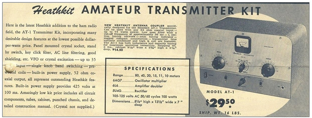 |
| For $29.50 and the loan of a few tools you could get some use out of that new novice license |
The earlier MOPA circuit from the ARRL handbook of 1941 below shows a layout remarkably similar to the circuit of the AT-1 although it is designed for plug in coils rather than the band-switching arrangement of the later Heathkit transmitter.
| MOPA transmitter using a 6L6 and an 807 as the power amplifier (ARRL Handbook 1941) |
For a little added complexity MOPA transmitters generally offered better stability of frequency and keying waveform than single tube crystal controlled or self exited rigs. The straight forward design of the AT-1 should have looked familiar to novice class hams after studying the ARRL handbook or other radio publications.
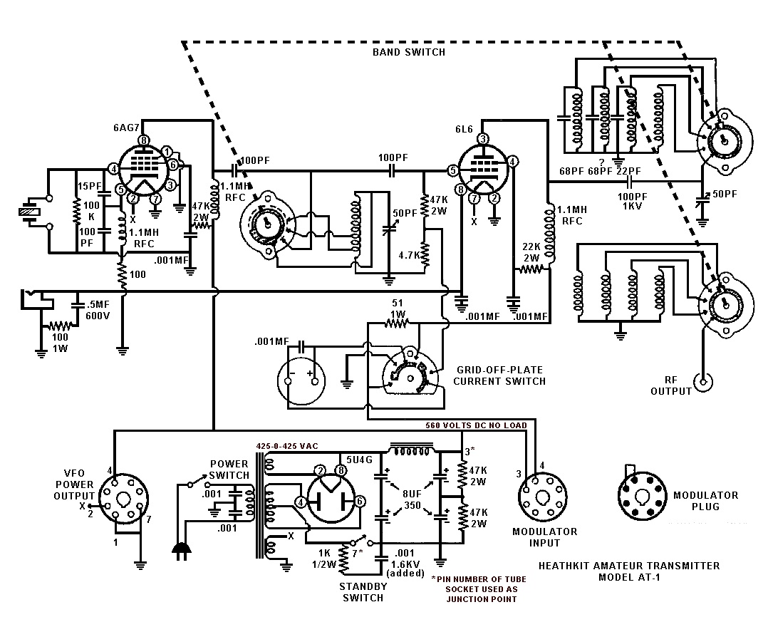 |
| Heathkit AT-1 Circuit diagram showing band-switching arrangement and link coupled output |
Once the novice had upgraded his license the AT-1 could be expanded by the addition of the Heathkit VF-1 variable frequency oscillator to allow transmission on any frequency within the allowed band.
 |
| The Heathkit VF-1 Variable Frequency Oscillator |
The VF-1 covered 160-80-40-20-15-11-10 meters and used an OA2 voltage regulator tube to provide a stable voltage for the oscillator. Ceramic coil forms, solid construction and high quality components were used to help increase stability.
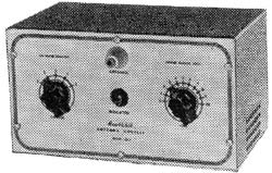 |
| The Heathkit AC-1 Antenna Coupler. Designed to attach to a single wire by the insulated post on the front panel. |
 |
| Heathkit AC-1 Antenna Coupler circuit diagram |
Although Heathkit did not produce a AM modulator for the AC-1 there is provision for modulator connection on the rear panel. The earlier ARRL manuals have several suitable circuits for modulators that would work with the AC-1. Most functioned by driving a modulation transformer with the output from an audio power amplifier. The secondary of the modulation transformer would be carrying the DC plate supply for the power amplifier tube plus or minus the instantaneous voltage of the audio waveform. By changing the plate voltage to the final amplifier tube the radio frequency output would be controlled by the amplified audio frequency resulting in amplitude modulation.
Owen Morgan, KF5CZO, is a regular contributor to AmateurRadio.com and writes from Texas, USA. Contact him at [email protected].
So what’s been going on………
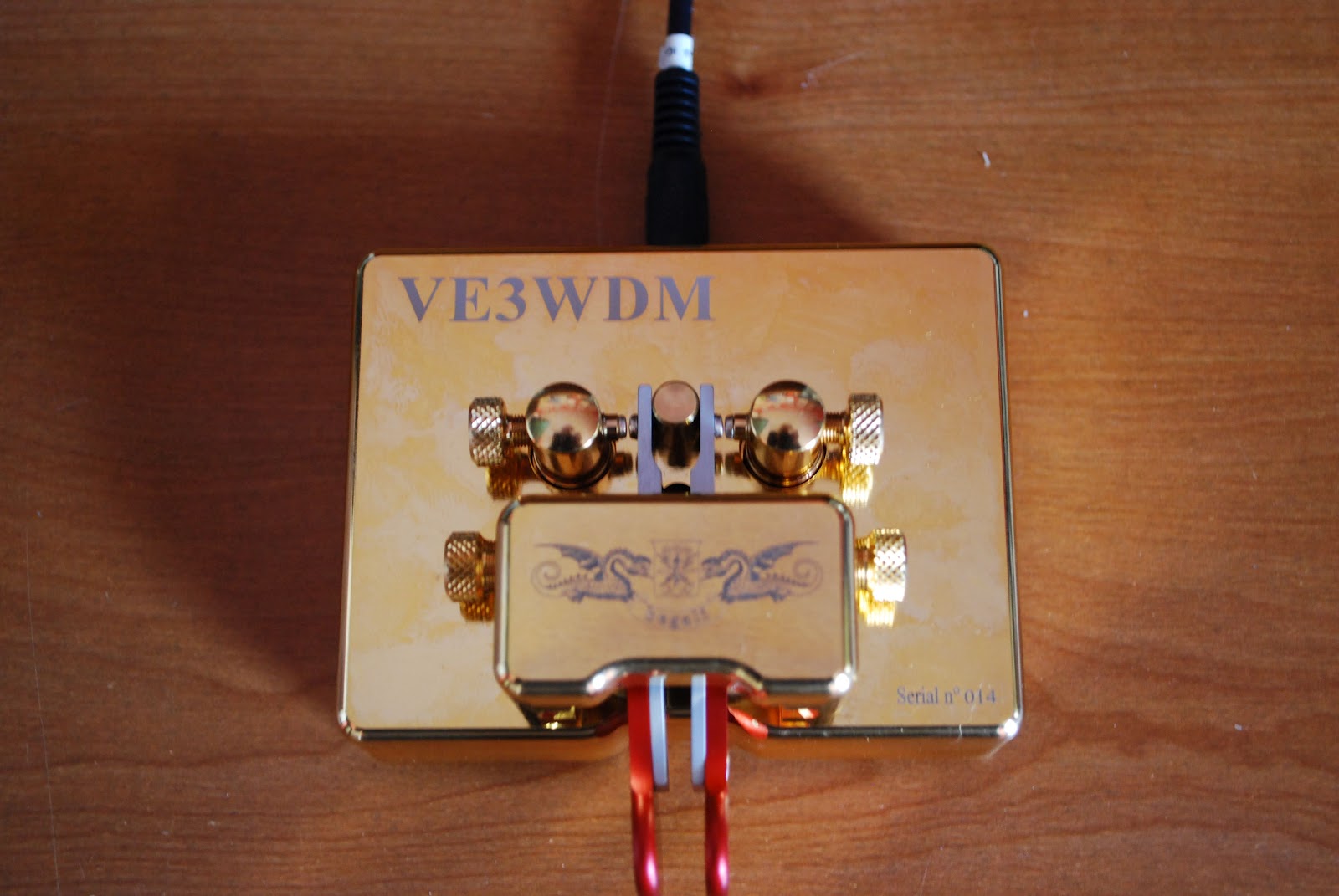 |
| The repaired key ready for action |
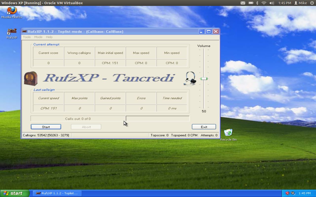 |
| RufzXP happy again |
took the jump and downloaded Virtualbox onto my Ubuntu laptop and installed WinXP. Virtualbox is a great program that allows you to run other operating systems within a "virtual computer" it creates. I now have Windows XP running on my machine and was able to install Netframe 2.0 and RufzXP...all are getting along just fine now.
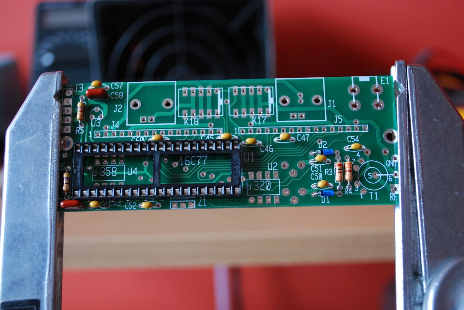 |
| The KAT2 which also has a "cat" hair |
Mike Weir, VE9KK, is a regular contributor to AmateurRadio.com and writes from New Brunswick, Canada. Contact him at [email protected].
Propeller crash
Yesterday I had another of those days that nearly made me decide to hang up my soldering iron for good. Some readers may have spotted the despondent blog post I made before I deleted it.
I assembled the Propeller LCD UI module. It went together easily and I had no trouble with the soldering using a magnifying lens (a strong pair of clip-on reading glasses clipped on to my normal reading spectacles) and resting my soldering hand on the desk to stop the shakes. But Murphy was not going to let me get off that easily.
Preparing to test the UI board I realized that I had skipped a page of the instructions and had not soldered a connector to the LCD daughter board. I thought that a connector for the main board (a male 8 x 2 box header) had been omitted from the kit so I had installed one of my own. When I picked up the daughter board I saw the two rows of 8 holes and without thinking installed the 8 x 2 plain header that came with the kit. Also male. When I realized my mistake bad words were said. In all my years of kit building I have never before done anything quite so stupid.
I recalled Don Wilhelm W3FPR’s advice to K2 builders who install multi-pin connectors on the wrong side of the board to sacrifice the connector and not try to remove it intact. This I eventually did with Olga’s help. She suggested I place the soldering iron body along the row of soldered joints to melt all of them so the connector would fall out. That didn’t work, but it did soften the plastic part of the connector allowing it to be pulled away. I could then remove each pin one at a time and clean up the through holes using one of Olga’s sewing needles. Finally I was able to install the four 1 x 4 female headers that had presumably been supplied with the kit as a replacement for an 8 x 2 female that was really needed.
After all that stress (both to me and the board) I was relieved that when I plugged it in to the Propeller board and ran the demo program the UI module worked. But my happiness was short-lived. After I tried some modifications to the program I found that it seeemed to be crashing. The program would start at switch-on but would eventually hand up and not respond to the buttons. Sometimes garbage appeared on the LCD. The time before this happened got shorter with each attempt until sometimes the Propeller wouldn’t even respond to the reset button. I restored the original program in case my changes were to blame, but the device was still crashing.
Next I re-heated all the solder joints I had made, though they all looked OK. On reassembly the Propeller still crashed. Thoroughly despondent by this point I typed a post describing what happened in the hope that someone would offer to come to my rescue (thanks to those who did.)
After a rest it occurred to me that I had crashed the Propeller by dropping the board a centimetre or so on to the desk. There was probably still a bad connection somewhere. I re-soldered all the joints, including all the ones on the main Propeller board. That had been ready assembled. I guess that the manufacturer had used lead-free solder because I couldn’t melt the joints until I applied a bit of my own leaded solder to each one. Then all the joints looked nice and shiny.
After that treatment everything worked and up until now, cross fingers and touch wood, has continued to do so. So it seems that a poor soldered joint in the manufactured board was the cause of my problem! Thank you, Murphy, but I don’t need your help. We do this for fun, do we?
Julian Moss, G4ILO, is a regular contributor to AmateurRadio.com and writes from Cumbria, England. Contact him at [email protected].
WD40
Two days ago we still had 10 degrees Celsius and rain. Sunday saw 24 degrees and sun. So what better to do than cleaning the Spiderbeam pole. WD40 sure made it shine again.

Hans "Fong" van den Boogert, BX2ABT, is a regular contributor to AmateurRadio.com and writes from Taiwan. Contact him at [email protected].
 Ham Radio Deluxe |
 W5SWL Electronics |
 Ham Radio Prep |
 KB3IFH QSL Cards  Hip Ham Shirts  HamRadioAuctions HamRadioAuctions Reliance Antennas Reliance Antennas Enigma Shop Enigma Shop |  morseDX  Ni4L Antennas  R&L Electronics R&L Electronics antennas.us antennas.us QRV QRV |
- Matt W1MST, Managing Editor
