 |
 Programming the Baofeng UV-5RA
A few days ago, I was chatting to Andy G6REG and he mentioned that he needed a lead to help program his UV-5. Rather than have him wait to order one from Hong Kong, I suggested that I send him my lead so that he could could get started straight away.
Life’s never quite that simple though. The lead arrived with Andy and he installed the drivers but on running up the Baofeng programming software, it wouldn’t talk to the radio.
At that stage we thought it was a driver issue on Andy’s laptop. Andy decided to order a lead and driver anyway and return the lead to me. On a whim, he suggested that he send me one of the radios to see if I could program it.
When I opened the packet, I immediately noticed that Andy’s UV-5 was different to mine – it’s a UV-5RA. I made sure that the programming lead was working on my laptop and then ran up the software and downloaded the memories from my UV-5. So far so good!
Then I tried to write the memories back to Andy’s UV-5. No! Communication fault. It was then that I realised that the Baofeng programming software that I had used to program my UV-5 would not work with the later model!
A quick Google around revealed that this was indeed the problem and that others had got around it by using the CHIRP programming software. It seems that the ‘stable build’ version of CHIRP (0.2.3) does not support the UV-5, however, the latest daily build does. This I was able to download here
I also found some interesting notes about programming the UV-5 with Chirp
CHIRP installed readily and I was quickly able to download an ‘image’ of my UV-5R and save it. I then tried to write it back to the UV-5RA. The first time I did it, an error occurred, however, I remembered I had seen this on a first communication before and persisted.
Yes! Second time through and CHIRP was able to write the memories back to Andy’s UV-5RA.
So there we have it. Most likely, Andy didn’t have a driver issue on his laptop. At that stage we didn’t know that the basic Baofeng UV-5 software didn’t work with the new style rig, so I suspect that had he installed CHIRP it would have probably worked fine.
Tim Kirby, G4VXE, is a regular contributor to AmateurRadio.com and writes from Oxfordshire, England. Contact him at [email protected].
50 MHz VUCC Via Logbook of the World
Bob Witte, KØNR, is a regular contributor to AmateurRadio.com and writes from Colorado, USA. Contact him at [email protected].
The 2012 log book……….
| 2012 | 100 | 500 | CW: 100.00% Phone: 0.00% Data: 0.00% | |
| 2011 | 49 | 258 | CW: 100.00% Phone: 0.00% Data: 0.00% | |
| 2010 | 25 | 170 | CW: 100.00% Phone: 0.00% Data: 0.00% | |
| 2009 | 10 | 192 | CW: 19.27% Phone: 0.00% Data: 80.73% | |
| 2008 | 45 | 495 | CW: 36.57% Phone: 0.00% Data: 63.43% |
My contacts for the year were 500, I thought it was a lot more but there were times I would forget to log contacts. BUT I almost doubled my contact total from the year before of 258. Seems I have to get away from the soldering iron and on the rig more!!
I was able to make it into 23 CQ zones
Some of my highlight contacts were Gibraltar, Iceland, Kazakhstan, Jordan and ST. Pierre & Miquelo.
Finally I was able to better my 1,000 miles per watt distance to 45,869 miles per watt with a QRPp contact to HA8JV with 100mWs of power.
Mike Weir, VE9KK, is a regular contributor to AmateurRadio.com and writes from New Brunswick, Canada. Contact him at [email protected].
An interesting discovery about sound cards
 |
| CheckSR result at 48kHz with internal sound card |
I have several radios connected to my shack PC. For the audio interfacing I have several sound cards or sound devices since most of them are not internal cards but use USB ports. I wanted to make sure the rig I mostly use for digimodes used the best sound card I had so I thought I would do some tests.
Some people believe it’s better to use a high end sound card for radio work. I don’t think there is any benefit for HF use as the noise level will be much higher than even the poorest sound card. There is no advantage to using a device capable of more than 48kHz sample rate unless you are using SDR software and need the extra bandwidth.
The one factor that can really made a difference is the accuracy of the sample rate. Most digimode software uses either 11025Hz or 48000Hz. There is no theoretical advantage to using a faster than 11025Hz rate for terrestrial digimodes. A 48kHz sample rate should not give any benefit and will need more CPU cycles to transfer and process the extra samples.
Sample rate accuracy is important because it affects both the pitch of playback and the data rate. It’s like playing an LP at the wrong speed. If you play a 33rpm LP at 45rpm the music is played at a higher pitch and a faster tempo. If played at a lower speed the sound is lower pitched and slower. This is analogous to what happens if the sample rate of your sound card is not exactly what your digimode software expects it to be.
I tested a number of sound devices using CheckSR.exe. This is a utility that is distributed with the MixW digimode software, but you can probably find it on its own if you Google it. To use it you simply select sound devices for input and output and set the sample rate you wish to test. You then run it until the measured sample rate settles on a stable figure.
I tested the Realtek sound cards built into my shack PC (HP) and a laptop (Dell) using both 11025Hz and 48000Hz sample rates. Both sound cards were as close to the specified sample rate as makes no difference.
 |
| CheckSR result at 11025Hz with USB device |
I then tested a number of USB devices ranging from a $1 audio ‘dongle’ to a $10 model with surround sound and SP-DIF inputs and outputs. The drivers for these devices had names like ‘USB sound device’, ‘Generic USB sound device’ and ‘USB headphone set’. These devices were also close to spot-on at 48000Hz.
But at 11025Hz every single USB device had a measured sample rate of 11100Hz – 1% faster than specified. This would make a 1kHz audio tone play at 1010Hz, whilst a 1200baud APRS packet would be transmitted at a rate of 1212baud. This error is more than enough to prevent decoding of an FSK packet signal. Other digimodes are also subject to sample rate errors. If you have ever seen a PSK or Olivia signal that is strong and clear yet decodes as garbage, an incorrect sample rate (at one end or the other) is the reason.
I was surprised that the sample rate error at 11025Hz was consistent across all USB device samples. This suggests to me that the measured rate of 11100Hz is a factor of the drivers for these devices which may not run at the speed you select but instead resample down from a native speed of 48kHz. It would be interesting to see the results of running CheckSR on some branded USB devices or SignaLink USB interfaces that have their own drivers.
I ran some tests on USB devices at other sample rates. There was no consistency. At 8000Hz the measured rate was fast by a significant amount, but 16000Hz it was slower.
The results suggest that USB audio devices are only as good as internal sound cards if a 48000Hz sample rate is used. The use of lower sample rates with USB devices should be avoided.
Julian Moss, G4ILO, is a regular contributor to AmateurRadio.com and writes from Cumbria, England. Contact him at [email protected].
A virtual impossibility
If you have been following my attempts to set up beacon monitoring using a software defined radio (SDR) then you may remember that I had found that Omni-Rig, the radio control software used by Faros, the beacon monitoring software, would not talk to the virtual serial port created using VSPE in order to control the SDR-Radio software. I thought there was a problem with SDR-Radio’s emulation of the Kenwood control protocol. In fact, that turned out not to be the case at all.
A reader asked if I had tried DDUtil, a.k.a. VSP_Manager, a program by K5FR so I got hold of a copy. The instructions made my hair stand on end as it seemed very complicated. But I managed to set up a virtual port pair between COM8, the control port that SDR-Radio was using, and COM9 which would be used by Faros. VSP_Manager threw up a few error boxes but it still seemed to have done what I asked. I then tried setting up Omni-Rig. The first attempt failed, but I decided to try again as the help files actually showed VSP Manager being used with Omni-Rig and sure enough I had Faros changing bands and frequencies of SDR-Radio.
My joy was boundless, but not for long. I fell at the next hurdle which was using a Virtual Audio Cable (VAC) to pipe the audio from SDR-Radio into Faros. VAC also looked complicated to set up, but what I was attempting to do was the simplest application of it. I created a virtual audio port and set the SDR-Radio output to use it. As soon as I connected this to Faros’ input Faros began spitting out “divide by zero” message boxes so fast that I couldn’t close them quick enough to get back to the Settings window to change it back again. Another brick wall.
A separate issue was that of creating a serial port splitter to allow two applications to connect to physical port COM3 used by my Elecraft K3. VSPE could do that easily, but yesterday I discovered that WSPR would not talk to the virtual port created by VSPE. However, VSP_Manager does not seem to enable you to split a real port into a pair of virtual ones anyway, so I did not pursue this avenue any further.
If you are confused trying to follow all this you are not the only one! I have abandoned the idea of using an SDR for beacon monitoring and am breathing a sigh of relief that I never decided to go down the road of buying a Flex or other software defined transceiver. SDR will never catch on until connecting the software defined radio to logging programs or digimode software becomes as simple as plugging in a real cable.
Julian Moss, G4ILO, is a regular contributor to AmateurRadio.com and writes from Cumbria, England. Contact him at [email protected].
handiham – ham radio for people with disabilities 2013-01-08 20:41:00
Pat Tice, WA0TDA, is the manager of HANDI-HAM and a regular contributor to AmateurRadio.com. Contact him at [email protected].
GSM phone power control and signalling
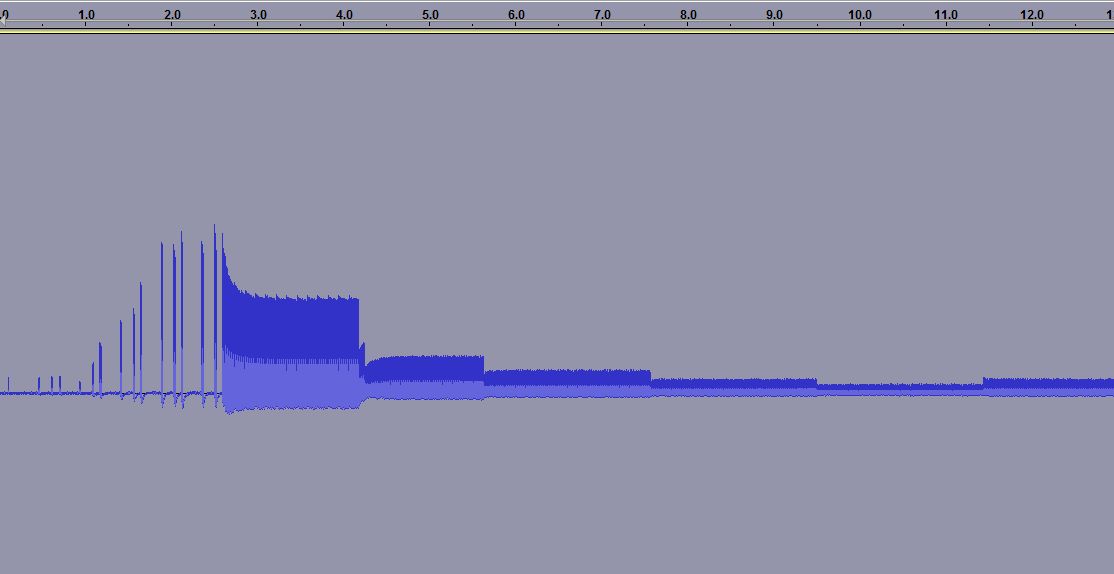
When you measure the energy out of a GSM cell phone at the moment of initiating a call, you get the picture to the right. It shows the first 15 seconds.
For the first 3.5 seconds there is the signalling between the phone and the base station. Then the connection is established, but after some time (at 4.2, 5.6, 7.5 and 9.5 seconds) one can see how the phone turns the power down, according to the commands it gets from the base station.
 The first example was for the case of a strong received signal, all bars are shown in the signal strength meter. The reduction in power, preservers battery life and as a side effect the user is exposed to a smaller amount of radiation. Interestingly, one can see that after a while there is a small adjustment of the power and it is turned up a bit (at 11.5 seconds).
 In other cases one can see a situation which follows the same pattern in time, except that the power stays at a high value. This second recording was done in my basement where GSM coverage is much poorer. Here the phone’s signal level indicator hardly shows any signal.
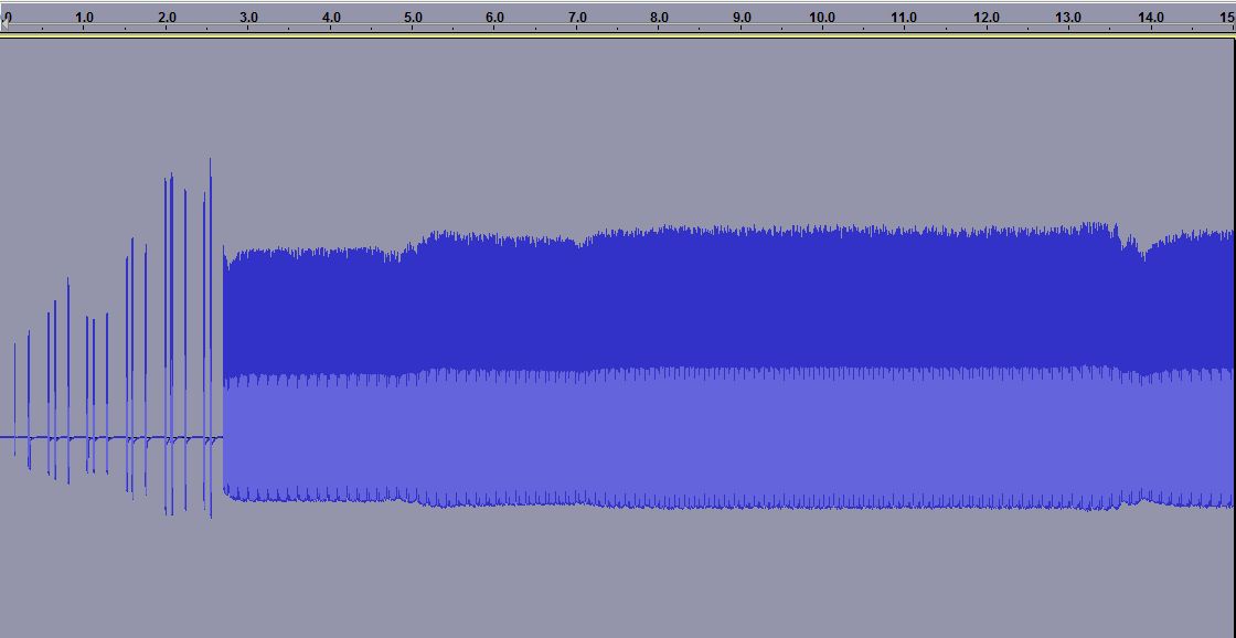

The third plot is a zoom of the previous one. Here one can see how the phone only transmits 1/8 of the time as it shares the channel with 7 other phones in a time multiplex. It is allowed to transmit every 4.6 ms and this is the reason why one often can hear a buzzing sound at 1/4.6 ms = 217 Hz in equipment which is placed close to a phone.
One also sees another frame structure, as the phone transmits 25 bursts and then breaks for one burst before continuing. Every transmission consists of 150 bits, but that is not possible to resolve with the simple setup that was used here.
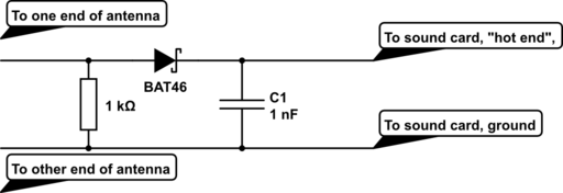
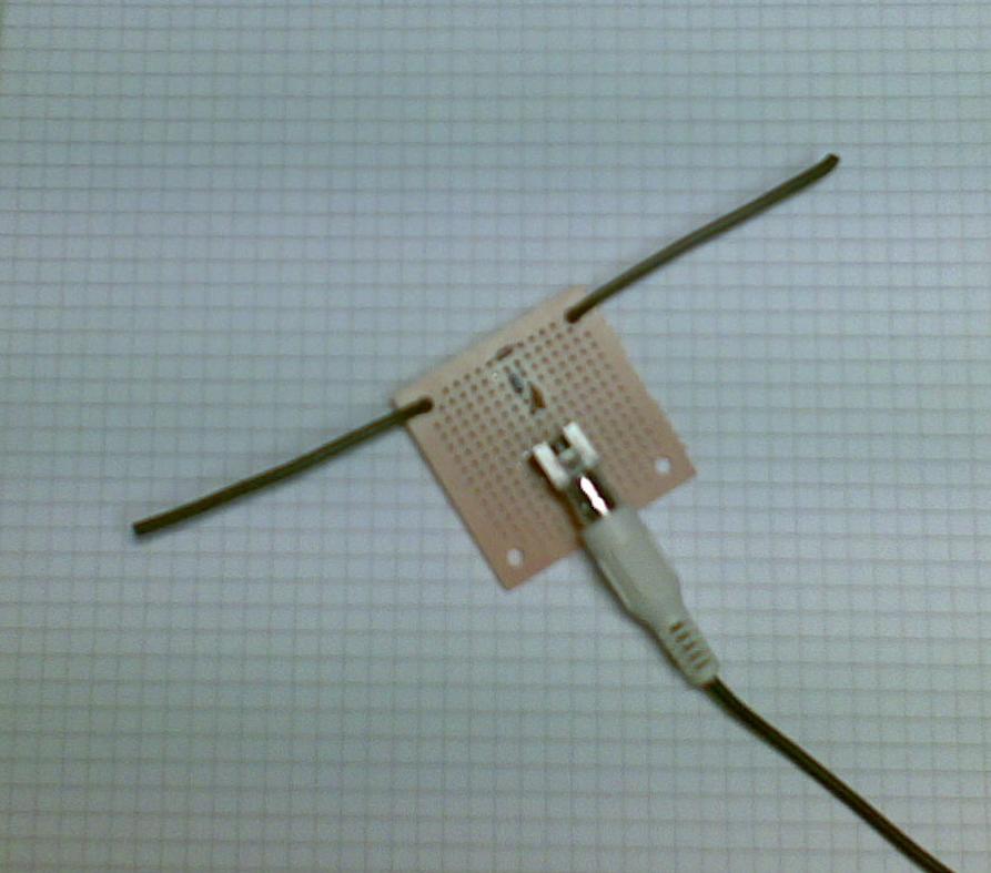 The equipment was a dipole antenna and a simple diode detector:
- A half wave dipole antenna for 950 MHz has a length of 0.5*3*108/950*106 = 15.8 cm, thus the antenna is about 2 x 8 cm (probably not very critical). The antenna was made from stiff self-supported wires.
- There is a resistor of R=1 kohm across the antenna and then a Shottky diode which acts as a detector (A Shottky diode which handles higher than 1 GHz is needed and BAT46 was used here), and finally a 1000 pF capacitor as a filter.
This post was inspired by William Andrew Steer’s “GSM phone signal analysis“.
Sverre Holm, LA3ZA, is a regular contributor to AmateurRadio.com and writes from Norway. Contact him at [email protected].
 Ham Radio Deluxe |
 W5SWL Electronics |
 Ham Radio Prep |
 KB3IFH QSL Cards  Hip Ham Shirts  HamRadioAuctions HamRadioAuctions Reliance Antennas Reliance Antennas Enigma Shop Enigma Shop |  morseDX  Ni4L Antennas  R&L Electronics R&L Electronics antennas.us antennas.us QRV QRV |
- Matt W1MST, Managing Editor
