Archive for the ‘ham radio’ Category
 PC power supplies for Amateur Radio equipment?
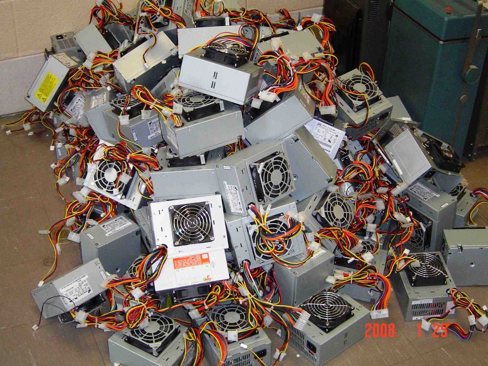
 I’ve noticed a few spirited discussions regarding modifying computer power supplies for use with Amateur Radio equipment. On the surface it seems as though they supply the perfect solution: Inexpensive, high current, regulated 12V DC supplies for a fraction of the cost of specialized amateur equipment. Is it really is as straight forward as lopping off a molex connector and replacing it with an Anderson Powerpole?
By design PC power supplies are designed to output a fairly well regulated 3.3V & 5V to the PC motherboard and 12V to the motherboard, fans and hard-drive motors. Modern units are typically rated anywhere from 75W to 1200W which should be a measurement of the output power available from all the 3.3, 5 and 12 volts. Since this isn’t a lab grade power supply you can expect marketing hyperbole has perhaps inflated the power output figures.
Back when my job was to build PCs I had an issue with a server not being able to start its complete complement of disk drives. When I opened the case I found a 300W desktop supply board had been used in place of the 800W board … sometimes you don’t even get what you pay for!
Before you convert your first PC power supply there are two issues that may, or may not, cause a problem depending on your unit.
The first is load regulation or the ability of the power supply to maintain its rated voltage under load. If the output voltage drops too far your rig will shutdown, distort or fail to provide its rated output power.
The second issue is due to the high frequency switching circuits used in switch mode supplies. Depending on the individual power supply there can be adequate to no filtering to prevent radio frequency interference being broadcast to your receiver. Toroids on the input and output lines can help to reduce interference.
 Because of construction differences between models and even between batch numbers for the same model you can never be certain how the power supply you purchase, or recycle, will perform. For the most part people’s experiences have been positive but I have heard of power supplies that were unusable because of RF interference or such poor load regulation that the 12V rail dropped to 11V under load.
Without a motherboard presenting a load and supplying the power-on signal there are a few changes that need to be made to the power supply. Modern power supplies will not enable the 12V output unless the power-on wire is grounded and a load should be placed on the 5V line to help with regulation. Additionally there is usually an adjustment that can be used to raise the voltage above 12V
The following links detail the steps required to convert a PC supply for use with amateur radio equipment. Whether this represents a good investment of your time will depend on your desire to do-it-yourself and the quality of the power supply you begin with. I’ve heard strong opinions either way but I’ll just say that, if luck favors you, you’ll save some money and learn a few new skills in this exercise.
Computer Power Supply Converted for Ham Use
CONVERTING COMPUTER POWER SUPPLIES (Advanced with theory)
Converting Computer Power Supplies to stabilized 13.8 V DC 20 A
Newsflash: Not Everyone Is Going to Be an Expert
You’ve probably run into this situation…some of the more experienced radio amateurs commenting about how so many of the newer hams are incompetent. “Yeah, they’ve dumbed down the FCC exam, so now anyone can get a license. Back when I got my license, I had to copy Morse Code in my head, design a triple-feedback-loop vacuum tube amplifier and recite the Gettysburg address backwards in front of an FCC examiner.”
A while back, I wrote about the time when a newbie on an email list asked a simple electronics question and got this reply: Not to pick on you, but is there any requirement these days to have a basic knowledge of electricity and/or radios to get a ham license?
Often this shows up as an elitist attitude of If you don’t pursue the hobby my way or at my level, then you are doing it wrong.
Since amateur radio consumes most, but not all, of my hobby time, it is easy to lose perspective on this. And, yes, I am sure I have complained about clueless newbies and LID operators from time to time.
It’s interesting to put the shoe on the other foot and think about activities that I pursue with much less time and intensity. In other words, think about activities where I am not that experienced and certainly not an expert.
For example, I enjoy fishing but I am really not that skilled at it. For me, fishing is just an excuse to sit next to a stream and enjoy the scenery. If I catch fish, that is a plus (but I always throw them back in anyway). When I encounter Real Fisherpersons, they are usually friendly and helpful, passing along a few tips on what they using for bait, etc. Sometimes I will encounter That Fly Fishing Guy that looks down his nose at any form of fishing that does not meet his high standard.
I also enjoy photography. I have a decent Canon DSLR camera with a few lenses and I manage to capture some reasonably good photos that way. (This probably has more to do with the quality of the camera than the photographer.) My interest is mostly to capture experiences and events in my life and create photos that I can use in my various writing activities. But I know a number of people that are infinitely more skilled than I am. They are generally very helpful and I usually manage to learn something from them. Come to think of it, I have not encountered very many condescending photographers — most of them have been very helpful. Maybe I have just been lucky.
Although it’s a cliche, Life is Too Short. There are so many things we can choose to do with our time and, really, so little time to do it. People must make choices about how deep they get into any activity, all while balancing family time and demands at work. It shouldn’t surprise us when some people choose to be part-time hams and don’t aspire to be the expert in all things radio.
And the final point is, if you think you have something to offer to the newbies, make sure you come across as helpful and make sure it looks like you are having fun. Being the Old School Grumpus will not attract people to your favorite activity. Having fun and inviting them in will!
73, Bob K0NR
Handiham World for 07 March 2012
Welcome to Handiham World.

On March 5, 2012 the latest version of the United States Amateur Radio Bands chart from ARRL became effective. If you will recall, last November the FCC made some changes to the 60 meter band, and this new chart brings us up to date. Of course that will mean that you will want the latest version on your computer or in your ham shack for reference. Prior to this week, only upper sideband operation was allowed on the channelized 60 meter band. Few of us had actually made the move to 60 meters and made contacts, partly because of the odd restrictions in frequencies and modes, but also because many antenna systems just didn’t tune on 60 meters. Even so, those who were adventuresome took the plunge and were delighted to find that propagation on 60 meters made it quite a useful alternative to 75 and 40 meters since it has characteristics of both of those popular bands. This morning I was surprised to be listening on 5.330.5 MHz and hear a station in the southeastern United States calling CQ using CW at around 30 words per minute. He called off and on for perhaps 15 minutes, obviously using a programmed keyer before he was finally answered by a station somewhere on the East Coast. I have to admit that 30 words per minute is too fast for me to copy comfortably, so I had to listen up to make sure I was hearing correctly. After all, only upper sideband operation was allowed on the 60 m band. When I was sure I was copying the call sign correctly, I decided to check the frequency chart on my wall just to confirm that only upper sideband operation was allowed. The chart confirmed this, but then I recalled the changes that the FCC had made and decided to check the ARRL website for a new frequency chart. Sure enough, a new version was available and had been released just two days ago!
The difference is pretty significant, because the effective radiated power, the modes of operation, and even one of the channelized frequencies have been changed. Let’s go over the “new” 60 meter band as shown in the ARRL Frequency Chart. Here is the new information for our blind members in an easy to listen format:
The 60 meter band is also known as the 5.3 MHz band. Only General, Advanced, and Extra Class licensees may use 60 meters. All of these license classes have full band privileges.
The five channels available on a secondary basis with a maximum effective radiated power of 100 W PEP relative to a half wave dipole are:
5.330.5 MHz
5.346.5 MHz
5.357.0 MHz
5.371.5 MHz
5.403.5 MHz
Some readers and listeners may find it odd that we have listed two decimal points in each frequency. I decided to do it that way because this preserves the concept of the “5.3 MHz band”. The ARRL chart lists kilohertz, so that the frequency would read 5330.5 kHz, for example. On my ICOM IC-7200 transceiver the readout follows our listing in megahertz and has two decimal points.
Only USB suppressed carrier voice, CW, RTTY, and data such as Packtor 3 transmissions are allowed on the 60 m band.
There is a bandwidth restriction on 60 m. Bandwidth is limited to 2.8 kHz centered on 5.332, 5.348, 5.358.5, 5373, and 5.405 MHz respectively. (For example, you will be on the right frequency if you use upper sideband and tune to 5.330.5 MHz, which is the carrier frequency.)
All things considered, the 60 m band has been improved by these changes. It is still quite unique in its channelized nature, but the addition of new modes of operation do increase its versatility and will make it more attractive to a wider variety of users. Although there is no restriction on which mode of operation may or should be used on which channel, I did hear the CW station on 5.330.5 MHz, perhaps because that is the traditional lowest frequency spot on the band where CW operators might decide to congregate. Perhaps at some time in the future there will be at least an informal band plan beyond the more or less agreed upon use of 5.403.5 MHz as a DX frequency. The increase in power from 50 W to 100 W makes the band more useful still, especially during summertime band conditions when more power is likely to be needed to be heard above thunderstorm static.
I hope you will consider giving the 60 m band a test drive if you have a General Class license or above and an antenna that can be tuned to 5.3 MHz. I think you will be surprised and delighted with the propagation characteristics on 60, and will likely add it to your regular list of useful frequency bands.
For Handiham World, I’m…
Patrick Tice, [email protected]
Handiham Manager
ARES Center Stage at 2012 MNVOAD Training Conference
 I’m off and running with the online ARRL course on Emergency Communications! Already I’m learning new things. Take VOAD’s, for instance — I’d never heard of them in my life, but now, thanks to this course, I’m signed up to attend the 2012 MNVOAD Training Conference.
What is a VOAD? VOAD stands for “Voluntary Organizations Active in Disaster.” The first VOAD (and still the main VOAD) was NVOAD (National VOAD), born in 1970:
Hurricane Camille led to the formation of NVOAD. After Hurricane Camille, it became clear that voluntary agencies were responding to the needs of disaster victims in a fragmented, uncoordinated manner. Representatives from several voluntary agencies began to meet on a regular basis to share their respective activities, concerns, and frustrations in disaster response. On July 15, 1970, representatives from seven voluntary agencies came together in Washington, D.C. to form NVOAD. (FEMA course IS-288, “The Role of Voluntary Agencies in Emergency Management,” 2-11)
Those first seven agencies were the American Red Cross, Christian Reformed World Relief Committee, Mennonite Disaster Service, National Catholic Disaster Relief Committee, Seventh Day Adventists, Society of St. Vincent De Paul and Southern Baptist Disaster Relief. Now there are nearly 50 agencies involved, including the ARRL:
The mission of NVOAD is to foster more effective service to people affected by disasters. NVOAD, itself, does not deliver disaster response and recovery services. NVOAD coordinates planning efforts by many voluntary organizations responding to disaster. Member organizations provide more effective service and less duplication by getting together before disasters strike. Once disasters occur, NVOAD or an affiliated state VOAD encourages members and other voluntary agencies to convene on site. This cooperative effort has proven to be the most effective way for a wide variety of volunteers and organizations to work together in a crisis. (4-9)
The state VOAD movement began five years after NVOAD was born:
Not long after the development of NVOAD, State and regional VOAD organizations were created to ensure an effective response to disasters at the State and local levels. The first State VOAD was formed in 1975. The VOAD movement initially grew without much order and without official sanction or direction from NVOAD. However, in 1988 NVOAD developed formal procedures for chartering State and local VOAD members. At this time, there are chartered State VOAD organizations in almost all the U.S. states and territories, and there are a growing number of local VOADs. (4-13)
The Minnesota VOAD has 37 member organizations, including the ARRL — and this year, RACES/ARES is taking center stage at the 2012 MNVOAD Training Conference on Saturday, March 24. The keynote speaker is Peter Angelos, KCØKRI:
9:00-10:00 Keystone Session – Pagami Creek Fire Response – Peter Angelos
The Lake County Emergency Management response to the Pagami Creek Fire (September 2011) and the role Lake County RACES/ARES played is a good example to illustrate effective and successful use of affiliated volunteer organizations in incident management. This presentation will outline a brief description of the incident, the specific support that RACES/ARES provided for logistical and situational communication, and most importantly–the organizational practices and principles that lead to success.
I’m looking forward to hearing what Mr. Angelos has to say about how RACES/ARES helped fight the Pagami Creek Fire.
But perhaps even more valuable for me will be the rest of the training day, which has nothing to do with Amateur Radio. After all, the whole point of VOAD is to learn how to work with one another efficiently and effectively when the time comes!


![]()
DIY Magnetic Loop Antenna – Part 3
Well, I finally have had time to sit down and put together part three of the DIY Magnetic Loop Antenna, sorry it has taken so long!
This post will cover building and coupling the loop to your transceiver. After reading through posts one and two you should have a good idea of the parts you’ll use and the physical dimensions of the main loop.
DIY Magnetic Loop Antenna – Part 1
DIY Magnetic Loop Antenna – Part 2
Most magnetic loops have the capacitor at the top of the main loop and the gamma match or matching loop at the bottom, this arrangement avoids running the feed-line through the center of the antenna.
You can assemble the main loop from continuous copper tube or from eight straight sections and 45 degree joiners. Make sure you have a blow torch or propane torch to solder the joints as you’ll need more heat than a soldering iron can supply. Whichever way you decide to build the main loop make sure that all joints are soldered or clamped as securely as possible, you want the lowest resistance possible to avoid your output power turning into heat. Other materials can be used for the main loop such as aluminium or low loss coax but copper pipe is easy to work, has low resistivity and available from just about every hardware store.
To construct the frame of the antenna you can use PVC pipe. It is a cheap and relatively sturdy building material and is available in a range of thicknesses, just about any hardware store will stock a wide selection of fittings. It insulates well and can be glued once you are sure your project is in its final form.
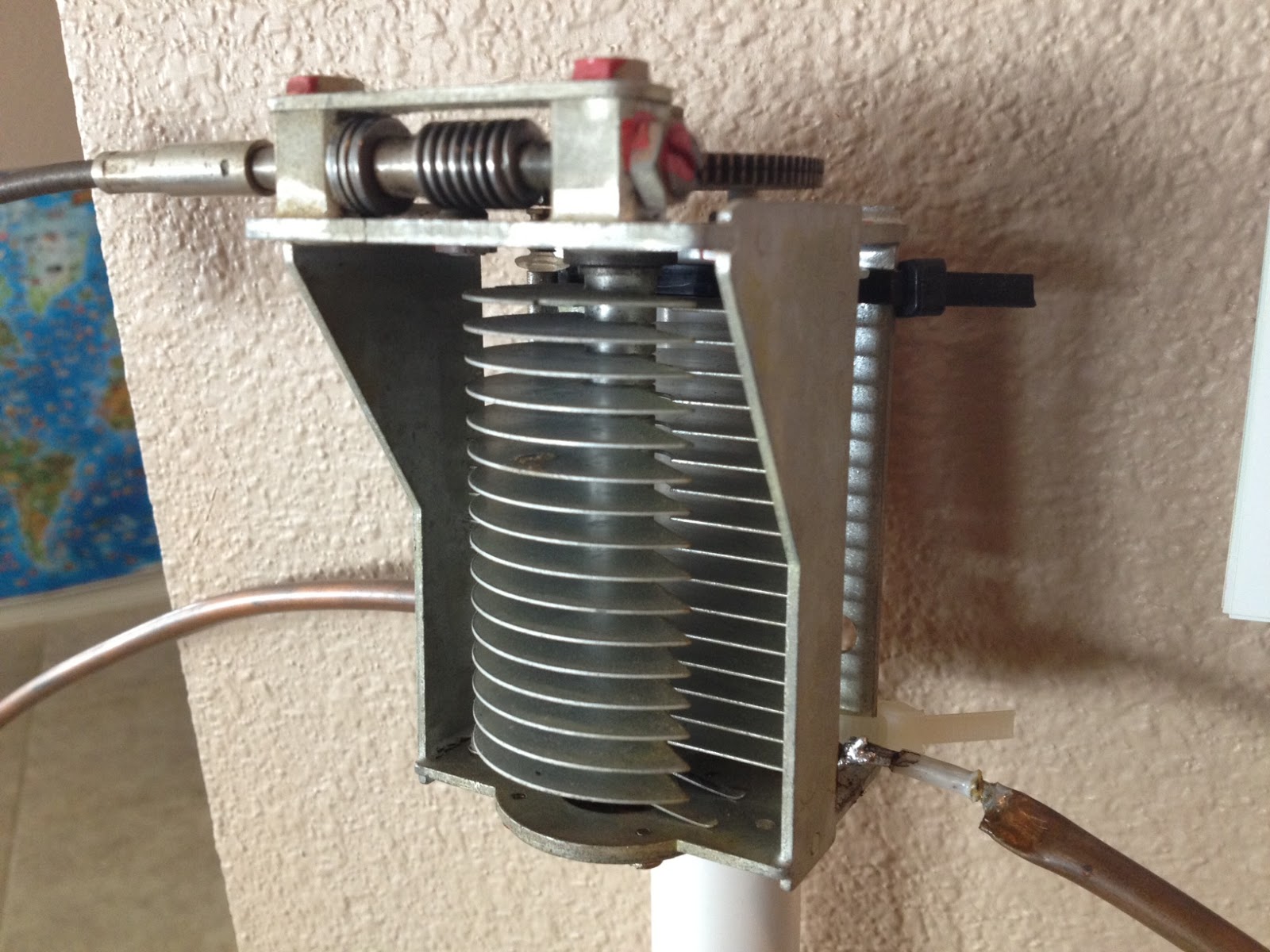
Once the main loop is constructed you’ll need to connect your capacitor to the two ends of the pipe at the top of the loop. Depending on the capacitor you may want to solder tags to the ends of the loop so they will be easier to attach. Copper pipe is a great conductor of heat and takes a lot to heat up and solder while it is not advisable to apply the same amount of heat to your capacitor.
It is also a good idea to attach the capacitor to a solid support so that the connections are not under strain.
The main loop and the capacitor forms the resonant circuit of the magnetic loop antenna.

To couple the main loop to your transceiver and match the expected 50 Ohms impedance you can use one of two methods. Probably the easiest is to use is a loop of insulated wire 1/5 the circumference of the main loop. The smaller loop is placed at the bottom of the main loop and can be shifted around to provide the best match. If you have an antenna analyzer you’ll be able to set it to the desired frequency, tune the variable capacitor for resonance and then move the small matching loop around till you have achieved close to 1:1 SWR. If you don’t have an antenna analyzer you can tune the capacitor for the greatest received noise and then on low power tweak the capacitor and move the coupling loop around for best SWR. Do NOT touch the loop while it is transmitting, use a wood or plastic rod to make adjustments as there are high voltages and intense RF fields near the loop.
An alternative to the coupling loop is the gamma match. The shield of the coax feed cable is connected to the base of the main loop while the inner conductor is connected to a point approximately 1/5 of the circumference around the loop. Its a good idea to use stiff wire (large gauge) for the gamma match as it can be critical of the position and orientation and once you have it in the right position you won’t want to move it again.
It would be preferable to have the ability to remotely tune the loop. A motor with a reduction gear could be used to move the variable capacitor but because the point of resonance is very narrow there should be a way of slowing the motor down. A simple control circuit using variable pulse width modulation could be used to slow the motor down while still retaining enough torque to move the capacitor. Whatever method is used to move the capacitor it should be well insulated from the other components of the antenna. Several thousand volts are generated on the MLA and care should be taken to ensure they don’t find their way onto control leads and back into the shack. Control leads should also be wrapped around toriod inductors as they leave the near field of the antenna to reduce the possibility of RF travelling along them.
With a SWR bridge and microcontroller you could build a fully automatic tuner that swept through the range of the tuning capacitor when the SWR rose above a defined limit indicating that the transmit frequency had changed.
With a little creativity and knowledge you could have an impressive MLA the equal of multi-thousand dollar military style units.
Hopefully this has given you some ideas for constructing your own loop antenna. Regardless of if you go top-of-the-line and buy a vacuum variable or build for economy and QRP you’ll have a compact, useful and unique antenna.
CQ CLASSICAL MUSICIANS DE NØIP
How many of you ham radio operators are also classical musicians? (I’m using “classical” loosely here, the way NPR does — not merely referring to the classical period per se, but broadly referring to all music of higher artistic expression.) I’ve always been intrigued by this kind of simultaneous development of artistic ability and scientific/technical ability. I’ve long heard that the two complement one another nicely, e.g. I’ve heard that musicians make better programmers.

Rehearsal of Exultate Festival Choir and Orchestra (Kristi Brackett, Photographer)
Right now I’m working hard with the Exultate Festival Choir and Orchestra to get ready for an upcoming performance of The Messiah by George Frideric Handel. Ham Radio has taken a back seat in my life during this seven-week project (as well it should, if we have our priorities straight). Yesterday’s rehearsal in the Twin Cities was exhilarating, and once again proved that the 2 1/2 hour drive to get there is definitely worth it. Dr. Tom Rossin is an outstanding conductor, and the choir is so good I have to pinch myself sometimes to see if my place there in the bass section isn’t just a dream. (If any of you happen to be in the Twin Cities on the weekend of March 9-11 and would like to hear The Messiah in its entirety, send me an email and I’ll email you a coupon that will get you two tickets for the price of one.)
Music was part of my life as a boy before I became a ham, but it didn’t blossom until 13 years ago at the age of 31. That was when my brother Tom (NØBSY) got me involved in a cappella shape-note singing from The Sacred Harp. This taught me how to sing parts; without it I could never have gotten into choral singing the way I have. My first choral work was with Exultate, singing Bach’s Mass in B-Minor, followed by Brahms’ German Requiem (in Rutter’s English translation). Since then I’ve been involved in a small choir here in the church, too. All of this has been a huge surprise to me. Up until I was 31 years old I was afraid to sing in front of other people, and I couldn’t sing parts if my life depended on it! So if any of you think you can’t sing, think twice — you might be surprised at what has been lying dormant in those vocal chords of yours, just waiting for the proper nudge to burst forth into beautiful song.
I see Tyler Pattison, N7TFP, is not only an accomplished ham radio operator but an accomplished musician. Along with his excellent tutorials for ham radio operators, Tyler has also posted a video of his performance of Charles-Marie Widor’s Toccata in F from Symphony No. 5. In this video you can see the organ from Tyler’s perspective, not only as a musician but as an electrical engineer. He is bringing both sides of his brain to bear upon the magnificent task of rebuilding and upgrading this organ — and then making beautiful music on it.

How many others like Tyler and myself are out there? If you are a musician and an amateur radio operator, what do you think? Has one influenced the other in your life? How?


![]()
Handiham World for 29 February 2012
Welcome to Handiham World.
Ice! Are you ready?

Photo: Ice and snow cling to the dipole at the WA0TDA station in Minnesota. The 450 Ohm feedline and the antenna wire are carrying a coating of heavy ice, as are the nearby tree branches.

Photo: Iced birch tree branches pull the antenna wire down.
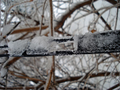
Photo: Heavy ice coats the 450 Ohm ladder line in this close-up.
Here it comes: The annual Spring severe weather season is here in North America. Tornadic winds hit in the southern Midwest states of Missouri and Kansas last night, while the same huge weather system brought Minnesota freezing rain and snow. The transition from winter to summer often means that we will be visited by bad weather that can take down antennas and put stations off the air at the very time their communications capability may be needed. This storm was well-forecast because it was being watched even as it approached the west coast from the Pacific. Computer modeling lends a new degree of confidence in such forecasts, so it is perhaps a bit easier than ever to be ready.
The problem for any given amateur radio operator is that forecasts cannot predict exact weather circumstances in a small geographic area. In this particular storm, heavy snow fell north and west of my location but we only got about 3 inches worth. Our snow was preceded by rain – freezing rain – which coalesced around antenna wires and tree branches. When the snow came, it added to the mass already collecting on the branches and wires. This was a prescription for power outages because tree branches would inevitably begin to break under the weight of the ice and fall across power lines. The power lines themselves, if in the clear, seldom collect enough ice to fall on their own. Sure enough, this morning almost 15,000 customers were without power here in the Twin Cities. Since the storm was more severe in the northwest part of the urban area, that was the place with the most power outages. Even so, in my town there were over 400 customers without power. Our power never failed or even flickered, probably partly because of just plain luck and good switching at the power company to keep failed power lines from bringing down the entire system. One thing I looked for specifically when purchasing my property was underground power lines. I have lived in too many neighborhoods where tree branches fell across lines and cut the power in almost every severe storm.
So what can you do to keep your own antenna systems from failing under the weight of snow and ice?
Wire antennas should be installed so that they have some “give” to them. That means that if the wire should be stressed by the extra weight of ice, the antenna will be able to bend with the weight enough to avoid outright failure. There are various methods of making a wire antenna a bit more flexible. The obvious one is to make sure that when the antenna is installed that the wire is not pulled up tight. Sometimes ingenious methods can be designed to allow an antenna anchored in a tree to move freely as the tree moves in the wind. Usually unless the tree is exceptionally flexible it will be enough to simply allow enough slack in the antenna wire to make for reasonable movement.
Rigid metal antennas are another story. Most amateur radio beam antennas are made of aluminum tubing. Some types of aluminum tubing are “aircraft grade” and may flex more than standard tubing before breaking. No matter what kind of aluminum tubing is used, it is not immune to severe damage from ice loading. If the weight of the ice itself bending the aluminum doesn’t break it directly, wind that comes up after the ice is coated onto the elements may very well finish the job and bring the entire structure down in pieces. I am not sure that there is any practical way to prevent this kind of damage in a beam antenna system, but perhaps someone with experience can weigh in on the matter and let us know. Few amateur radio operators have tilt over towers that can perhaps be used to bring the whole antenna down close to the ground with the elements 90° to the surface of the earth so that water will run off of them. But what happens to the horizontal portion of the tower that will then be collecting ice? It’s hard to figure out how to prevent ice damage on a beam antenna system, so keep your insurance paid up.
An antenna that is coated with ice and snow will not necessarily tune correctly. When I tried using the LDG auto tuner this morning to tune my 200 foot wire antenna on a frequency that had been previously “memorized” by the tuner, it behaved exactly as if it were visiting that 75 m frequency for the very first time. The tuner cranked away for a while before finally settling on what had to be a very different combination of capacitance and inductance to allow for a reasonable standing wave ratio. Once the ice melts off the wire, the auto tuner will have to search again for a new combination as things return to normal. One thing to consider is that not all automatic tuners will be able to match an antenna that is heavily loaded with ice and snow. The operator must be aware of this and be careful not to operate with a high standing wave ratio.
The antenna wire itself is not the only thing affected by ice and snow. If you are using open wire feed line as I am, you can expect ice loading on the feed line to contribute to changes in how the antenna behaves on the air. If you use coaxial cable, your only real concern is weight of the ice on the cable itself. Any place feed line comes into the house it should have a “drip loop” so that water can drip off the bottom of the loop of feed line as the ice melts. This prevents the water from following the cable through the wall of the house and into the ham shack.
Your antenna system will be more robust if you use good quality materials to construct it in the first place. Good antenna wire may be more expensive initially, but it will be more likely to stay up under ice loading than some bargain wire. As the old saying goes, “a chain is only as strong as its weakest link”. In terms of a wire antenna system, this means that a cheap insulator could easily be a failure point no matter what kind of expensive wire and feed line you use. Needless to say, you should always take the time to secure wires properly to center and end insulators so that it will not work loose under pressure as ice pulls on the wire.
Following a weather event such as high wind or icing, you should plan to inspect your antenna systems for any possible damage or tree limbs that might’ve fallen against the antenna wire. Any kind of antenna system should always be located well away from power lines so that a failure in either the power line or the antenna will not make one of them come in contact with the other.
Tomorrow it will be March, and that is the month that I usually think of as being the start of this severe weather transition season. Maybe it’s time to take a look at that go-kit and make sure that you are ready.
For Handiham World, I’m…
Patrick Tice, [email protected]
Handiham Manager


