Author Archive
 Your LF Station’s Best Friend – The Scopematch PT. I
 If you're planning to get on Canada's newest ham band (630m), or are in the U.S. A. and building for when that day arrives, then you'll probably be interested in today's chatter.
Several years ago, when I first set up my 2200m (136KHz) station under Industry Canada's Amateur Experimental Licensing Program, I utilized a fairly simple method shown in the LF Handbook, of attempting to tune and load my antenna. I had built a small top-loaded wire vertical consisting of a two-wire 50' flattop at the top end of a 30' vertical wire. A large loading coil of about 3 mH at the base of the antenna took care of getting the system close to resonance. As shown below, a variometer was used to fine-tune the system to resonance while the antenna impedance was matched to 50 ohms by tapping up from the base of the loading coil.
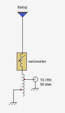
A 2A RF ammeter was used to monitor antenna current, with the plan being to tune and tap for maximum antenna current. It was the first time I had done any LF antenna work like this so it was a true 'learn as you go' project. It sounded fairly simple in theory but actual implementation was more challenging than I thought. What I also should have had was an LF SWR meter in the 50 ohm line as tuning and tapping for maximum antenna current did not guarantee that my system was indeed resonant or impedance matched. As you can imagine, there was much interaction between the two adjustments and I often found myself chasing my tail.
There were some tuning combinations that would peg the RF ammeter, indicating more current than my system was even capable of producing into a 50 ohm load. No doubt my settings were sufficiently 'off track' to create some diabolical impedance / off-resonance combination. I eventually settled on something that looked close but I was never really sure. Several weeks later I built the 'Scopematch' (designed by Jim Moritz -'MØBMU) and have not had a problem tuning and matching ever since.
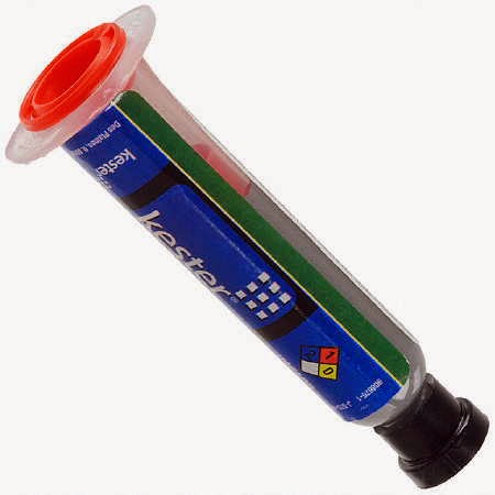
Of all the devices in my LF toolbox, the most valuable by far is my Scopematch. Basically, it is a coupling device that allows you to monitor the tuning parameters of your LF antenna system. In real time, you are able to see both the impedance condition and the resonance tuning condition by observing the antenna current and voltage waveforms on a dual-trace oscilloscope. It is immediately apparent if your system is impedance matched (or not) and how close to resonance the system is. It will even tell you if your antenna is capacitive and requires more inductance to lower the frequency or if it is inductive and requires less loading inductance to bring it up in frequency.
Besides the dual-trace scope, the Scopematch requires only three parts and is fairly non-frequency critical. I am able to use it on both 2200m and 600m without any changes. More details to follow.
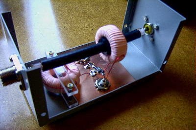 |
| My homebrew Scopematch |
The ‘Snowman’ Pays A Summer Visit – VYØSNO That Is!

If it seems like I'm talking a lot these days about 6m, that's probably because it's my main operating interest during the summer sporadic-e (Es) season, which is already starting to wind down. In a couple of weeks it will all be over for another year, allowing me to focus on other radio activities.
But, should you plan to venture forth into the magicband's world, proceed with every caution....there are powerful forces at work there!
Before this week I had never heard the VYØSNO 25 watt 6m beacon. The 'snowman' is 2,250 miles away and located in the Canadian Arctic town of Iqaluit, Nunavut, the coldest city in Canada....talk about the ideal call!
 | |
| Courtesy: Google Maps |
The beacon has shown up briefly here, twice this week, with both events in the evening and lasting for only 10-15 minutes. Although there are no longer any active 6m hams in VYØ, it is still thrilling to hear these summertime signals from the Arctic....and in this case, directly in line with Europe and better than halfway there!
At one time the beacon had a different call, VE8BY, which I usually heard once or twice each summer. Since the change to a new transmitter and to a new call, for some reason it remained unheard for several seasons...until this week.
The old VE8BY beacon was unique in that its transmitter was frequency-shift-keyed (FSK mode). The dots and dashes were a few hertz higher than the actual carrier frequency. Hearing the melodious keying in combination with the typical Arctic flutter always made the arrival of VE8BY something very special as can be heard in this capture by Kevin, VE3EN....
Unfortunately, Larry (VYØHL), the owner and operator of VYØSNO/b, has moved from Iqaluit and will no longer be able to maintain or repair the beacon should it have a future break down. Hopefully it will continue to run reliably for many more years as E-season would just never be the same without a summer visit from the 'snowman'.
Russian TV…6m’s Little Helpers
 |
| London's Crystal Palace TV Tower |
Parked conveniently close to 6m, the 49MHz multi-kilowatt transmitters combined with large high antennas to pump lots of ERP over the pole. Surprisingly, there are yet a few holdouts of the analog era that are still available as propagation indicators, with most of them being located in western Russia and the middle-east. Far eastern Russia also has a number of the analog relics in Siberia and in the Vladivostok / Kamchatka regions, all of which which make great indicators for possible openings to Japan, China and Taiwan. During good openings to Japan, it is not unusual to hear several different signals all on the same frequency but with different fade rates and tone / sync characteristics. During the past few strong solar cycle peak years, spurs from these Russian transmitters could often be heard at S9 levels well into the 6m band!

Although there are numerous others, from my own experience the best frequencies to monitor for both European and Asian transmitters have been:
- 49.750
- 49.757.8
- 49.760.4
During Sunday's VE6-Europe 6m opening, several of these signals were heard even though no Europeans were worked from the west coast. Video carriers on 49.750, 49.760 and 49.757 were heard for over an hour, peaking around 1800Z.
The two unique characteristics of these video markers has always been their rapid fade rate and their somewhat raspy video-sync pulses....both can be heard in this short video that I captured during Sunday morning's activity. The stronger 49.757 signal can be heard as well as the weaker 49.750 carrier, while the 49.760 signal has taken a deep fade. I suspect that the louder signal is coming from the Novosokolniki transmitter north of Moscow while the weaker ones may be further to the south. These locations are simply 'best guesses'.
This recording of eastern Russian video carriers, made by JM1SZY, provides a good idea of how these signals sound when they're much stronger. Note also, the number of different frequencies that the different transmitters are using.
It is very difficult to know exactly where the actual transmissions are coming from as there are dozens of transmitters assigned to the same frequency. Most signals do vary from their assigned frequency by measurable amounts and some avid DXers have tried to identify individual sites by accurate frequency measurements.
Since the digital switchover, interest in keeping track of the remaining signal data seems to be falling off and most frequency and location lists are now several years out of date. The most up-to-date lists can be found here on the GØCHE Website and on JB's DX Info site in Germany.
If you're anywhere east of the Great Lakes then you'll hear the European videos a lot more often than they are heard out west but it still astounds me that several times each summer, I am able to hear TV signals from Europe over the North Pole!
6m Polar Fun / VE6 To Europe
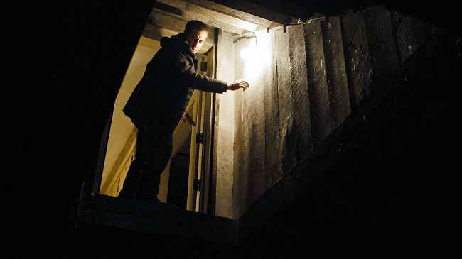
When you find hams heading for dark basement shacks in the middle of a glorious summer day, chances are they're 6m nuts like me. Sunday morning was a good example of why the magicband can become so very addictive.
For west coast fanatics, the 6m Holy Grail is working Europe. Such summertime opportunities via multi-hop sporadic-E (Es) are very rare and usually very short-lived, so the biggest challenge is just being in front of the radio for those few moments when things 'go polar'.
From here in VE7 land, our best propagation indicator for possible polar openings is the 12 watt VA5MG beacon on 50.034MHz, located in central Saskatchewan. It is rarely heard....but if and when, it often heralds the possibility for some memorable moments for some lucky left-coasters.
Such was the case this past Sunday morning...almost. My normal workbench 'background music', the quiet white-noise hiss of a programmed scan for northern beacons (50.015-50.050), suddenly filled with signals shortly before 0930 local time. The VE4SPT beacon in NE Manitoba and the VA5MG beacon were soon joined by VE8WD/b in Yellowknife, Northern Territories and VY1DX/b in Whitehorse, Yukon. Game on! ..... the north was alive with Es, signalling the all-important first-hop stepping stone to Europe was in place.
After alerting a few dinner-bound Europeans via the ON4KST 6m chat page, I began a prolonged period of over-the-pole CQ's on 50.086. About 30 minutes later, there were a few other west coasters doing the same, along with VE6TA near Edmonton, who was hearing the 15 watt VYØYHK beacon on King William Island in the Canadian Arctic.
 |
| VY0YHK Courtesy: Google Maps |
I continued to CQ for some time, but the most I could muster were three separate callers at various times, all too weak to identify. I later learnt that I was heard by SM2A, who called with 50 watts, as well as DL6HL. It seemed that VE7 was just on the far edge of whatever might be happening. For VE6TA however, the magic was much more powerful.
Having only worked two Europeans in several years on the band, Grant bagged six Europeans over the next 30 minutes, hearing ''tnx first VE6" from a few very alert Europeans..... PA5JS, ON7GB, PA7MM, LX1JX, DL1QW, DH6JL and SM2A. Randy, VA6EME, further north in Cold Lake, Alberta heard and worked one European, ON7GB, as did Joel, VE6WQ in Edmonton. As is so often the case, on-the-ground signal footprints are usually very small and stations just a few miles apart can have a completely different experience.
The N3TUQ 6m DX Map starkly illustrates this exciting event, showing Grant in the right spot at the right time, for a very rare mid-summer event. In his own words, "My best day ever on 6m".......

...and this is why grown men will sit in dark basements on glorious summer mornings.
The Noise Whisperer

This past Friday, I had a very pleasant visit from Roy Charlesworth from B.C. Hydro. Roy is the Hydro's noise mitigation man for naughty power lines and made his way to Mayne Island on the morning ferry from the mainland.
For the past several years, I have been plagued with severe power line noise to my northwest, virtually killing my opportunity to take part in most 6m openings to Asia. The one or two small rain showers that we might get here in the Gulf Islands during the sporadic-E season, will often wash away enough of the power line crud to quieten things down for a few hours but as soon as the sun is back and the day heats-up, the noise always returns. For the same reason, the lines don't seem to get noisy until around 10 a.m., giving me some early-morning opportunity to listen to a dead-quiet band.
Earlier this spring, I contacted Roy and was added to his list of places to visit. He assured me that he would be over to check out my situation sometime during the summer. Roy is now officially 'retired' from Hydro and was doing similar noise mitigation work at that time. Once retired, Hydro found that his unique skills were still very much in demand and have rehired him on a 'work when you want' contract basis, allowing Hydro to still chip away at the list of complaints.
I recall, not too may years ago, when any complaints to B.C. Hydro about power line noise where just ignored and the only way they would act was if ordered to do so by Industry Canada. With the confusing bureaucratic channels involved, most amateurs just gave up and lived with the noise. Fast track to modern times, where all responsibility for noise mitigation has been placed in Hydro's hands and they are bound by IC mandate to deal with customer noise complaints.
It was apparent when first meeting Roy that he was very familiar with amateur radio 'noise problems' and very knowledgeable about their causes. After demonstrating the noise being heard on 6m on my own receiver, he then deployed a rather unique piece of test gear, a Radar Engineers Model 240 RFI Locator receiver. The 240 tunes from 1.8-1000MHz and is capable of displaying and saving the spectral display of the offending noise signal.
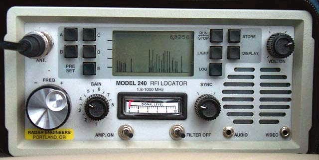
 Being able to see the signature and compare it to the actual suspected source goes a long way in helping to find and cure the problem. Before departing to search the local area, Roy's final check was to check my own house for any possible noise. A quick sweep of the electrical service panel using yet another receiver indicated all was well.
Roy also mentioned that he prefers working with hams since, compared with non-ham noise complainants, they seem very knowledgeable about noise in general and often have narrowed down the source for him...even providing the number of the offending power pole. I had also provided Roy with the numbers of two different poles. I was pretty sure about my number-one candidate pole but not so sure about number-two. Using the sharper pattern of my 9 element 2m Yagi, I was able to get a very good bearing on the noise source.
After being gone for most of the afternoon, Roy returned to explain what he had found. To my delight, he had found three noisy poles within my local neighbourhood, but to my surprise, none were the poles I had suspected! All three however, were on the same bearing as my prime candidate pole, but much further away than I had thought. He also confirmed what I had told him earlier, that all other directions were very quiet. He explained that he would file his findings with Hydro who would create a work order for eventual physical inspection and (hopefully) resolution of the problem. He would also contact me again once that had been done, to see if the noisy poles had been fixed.
I think we are most fortunate, here in B.C., to have a dedicated one-man power line noise mitigation man, in the person of Roy Charlesworth. He is clearly passionate about his task and understands just how devastating power line noise can be for radio amateurs. Unlike many regions in the U.S. where utility companies can stonewall amateurs for years and years, we presently have a very efficient recourse when power lines behave badly.
I sure hope Roy doesn't retire for 'real' anytime soon as I'm not sure he would be easily replaced!
To learn more about power line noise see:
More SMT Talk
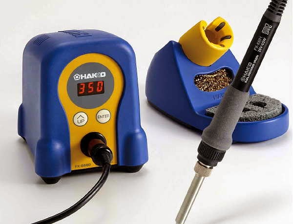 |
| Hakko FX-888D Soldering Station |
Jack was a NASA level B instructor for 26 years with Bristol Aerospace in Winnipeg, Manitoba. During that time he was instructing on an 'as required basis' but mainly working as an instructor and designer for the SCISAT-1 satellite. Worked involved all electrical systems, harnessing, manufacturing, designing of PC boards and all NASA hand-soldering and SMT soldering processes. That also included writing all the documentation for all the NASA processes used for the manufacturing and testing of the satellite electrical systems.
Although my first and only SMT experience several years ago resulted in the successful completion of a simple 40m transceiver, I found the process tedious and less than enjoyable. Jack suggested that my laborious technique was not the way to do it and was probably to blame for my negativity towards future SMT work. He gave me a wealth of encouraging suggestions for a more 'enjoyable' outcome:
Yes I agree our old eyes are not the same, but a good 6" magnifier ~2.25X lens with light (preferably incandescent IMHO), this is what I use plus a loop if needed for closer-up inspection. An alternate is a binocular magnifier with ~ 2.25X or better, they are widely used by inspectors, jewellers or home hobbyists.
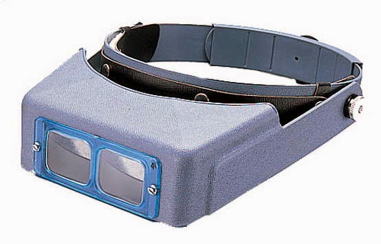 This is what I think I'll invest in next. Without these you haven't a hope or chance of doing the job as well, it is next to impossible. Sorry, not going to talk you out of building with SMT parts, We've gone from tubes to transistors and now to SMT, time to make the change :-)
 BTW, not sure what that instrument is that you have on the blog, looks something like a tool that may be used to hold down the chip while soldering. You don't need it.
Helpful hints if you so decide to go with SMT:
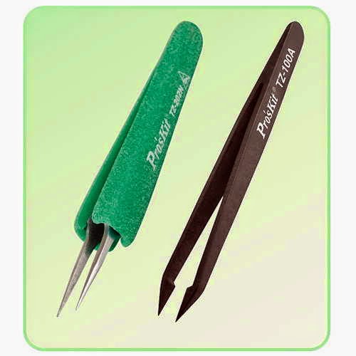
First purchase a good sharp pointed long ESD type plastic or metal tweezers.
Tack solder one side only, then go to the other side of the chip and solder it correctly, THEN go back to the 1st side and re-solder that side correctly, keep your dwell time to <3-4 seconds. Start with using a tooth pick and apply a small drop of solder paste on each side of the chips pads. If soldering a large 14-16 pin chip, tack solder one corner then the opposite corner first being careful to have the correct alignment/position. Now apply solder paste down the length of each side, don't worry if you apply paste between the pads as the heat will draw it away once you apply the tip. Slowly draw the long soldering iron tip down each pad starting from any corner, allow a few seconds to cool, then repeat for the opposite side. Fine solder will also work but it's slow and far more time consuming.
Use liquid paste SN63/PB37 eutectic solder {no plastic state} for best application, use sparingly as it's too easy to get some under the chip which can easily cause a short cct.
Hope that helps you and convinces you to give it a try.
 Personally, I prefer just 63/37 liquid paste in a syringe, far less cleaning up with IPA. Besides, using IPA means cleaning it 100% with a stiff bristle brush. Once the flux is exposed to IPA or rubbing alcohol, there is a chemical action that slowly takes place and it is quite corrosive if the area is not thoroughly washed. Besides, you can't afford to expose certain parts like pots that are not hermetically sealed, once the flux gets inside the pot is contaminated and becomes useless. It's OK to not clean your board, as long as you don't attempt to use any alcohol in a half-ass method. We used total immersion baths and not just one but three separate ones. Even then...I had to slowly pour pure distilled water over the board, capture it in a clean beaker then take it over to our chemical lab where they tested it for any flux residue. Those were required mainly for building all the satellite boards though. Most commercial manufacturers don't bother to clean their boards, a) one less manufacturing step, b) added cost and less chance of contamination. There are some no-clean solder pastes out there now, something to look into, see Digikey for examples. Don't worry about expiry date later down the road, mine expired in 2009! These paste manufacturers mainly deal with big companies that have a tight criteria to meet in order to comply with a wide range of standards imposed on them. Mine still works beautifully, I keep rotating it so the flux inside doesn't settle to just one side. Keeping it in a fridge can even extend the life, but don't worry about that, besides the xyl may not like the idea.
Yes, there have been many attempts back in the mid 70-80s to come up with a simple solution for a simple problem of having a third hand to hold the part in place while you hold the soldering iron with the other hand. NASA, ESA (European Space Agency) and IPC have never used anything like that since the very beginning. Although most hams probably wouldn't want to go to the trouble of learning NASA standards as it's a bit overkill, but it's far better than what some are portraying on the web as the right way to do it.
I'm not sure where that antiquated technique of using a large tool to hold down chips ever came from, but I'm guessing from hobbyists who meant well as they were not trained to know any other way. What hobbyists use for small work production are vacuum tools or what is referred to as "pick and place" machines or even simple ESD approved tweezers just to bring the part to the board. With solder paste already in place, the part is allowed to be placed onto its pads on top of the paste. The part is held with tweezers whilst the iron tip tacks one side for a couple of seconds then the tweezers can be removed, then the other side is heated. There is absolutely no need for a third hand. I see a lot of guys use regular small solder to do the soldering of SMT parts. Yes it can be used but it's awkward if you don't know what you are doing. Liquid rosin flux can also be used, a small bottle with a fine needle type end can be used to apply the rosin, followed by a small drop of solder on the end of the iron.
As I was saying before, if the part is an IC, then a couple of corners can be tacked soldered in place after careful alignment, then paste is run down both sides even between the pads. You don't see this process done too often as it's mainly for small manufacturing or where repair work is required. Now reflow ovens are used, even toaster ovens work quite well by hams. You just have to know the right temperature, paste and have the right dwell time in the oven. Yes tombstoning can occur on the odd chip, that is caused by the lack of uneven temperature control inside these small ovens. One side heats up faster than the other, so the part suddenly rises up on its end and stays there even after removal from the toaster oven. There is a wealth of good information out there on the web.
There are tons of YouTube videos out there that actually show the wrong process of soldering these small parts, but you can't blame them, they were not trained to know any better, but it gets them by as far as they are concerned. I've written many soldering processes on the correct methods on soldering SMT and regular through-hole parts over the years. I still have copies of all these documents which I could send you but they are huge documents.
There is a wealth of good information out there on the web like this one HERE ....does this look easy or what. Forget about trying to solder one pin at a time, that's old school method. Some videos are really crappy so you have to be careful what you select.
Sorry for being so long winded but I hate to see anyone frustrated not knowing how to do it or whether to go that route. Believe me, SMT soldering can be a hell of a lot of fun and one can get a lot of satisfaction and pride when you learn the right way, it's not as hard as it looks.
Many thanks Jack...your encouraging response has definitely given me new hope to tackle some future SMT work!!
Many thanks Jack...your encouraging response has definitely given me new hope to tackle some future SMT work!!
Wellbrook Loop Plans
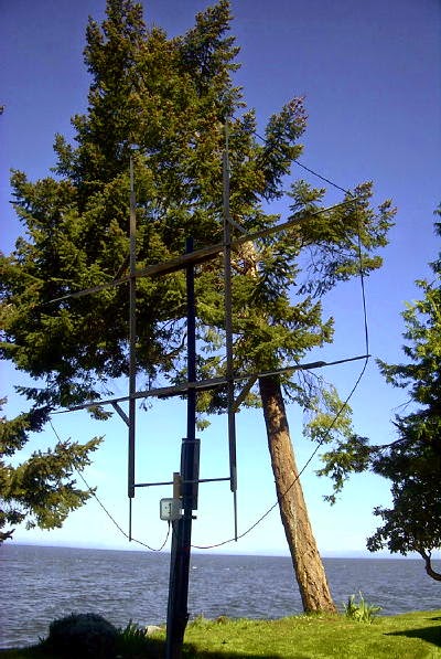 |
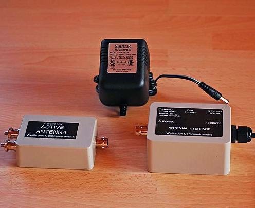
| My present 9.5' active loop |
During last winter's DX season I built and played with a number of different preamps for use with my (almost) 10' diameter shielded loop. I had been hoping to get the Burhans Preamp to play-nice above 500KHz so that I might use it for DXing the broadcast band with my new Perseus SDR radio. By bypassing the preamp's LPF, the level of BCB signal delivered by the 10' loop was just too much for the preamp's JFET front end to handle with the consequence being various strong intermod products showing up at several places inside the band. Several different toroidal input transformers produced varied results but none were satisfactory. Although I didn't try it, a smaller aperture loop might do just fine with the LPF removed and even better if there were no blowtorch BCB signals in the vicinity. My particular location, on the east coast of Mayne Island, looks directly across Georgia Strait to several 50KW BCB transmitter sites near the points of nearest landfall. Luckily, this direction is usually in the loop's null when pointing in my favorite target direction of SE/NW for the central U.S. Even so, it would be nice to not have to worry about loop orientation in order to guarantee intermod-free performance.
I did have much better success on the BCB using a version of the PA0RDT active antenna preamp, modified with transformer input to match the shielded loop's low impedance to the JFET amplifier input.
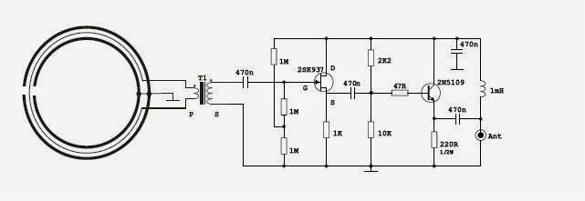 |
| Courtesy: Aldo Moroni |
Gain of the system was adjusted by swamping the transformer's output with various levels of 'R' until there were no signs of intermod products with the loop pointing away from the Vancouver blowtorch signals. The end result was a preamp that had good performance throughout the BCB, even with the big loop, as this recording of French language station, CJBC (860KHz) in Toronto(identifying as 'Radio Canada') demonstrates.
....but unless the loop was oriented in my favored SE/NW direction for most North American targets of interest, there were still a few frequencies that produced some very low-level intermod products. Again, had the loop been just slightly smaller, I think this preamp would do a great job as a wideband loop amplifier for the BCB and above. Although still usable down at 540KHz, performance dropped off rapidly as I went lower in frequency and was not considered usable for the LF NDB band. Perhaps more inductance in the input transformer as well as higher value coupling capacitors would improve LF performance. There is still room for further development of this circuit for LF use with a medium-sized shielded loop.
I recently ordered and received a Wellbrook ALA-100LN loop preamp, which I am anxious to install for the upcoming DX season. With its front-end of 8 JFETS in push-pull parallel, the Wellbrook boasts extremely good strong-signal handling capability within the BCB and below.
 |
| Please visit: http://www.wellbrook.uk.com/ |
My present plans call for a new and lighter loop frame, this time using PVC tubing in some sort of H-frame. I will aim to make the loop as large as possible while keeping within the Wellbrook's circumference limit of about 21m. Mid-summer doodling has produced one possible front-runner but no final decisions have been made.
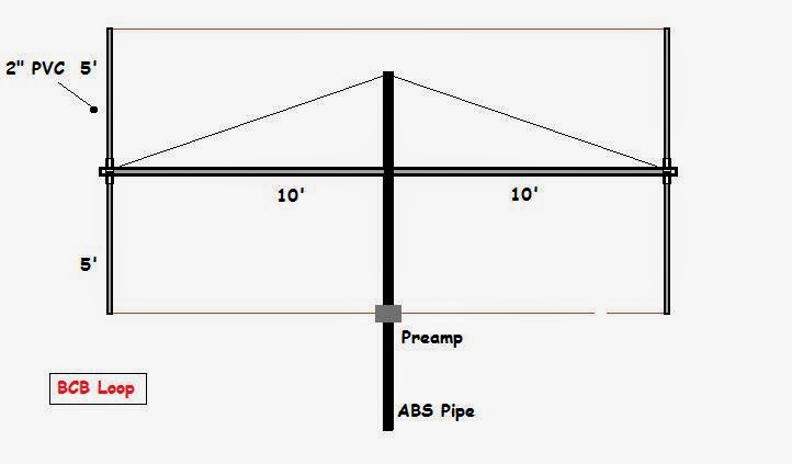 |
| 10' x 20' LF / BCB Loop |
I always savour the design and 'what-if' phase of any new project and the new loop is no exception. Any other ideas for possible frame configurations would be most appreciated.


