Author Archive
 New MOPA Completed
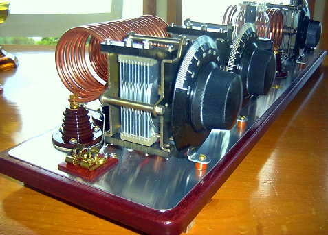
Well ... my new 1930's style MOPA transmitter is finally finished after several months of construction. I have also put together a page on my website describing the project.
For many years, December's high winds here on the coast, have always arrived coincidentally with the start of the annual 1929 QSO Party, making my signal dance around even more than usual! With the new MOPA, I'll no longer have to worry about high winds upsetting signal stabilty ... although many of us do enjoy hearing these musical sounds of '29!
By the way, there's still plenty of time for you also, to put something together for this annual fun event. You can see a whole page-full of inspiring '29 homebrew magic here (scroll to the bottom half) ... and there is plenty of help available for your project in the AWA Yahoo Builders Group ... we are always looking for more new activity, particularly here out west.
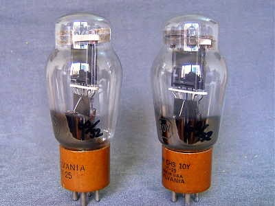 |
| courtesy: natubes.com/ |
I'm looking forward to working many of you in the next '29 QSO Party ... in the meantime, I'm thinking hard about what my next project might be!
A Versatile 630m Antenna

Mark, VA7MM, had come up with a nicely-designed antenna that will serve as his main 630m radiator. Not only that but it can be used on 10m, 15m and 30m and 160m as well!
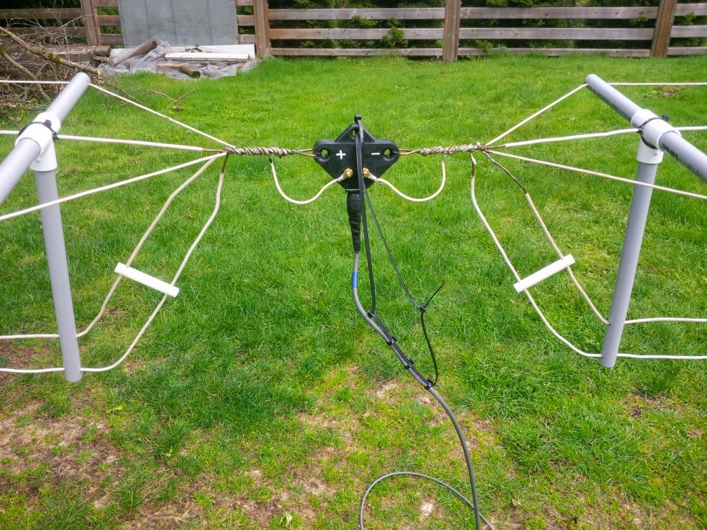
The antenna consists of a mini-flat top dipole, with three resonant dipole legs all terminating at a common feedpoint.

This can be used directly on any of the three high bands. Shorting the end of the coaxial cable, dropping vertically down from the feeedpoint, the dipole feedline becomes the vertical element of a top-loaded 630m 'T' antenna, 100' in the air.
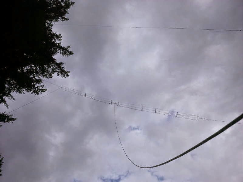
With suitable loading coils and appropriate switching, the 'T' will also be used on 160m, making the versatile antenna work on five different bands ... a nice demonstration of basic antenna principles put into real practice!
RTL SDR Filters
 |
| SDR Sharp GUI |
DXer John Bellini in Colorado, and maker of those informative Low Noise Vertical videos, has been at it again.
This time it's a good demonstration of a pair of filters that he built to mitigate the front end overload experienced on his SDR receiver.
John is one of many radio hobbyists that have been playing with the very inexpensive RTL 2832 SDR dongle receiver. Being very close to several high-powered broadcast stations has been a bit problematic for him when using the low cost SDR but his new video shows exactly what was needed at his location to solve the problem:
It looks like John is using the SDR Sharp GUI (graphical interface) to operate the dongle SDR receiver. Those wishing to learn more about this might find this 'getting started' page of interest.
Good stuff John.
Crystals Go To War
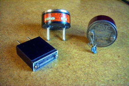
Thanks to a recent posting in the Yahoo ParasetBuilders Group, I have a new-found respect for my small collection of prewar crystals! If you've ever wondered how a rough chunk of quartz gets transformed into an accurate frequency-generating device, this 'cinema-style' documentary shows exactly how it was done ... truly an amazingly complex, yet delicate, labor-intensive process.
After viewing the documentary, I can't help but wonder what later health effects some of these workers may have undergone after seeing them handling some nasty-looking chemicals and working directly beside desktop X-ray machines. If you've used old WW2 crystals before, I think you'll enjoy seeing how much work went into their production.
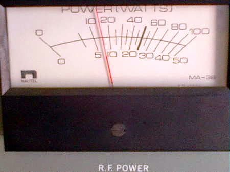
‘OO’ Oshawa NDB
You may recall my blog describing the recent reception of the Oshawa Municipal Airport's NDB, "OO" on 391KHz. The Nav Canada beacon maintenance man, Alex, (VE3GOP) also a Yahoo Group NDBlist member was able to pay a visit to the beacon on Friday and confirm the reported output power is indeed just 7.5 watts! He even snapped a picture of the power meter ... talk about service!
Little "OO" has also been reported in Europe by none other than Roelof, PAØRDT, while using one of his own small active whips. I think this illustrates the remarkable propagation that can, and often does, take place below the broadcast band, even with a less than optimum antenna system ... good news for those planning a 630m backyard antenna installation!
 |
| courtesy: A. Wiecek, VE3GOP |
Little "OO" has also been reported in Europe by none other than Roelof, PAØRDT, while using one of his own small active whips. I think this illustrates the remarkable propagation that can, and often does, take place below the broadcast band, even with a less than optimum antenna system ... good news for those planning a 630m backyard antenna installation!
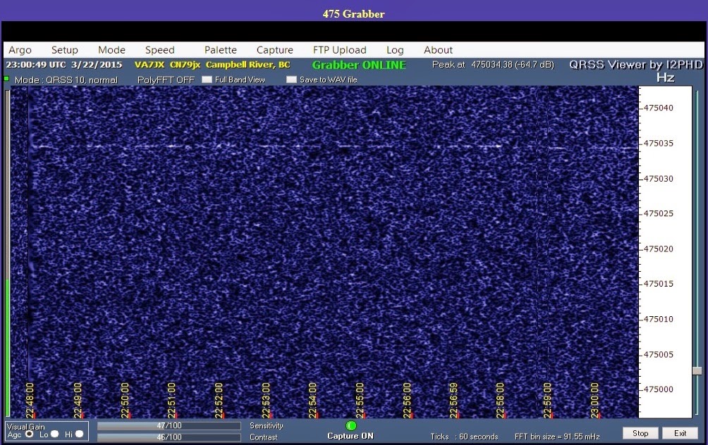
A 630m QRSS Test
A few days ago, the power of the slow speed QRSS mode was nicely demonstrated by Mark, VA7MM (Coquitlam, BC) and Jack, VA7JX (Campbell River, BC, on Vancouver Island).
Mark was transmitting on 630m at a power of just 144mW output, while Jack was receiving on his normal 630m inverted 'L'. Mark tried various QRSS speeds ranging from QRSS3 (3 second 'dits') to QRSS60 (60 second 'dits'). One can clearly see the difference between the three speeds.
Going from the relatively slow CW rate of 6 WPM to just QRSS3 alone, produces a healthy 12db increase in signal level. Going from there to QRSS10 produces another 5db, while going all the way to QRSS60 produces a whopping 24.8db over 6 WPM CW! The trade off, of course, being the amount of time it takes to send the needed information.
In practical terms, contacts can be made relatively quickly at both QRSS3 and QRSS10. After that it becomes a bit of a chore as conditions need to be very stable for long periods of time ... as well, you'll need several hours to complete a two-way exchange.
This is over a 120 mile (192km) path but what is remarkable is the rugged nature of the path as shown here:
Although mostly over water for the second portion, the initial launch of Mark's signal is into a hellish 60 mile path of rugged coastal mountain peaks, with most of them in the 3,000 - 4,000 foot range! If this is an all groundwave path, and I suspect that it may be, it surely demonstrates the amazing groundwave capability of 630m. If there were any skywave involved, I would expect to see some fading on the signal path ... but the QRSS60 signal looks rock-solid and fade-free.
I should add that Mark's transmitting antenna is very minimal at the moment, consisting of an 80m dipole fed as a vertical 'T', tuned but not impedance-matched and ... no ground radials. Pretty remarkable actually.
Mark was transmitting on 630m at a power of just 144mW output, while Jack was receiving on his normal 630m inverted 'L'. Mark tried various QRSS speeds ranging from QRSS3 (3 second 'dits') to QRSS60 (60 second 'dits'). One can clearly see the difference between the three speeds.
Going from the relatively slow CW rate of 6 WPM to just QRSS3 alone, produces a healthy 12db increase in signal level. Going from there to QRSS10 produces another 5db, while going all the way to QRSS60 produces a whopping 24.8db over 6 WPM CW! The trade off, of course, being the amount of time it takes to send the needed information.
In practical terms, contacts can be made relatively quickly at both QRSS3 and QRSS10. After that it becomes a bit of a chore as conditions need to be very stable for long periods of time ... as well, you'll need several hours to complete a two-way exchange.
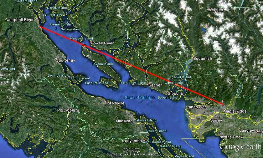 | |
| courtesy: https://www.google.com/earth/ |
 | ||||
| VA7MM - QRSS3 |
 |
| VA7MM - QRSS10 |
 |
| VA7MM - QRSS60 |
 |
| courtesy: http://www.heywhatsthat.com/profiler.html |
I should add that Mark's transmitting antenna is very minimal at the moment, consisting of an 80m dipole fed as a vertical 'T', tuned but not impedance-matched and ... no ground radials. Pretty remarkable actually.
International Radio Restoration Contest
I have recently been made aware of the Socété Québécoise des Collectionneurs de Radios Ancien's / (SQCRA or Quebec Antique Radio Collectors Society) 'Radio Restoration Contest' and have been enjoying some of the published documents describing various refurburations.
Although the group has been sponsoring the refurb contest for over 10 years, this is only the third year that it has been open to international competition. The rules are interesting and are quoted from the SQCRA website:
" ... participants have one year to restore a basket case radio (the worst it is at start, the more points are awarded for the difficulty). Pictures must be taken before the restoration starts and at all steps of the process. One year later, the participants present their work to the international panel of judges. Pictures taken during the process will help judges better understand the challenges faced by the participants in order to finish their project.
The clubs that don't have a contest can nominate someone or make a group effort to represent their club at this contest.
A documented report containing photos and explanations and optionally a video of the working set from each contestant must be submitted to us. Then judgement and results are compiled to determine a winner and two runners up.
A documented report containing photos and explanations and optionally a video of the working set from each contestant must be submitted to us. Then judgement and results are compiled to determine a winner and two runners up.
The criteria's for evaluation are available in this document .
Our goal of course is to promote the conservation of the technological / historical heritage, to motivate our common interest, increase the general knowledge of ancient radio technology, gain restoration tips, increase club exchanges, and see what is done in other clubs."
Each project is judged on three basic criteria: difficulty (condition when found), restoration (chassis, cabinet, components, overall) and functionality when complete.
The present contest has just ended (March 15) but the judge's comments and project writeups from the previous two contests (as well as this year's project writeups) are available for reading ... and they are both instructive and inspirational as I found several new constructive hints embedded in the descriptions.
Particularly interesting to me was the sidebar in the writeup article presented by Gerry O'Hara of B.C.'s SPARC Museum. I have been struggling to develop a method of building this period-correct component for several years and the solution looks elegantly simple!
 |
| courtesy: http://www.sqcra.org/ |
There really is enough reading here to keep one entertained for days but the more I read, the more I want to find another old clunker and bring it back to life ... great stuff!


