Author Archive
 Texas QSO Party Fun
 I spent a few hours, yesterday and today, playing in the Texas QSO Party. As annual QSO Parties go, this one must be one of the best.
 With Texas being such a large state, there seemed to be a correspondingly large amount of activity. As well, Texas is a nice single-hop from here on HF and most signals, even from the numerous mobiles, were loud.
I entered in the low-power, single- operator, CW-only class and without spending huge amounts of time, ended up with 185 contacts in 117 counties. There was a very active fleet of mobile operators as well, moving from county to county and sometimes setting-up on county borderlines to provide two, three or even four counties at a time. Thanks to the dedicated mobilers ... you fellows really add a lot of interest to the contest.
Mobile stations also provide extra 'bonus' points, with 500 additional points gained each time you work the same mobile in 5 different counties. Two of them were worked in more than 15 counties, while five were worked in 10 counties. Two were worked in 9 counties, missing the extra thousand points by one more from each.
My weekly QSO Part activity has been a good way for me to ease back into contesting and an aid in improving my ear-brain-keyboarding skills ... it's been helping a lot. One area that doesn't get a lot of practice is in the 'run' mode, since most of these QSO party contacts are in the 'search and pounce' (S&P) mode. Hopefully something will come up soon where I can get more 'run' practice as this requires a higher level of alertness compared with S&P. In reality, either mode is a great way to keep your CW skills honed.
The old laptop, running Windows XP, continues to work well as does the N1MM logging software driven by the K1EL USB keying interface. Further scrubbing of the laptop's unneeded files and start-up programs has sped boot-time to about 90 seconds. Quite an improvement over the eight minutes it was taking before tackling the cleanup!
If you are interested in getting started in contest work, or getting back into it, the WA7BNM Contest Calendar is probably the best source of information ... descriptions of all of the major contests (and some not so major), as well as links to contest-sponsor pages, may be found there. As well, the same site provides the '3830' board, a place where contesters can share their claimed score totals and discuss the event immediately following a contest. It's always fun to see how you compare with other submissions in the same category.
‘Tin Whiskers’
 I've just recently read of a phenomenon that I had never heard of before this week ... "Tin Whiskers". Tin whiskers are hairlike crystalline structures that can grow from tin surfaces and have the potential to wreak havoc on modern electronics.
Ever since the European RoHS (Restriction of Hazardous Materials) implementation, most manufacturers have been forced to switch to lead-free solder. It seems that lead, when combined with tin, inhibits the growth of tin crystals. Although tin whiskers have been around for many years, it is just since the switch to lead-free solder that their impact on circuit boards (particularly with SMD sizes) has been garnering a lot of attention. Even the military, which has always demanded a higher standard for its components and circuit fabrication, is worried. With almost everything, from alarm clocks to aircraft, reliant on electronic circuit boards, are we awash in a sea of electronic ticking time-bombs? Some experts believe that we are.
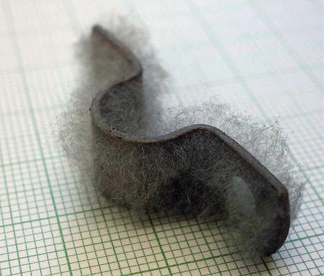 |
| courtesy: https://en.m.wikipedia.org/ |
An article in Aviation Today reports:
It’s rational to ask, after a few years of RoHS policy in force, does this effect ever really cause any problems? As it happens, yes, and some examples are so spectacular that it’s amazing they have not reversed the policy for RoHS. In Europe, the most impressive example was $1 billion recall of Swatch watches from Switzerland, as the use of lead-free solder caused a roughly 5 percent watch failure rate in 2006. The “solution” to this problem was yet another rule exemption, and lead was again used in Swatch construction. A real RoHS policy triumph there.
John Keller, Editor in Chief of Military & Aerospace Electronics magazine reported in a 2005 article that:
Reports indicate that six satellites sustained partial or complete loss due to tin whiskers. These involved Galaxy-3, Solidaridad 1, Direct TV3, and HS 601 satellites built between 1998 and 2002. Problems also have been reported with the F-15 jet fighter radar, the Patriot missile, and the Airborne Warning and Control System (AWACS) aircraft.
One prominent manufacturer, Apple, has been using lead-free solders since 2004, reportedly, without any issues. As noted by Kurt Jacobsen, author of "Within A Whisker of Failure" (published in The Guardian):
Perhaps manufacturers haven't developed an "experience base", or perhaps it isn't registering as a problem. Many customers will probably chalk failed devices off to their own isolated tough luck, when the cause might really have been microscopic whiskers inside their machines.
And Bob Willis, Technical Director for the Surface Mount and Related Technology Group in the UK mused:
Overall, was it sensible to go lead-free? "I would say no," ... Earlier obsolescence means more discarded devices. Critics argue that substitutes are more toxic and energy-wasteful than the lead they replace - and that lead doesn't leach from circuit boards, because it doesn't migrate as lead in paint or petrol does.
Well worth reading and perhaps one of the best summaries of the dilemma can be found in "Death By Tin Whisker" by Walter Shawlee:
This is clearly a problem that has to be addressed for the avionics industry sooner rather than later. Either a clearly worded exemption from lead use is required, or the frankly ineffective removal of lead from electronic assembly construction rule should be abandoned. This misguided policy has introduced a random failure mode into every item now being made under these standards or with RoHS compliant parts, a simply unacceptable risk for all involved. Plus, the ridiculously small (2 percent) targeted lead-use area fails utterly and completely to address the very real concerns of lead toxicity in the environment. Clearly, all of these issues are something worth thinking about, and their impact on our industry and all of us is significant if no useful action is taken.
Although this is all new to me personally, perhaps this is old-hat by now, since the problem has been around for the past few years. Maybe a viable solution has been found already or will we see the introduction of lead into solder once again? I also wonder about the millions of life-critical circuit boards already in place that are, at this moment, quietly growing 'tin whiskers'.
Lightwave Scatter Planning
Over the past few days I've been trying to figure out some possible pathways that might be covered when transmitting from home.
The only real directions that I can go any distances are towards the southwest and to the southeast because of two large hills (500' and 900') to the south.
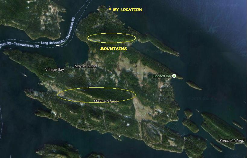 |
| courtesy: https://www.google.ca/maps |
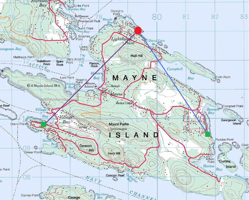 |
| courtesy: http://www.jeffstopos.com/ |
The challenge will be to put a signal over this 500' hill, about 1.5 km to the south ... I'll need to go around it on either side or over the top. Going around it at its edges will allow me to keep the light beam on a fairly low angle.
The main obstacle is my lot ... it is heavily treed in these directions and aiming would have to be too high of an angle to get over the trees. I do however, have one small gap between the trees which has turned out to be close to the right bearing (220 degrees) for the southwest test. For this, I can set the transmitter on my back sundeck and shoot through the gap without bothering anyone. For the southeast shot, or one over the top,of the hill, I'll need to move the transmitter two lots to the east of me, and use the neighbour's clear view of the hill.
This should work out OK, as the neighbour spends the winter in Boston and the house is vacant ... but the outside power sockets are alive. This path though, has me shooting across a small bay and above several houses. Most are summer residents only but there are a couple that are permanent. I'll need to contact them and give them a 'heads-up' before I run any tests, so they don't call the RCMP!
The June 2014 edition of Radcom has an inspiring article by G3XBM, "Over The Horizon At 481THz", where Roger describes his early clear air scatter tests and excellent results over an 8.5 km path. This is a very impressive distance considering the small LED transmitter and 4" magnifying-glass lenses used.
Unfortunately, the distances here, on both paths, are not very much ... about 5 km. I'm fairly limited to how far I can go here on the island. I'd be very happy to cover this comparatively short distance and a lot will depend on being able to keep a low enough angle and still get over the hill.
With the right weather, I may start as one reader has suggested, with a short almost vertical incidence shot and set up a few blocks away to test out the system.
CLE 198 Results
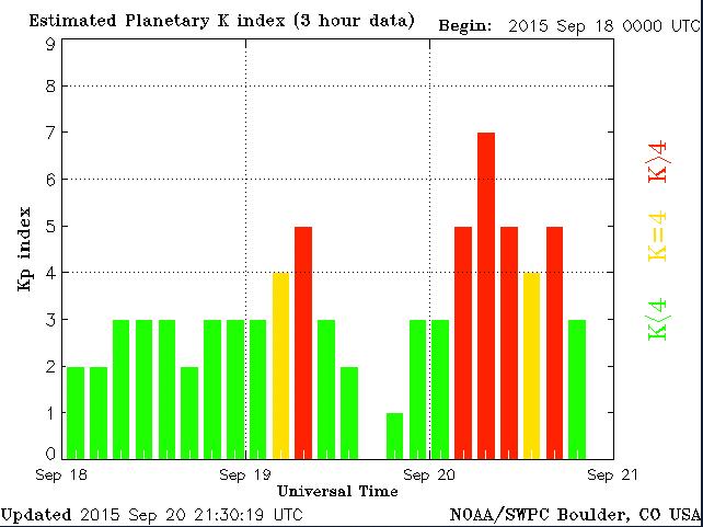 |
| courtesy: http://www.swpc.noaa.gov/ |
For those looking to log Hawaii on the NDB band, 'POA' on 332 kHz is a good bet as it had a strong signal here on all three nights and was heard shortly after sunset in Hawaii.
------------------------------------------------------------------------------------
DD UTC kHz Call mi New Location
--------------------------------------------------------------------------------
19 11:00 323 HJH 1393 Hebron Municipal Apt, NE, USA
19 10:00 325 YJQ 312 Bella Bella (Campbell Island), BC, CAN
19 12:00 326 XJ 522 Fort St. John, BC, CAN
19 09:00 326 MA 1594 FARLY - Midland, TX, USA
20 04:00 326 FO 1531 'Riply' Topeka, KS, USA
19 10:00 326 DC 131 Princeton Municipal Apt, BC, CAN
19 12:00 328 LAC 133 'Lacomas' Fort Lewis, WA, USA
19 12:00 328 5J 564 Coronation, AB, CAN
20 05:00 329 YHN 1730 Hornepayne, ON, CAN
19 12:00 329 YEK 1414 Arviat, NU, CAN
19 12:00 329 X2 590 Athabasca, AB, CAN
19 12:00 329 TAD 1240 Trinidad - Hoehne, CO, USA
19 10:00 329 PMV 1437 Plattsmouth, NE, USA
19 12:00 329 PJ 920 Robinson (Whitehorse), YT, CAN
21 09:00 329 HMA 1851 Hondo Municipal Apt, TX, USA
19 08:00 332 XT 442 Terrace, BC, CAN
19 08:00 332 XH 565 Medicine Hat, AB, CAN
19 08:00 332 WC 25 White Rock (Abbotsford), BC, CAN
20 04:00 332 VVV 1280 Ortonville Municipal Apt, MN, USA
19 08:00 332 POA 2681 Pahoa - Hawaii Island, HWA
20 05:00 332 FIS 2794 Fish Hook - Key West, FL, USA
19 08:00 333 STI 540 'Sturgeon' Mountain Home, ID, USA
19 08:00 334 P2 514 Wetaskiwin, AB, CAN
------------------------------------------------------------------------------------
As usual, all stations were heard using the Perseus SDR.
Hopefully CLE 199 will see the return of quieter band conditions and better propagation ... if the sun can calm down long enough.
Drawing PCBs With ‘MS Paint’
I recently had an inquiry about using 'MS Paint' for drawing PC board layouts. Although there are several freeware programs available for designing and drawing PC layouts, the ones I have tried had onerous learning curves. I also found that unless I was designing boards fairly regularly, I would have to go back and re-learn many of the functions each time I used the program. If you are regularly making a lot of boards, then these programs are certainly the way to go as they are packed with every feature you might need.
On the other hand, MS Paint meets all of my requirements and is simple to use ... I like simple. Although some might turn up their noses at MS Paint, I have found it to be a powerful and underestimated software tool. Here are some of the things that you might want to remember if drawing a PC layout with 'Paint'.
1. Take the time to read the built-in HELP and USING files. It doesn't take long to learn all of the functions along with some of the shortcuts.
2. Always draw with the IMAGE ... DRAW OPAQUE function turned off (unchecked). Do this first. This way, lines can go as close as you want without any blocking or overlapping. Try it the other way and you can see what happens.
3. If you are working with IC's, take the time to make a 'master' pattern that can be saved and copied anytime that you need it. A 16-pin layout can by used for 14 and 8 pin IC's by copying and pasting it and then erasing the unwanted pins. I can send you one via email if you contact me.

4. Similarly, once you have established the correct pad spacing for certain capacitors or resistor sizes, copy and save them for future use. Finding the correct spacing will require a few trial printouts so you can measure the exact gap.
5. For detailed work, use the VIEW ... ZOOM...CUSTOM function to magnify the layout. This also allows you to use a grid if you find this helpful.
6. Never SAVE your layout while in ZOOM mode as you can't go back to the original size when you re-load your plan. I learned this the hard way.
7. For drawing perfectly straight lines, squares or round circles, hold the SHIFT key down when drawing the element.
8. For large areas of copper (groundplanes), outline the area then choose the FILL symbol to create the area.
9. With a little planning, you can almost always avoid jumpers to make a crossover connection, unless your circuit is very complex.
10. When you make a mistake, just use the EDIT ...UNDO command. You can go back several steps with this helpful function.
11. I will often draw a thin line between to pads to see if they are on the same level ... and then UNDO the line once I have checked.
12. Always SAVE your layout as a Monochrome Bitmap with the FILE ... SAVE AS function. Using some of the other modes will create less than solid blacks and some random pixels that can lead to etching problems.
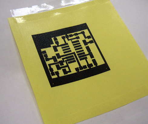
13. If using the 'toner iron-on' method of etching, set your printer options to the highest resolution (mine is 1200 dpi) and then choose the darkest 'print' option. You want as much toner thickness as possible. Note that this method works only with laser / toner printers and not the ink-jet / bubble types.
14. For the iron-on transfer paper, I have had good success with the shiny yellow transfer paper widely available on E-Bay, usually with free shipping. I get the best results when pre-heating the PCB in the toaster oven before ironing-on the pattern ... not too hot to touch however.
If you just build the occasional PC board, you might find using MS Paint worthy of a try. It has been meeting my needs for many many years and once you have done a few, unlike some PC software, it doesn't take long to build a new board without having to learn how to use it all over again.
Lightwave-Portable Progress
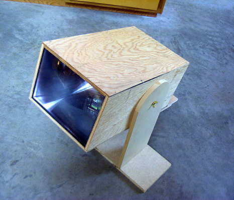
On Tuesday, I completed the plywood enclosure for the new portable lightwave receiver and mounted the optics and the electronics. My plan is to use this here on the island for some clear-air scatter / cloudbounce tests, once suitable listening locations are determined.
As with my main system, I used a homebrew mount capable of movement in three directions.
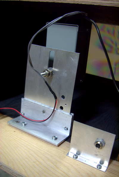
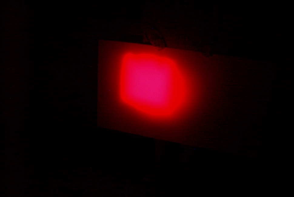
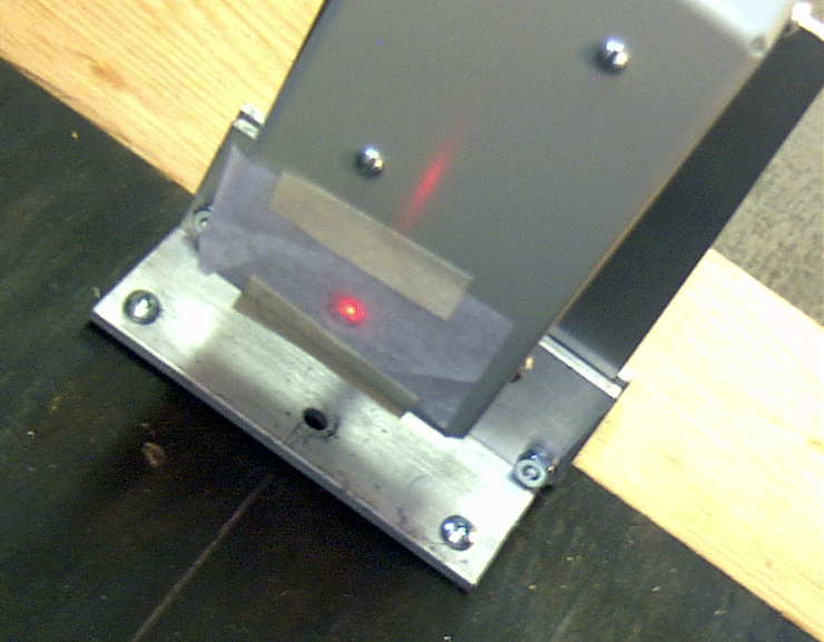
The photodiode needs to be mounted precisely at the focal point of the fresnel lens, and all three directions need to be juggled for correct alignment. Shown below is the setup used on the shop floor for alignment. The signal source is a 1W red LED about ten feet away.
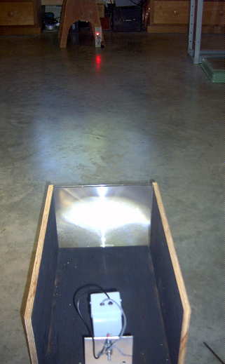
I covered the photodiode with a small piece of paper which made it a lot easier to find the point of sharpest focus. Once this had been found, everything was tightened and, hopefully, locked into position.
I then constructed a simple mount which allows the receiver to be tilted in altitude so it can be set to point at the desired region of sky. Once this was done, there was nothing else I could do but wait for darkness, so that the receiver could be tested.

The fresnel lens used was purchased locally for just $5, so I had my suspicions regarding its optical quality. As well, it is 20% smaller than the bigger lens used in the main lightwave system. The bigger lens is 650 sq.cm compared to the inexpensive 'page-reader' lens of 530 sq.cm. The 2mm thick rigid plastic lens is an 'Enkay 2950-C'. The larger lens has a focal length of 20cm while the page reader has a focal length of 45cm. This gives them 'f' numbers of .78 and 1.6 respectively.
Once it was dark enough, I took the receiver to the ocean side of the house and sat down with the receiver. From here I have a clear view of the mainland coast, on the other side of Strait of Georgia. The nearest point of land on the other side of the Strait is about 20km.
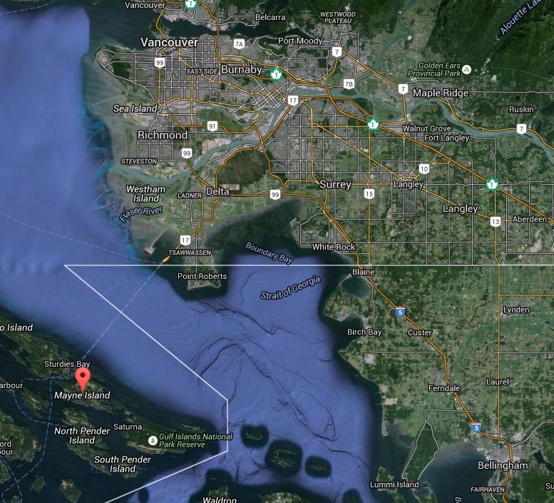 |
| courtesy: https://www.google.ca/maps/ |
To hear similar signals, recorded on my first receiver, go to the links at the bottom of this blog from 2014/08.
The next task will be to determine suitable listening locations here on the island. Unfortunately, the island is dominated with two high (600'+) peaks, one right behind me to the south, which will make it challenging to get a signal from one side to the other. Hopefully I can find a clear spot somewhere that will allow me to shoot a signal over the top ... and of course, the fall weather must co-operate.
 |
| courtesy: https://www.google.ca/maps/ |
Hunting For NDBs In CLE 198
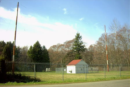 |
| 'WC' - 332 kHz White Rock, B.C. |
A list of all of the North American targets in this range can be found in the RNA database, while targets for European DXers will be found here ... specify the frequency range wanted and check 'show all results'.
An excellent target for this CLE is 'WC' (332kHz) shown here. Its 25W signal gets out very well and has been heard as far as Texas. It is unusually-located in the middle of a quiet residential street, nestled between homes on each side.
From CLE coordinator Brian Keyte (G3SIA) comes the following reminder:
Our next Co-ordinated Listening Event is less than a week away.
It is an ideal one for new listeners as well as for regulars:
Days: Friday 18 September - Monday 21 September
(a week earlier than originally planned)
Times: Start and End at midday, your LOCAL time
Range: 320.0 - 334.9 kHz
It's straightforward - just log the NDBs that you can identify having their
nominal frequencies in the range, plus any UNIDs that you come across
there. We last concentrated on these frequencies during CLE183 in June
2014.
We'll be near the DGPS beacons range and some of us, especially in North
America, may hear a few. I suggest that we don't seek out or report these
in this CLE.
Send your CLE log to the List, if possible as a plain text email and
not in an attachment, with CLE198 at the start of its title.
Show on EVERY LINE of your log:
# The Date (or day 'dd') and UTC (the day changes at 00:00 UTC).
# kHz - the beacon's nominal published frequency (if you know it).
# The Call Ident.
Please show those main items FIRST on each line, then any optional details
such as Location, Offsets, Distance, etc.
If you send interim logs, do make sure that you also send a 'Final' log
containing all your loggings. As always, please make your log useful and
interesting to everyone by including your own location and brief details
of your receiver, aerial(s) and any recording equipment that you used.
You can find CLE-related information from the CLE page,
http://www.ndblist.info/cle.htm , including access to the seeklists
that have been made for the event from REU/RNA/RWW.
(NB: To also see a MAP of the seeklist NDBs around you, just change
'List' to 'Map', select 'All Results' and uncheck 'Clustering')
Good listening
Brian
----------------------------------------------------------
From: Brian Keyte G3SIA ndbcle'at'gmail.com
Location: Surrey, SE England (CLE co-ordinator)
----------------------------------------------------------
(Reminder: You could use any one remote receiver for your loggings,
stating its location and owner - with their permission if required.
A remote listener may NOT also use another receiver, whether local or
remote, to obtain further loggings for the same CLE).
These listening events serve several purposes. They:
- determine, worldwide, which beacons are actually in service and on-the-air so the online database can be kept up-to-date
- determine, worldwide, which beacons are out-of-service or have gone silent since the last CLE covering this range
- will indicate the state of propagation conditions at the various participant locations
- will give you an indication of how well your LF/MF receiving system is working
- give participants a fun yet challenging activity to keep their listening skills honed
Final details can be found at the NDB List website, and worldwide results, for every participant, will be posted there a few days after the event. If you are a member of the ndblist Group, results will also be e-mailed and posted there.
The very active Yahoo ndblist Group is a great place to learn more about the 'Art of NDB DXing' or to meet other listeners in your region. There is a lot of good information available there and new members are always very welcome.
If you are contemplating getting started on 630m, listening for NDBs is an excellent way to test out your receive capabilities as there are several NDBs located near this part of the spectrum.
You need not be an ndblist member to participate in the CLEs and all reports, no matter how small, are of much value to the organizers. 'First-time' logs are always VERY welcome!
Reports may be sent to the ndblist or e-mailed to either myself or CLE co-ordinator, Brian Keyte (G3SIA), whose address appears above.
Please ... give the CLE a try ... then let us know what NDB's can be heard from your location! Your report can then be added to the worldwide database to help keep it up-to-date.


