Author Archive
 CW decoder – The Arduino
 This is arguably the simplest part of the project. As mentioned Budd Churchward had created a series of videos on how he wrote the Sketch, created a PCB and published his code. (Budd’s Sketch is available here)
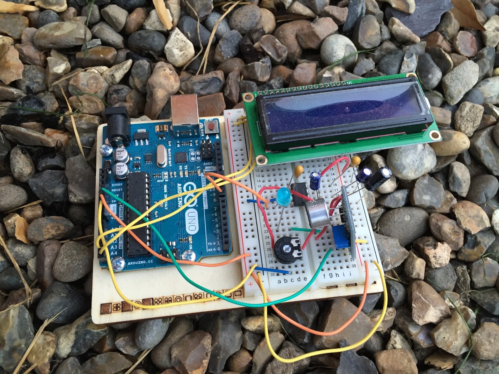
CW decoder – The electronics

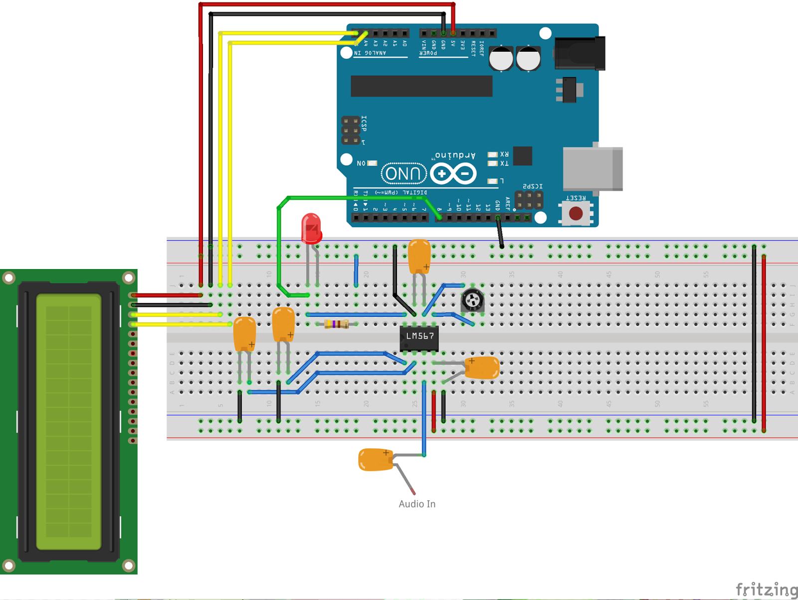
CW decoder – The electronics
CW decoder – Introduction
 If you do follow me on twitter (and if you don’t – you really should) you will have no doubt seen my recent tweets about constructing a CW decoder. After a number of retweets, and favorites from other very interested hams – I did promise that I would collate all my knowledge into a blog posts and share the details with you all.
So, for those who have not been following me on twitter – here is the sales pitch. I recently started looking at some projects that I could get my Arduino Uno involved in with the radio hobby. I have a number of reasons why I want to combine radio, Arduino and some electronics – more about this later.
I stumbled across a video on YouTube where Budd Churchward showed his Arduino copying and decoding CW straight off the HF band and at a reasonably high speed. I ventured further and wanted to know what electronics Budd was using to achieve this excellent little project.
I used the limited shared knowledge and discovered that the electronics is basally a LM567 – Tone decoder chip that (I have since discovered the chip is used in the ARRL book for Arduino Projects) I discovered takes an audio input and converts this to a HIGH / LOW output suitable for the Arduino to use as a signal for decoding.
Finding a suitable project for the LM567 and trying to work out how fellow constructors had configured their LM567s was not an easy task. This did indeed take quite a lot of chasing and head scratching. I will go into more technical detail on the next post – but for the reason why I wanted to complete this ? very simple. I w
ant to create a project that would “inspire” young electronically minded students that might have an interest in radio – (i.e the morse code) some coding experience and some construction / electronic interest. This project covers all 3 areas, and only lightly covers each subject area.
In the next post – I show the LM567, the schematic and give you the list of parts required.
CW decoder – Introduction
If you do follow me on twitter (and if you don’t – you really should) you will have no doubt seen my recent tweets about constructing a CW decoder. After a number of retweets, and favorites from other very interested hams – I did promise that I would collate all my knowledge into a blog posts and share the details with you all.
So, for those who have not been following me on twitter – here is the sales pitch. I recently started looking at some projects that I could get my Arduino Uno involved in with the radio hobby. I have a number of reasons why I want to combine radio, Arduino and some electronics – more about this later.
I stumbled across a video on YouTube where Budd Churchward showed his Arduino copying and decoding CW straight off the HF band and at a reasonably high speed. I ventured further and wanted to know what electronics Budd was using to achieve this excellent little project.
I used the limited shared knowledge and discovered that the electronics is basally a LM567 – Tone decoder chip that (I have since discovered the chip is used in the ARRL book for Arduino Projects) I discovered takes an audio input and converts this to a HIGH / LOW output suitable for the Arduino to use as a signal for decoding.
Finding a suitable project for the LM567 and trying to work out how fellow constructors had configured their LM567s was not an easy task. This did indeed take quite a lot of chasing and head scratching. I will go into more technical detail on the next post – but for the reason why I wanted to complete this ? very simple. I w
ant to create a project that would “inspire” young electronically minded students that might have an interest in radio – (i.e the morse code) some coding experience and some construction / electronic interest. This project covers all 3 areas, and only lightly covers each subject area.
In the next post – I show the LM567, the schematic and give you the list of parts required.
MacLoggerDX
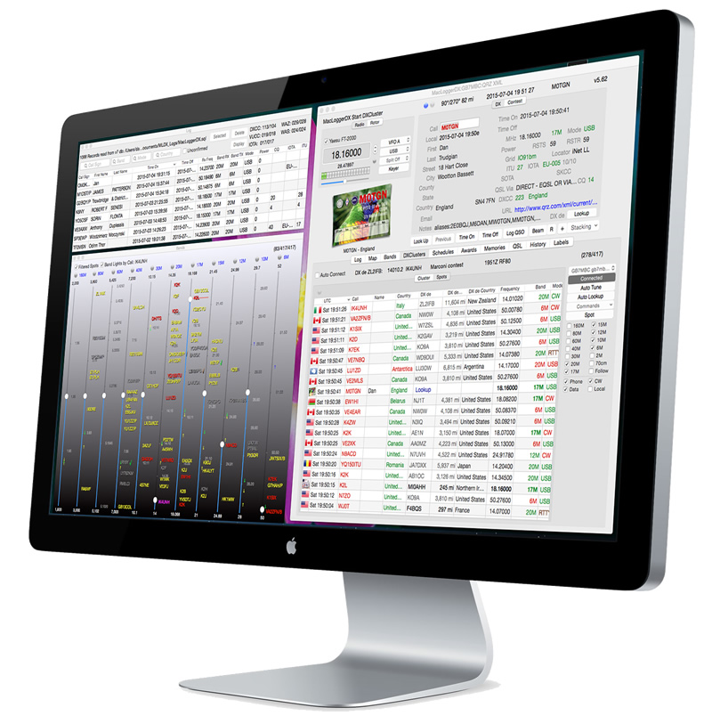 |
| The layout of MacLogger DX on my Mac |
I recently tweeted that I had dropped Ham Radio Deluxe in favour for MacLoggerDX. Amongst the re-tweets and comments i received, Danny (PA3DM) did mention that HRD is not just a logbook, but a full suite of digital modes, rotor and a rig control system. This I completely agree with, and my time using HRD was always a great experience and I would recommend the software to anyone.
My issue with HRD is this. I use a Mac. I transitioned from PC to Mac around 3 years ago, and have been using a Virtual PC to do my PC based tasks (including my day job) and this is the issue. HRD over a Virtual Machine, using RS-232 connectors is unpredictable, slow and frankly unusable. Its not the fault of HRD, nor is it the fault of the Virtual Machine, The RS-232 – USB connectors. It’s a combination of all the elements tethered together that makes the experience unusable.
So the solution ? well its not a solution to be fair. It’s a compromise. Its not HRD, its not an all in one solution, its a log book that can use the radios VFO, the rotor and DX cluster all together. That is basically what I used HRD for. And on the odd occasion I did venture into digital modes.
I will complete a review of MacLoggerDX in future posts, but for now I thought I would explain my rationale of making the switch. So far, so good.
MacLoggerDX
|
| The layout of MacLogger DX on my Mac |
I recently tweeted that I had dropped Ham Radio Deluxe in favour for MacLoggerDX. Amongst the re-tweets and comments i received, Danny (PA3DM) did mention that HRD is not just a logbook, but a full suite of digital modes, rotor and a rig control system. This I completely agree with, and my time using HRD was always a great experience and I would recommend the software to anyone.
My issue with HRD is this. I use a Mac. I transitioned from PC to Mac around 3 years ago, and have been using a Virtual PC to do my PC based tasks (including my day job) and this is the issue. HRD over a Virtual Machine, using RS-232 connectors is unpredictable, slow and frankly unusable. Its not the fault of HRD, nor is it the fault of the Virtual Machine, The RS-232 – USB connectors. It’s a combination of all the elements tethered together that makes the experience unusable.
So the solution ? well its not a solution to be fair. It’s a compromise. Its not HRD, its not an all in one solution, its a log book that can use the radios VFO, the rotor and DX cluster all together. That is basically what I used HRD for. And on the odd occasion I did venture into digital modes.
I will complete a review of MacLoggerDX in future posts, but for now I thought I would explain my rationale of making the switch. So far, so good.


