Author Archive
 Been travelling

View when flying from Vancouver, BC to Seattle, WA
I have spent this week in Seattle, WA on business. Did not have much time for radio but I have been using the DVAP dongle and been linking into the repeater back in Ottawa either directly or via REF016B.
The DVAP works well whilst travelling. I even used it to link through to talk to the students at the Carleton University Amateur Radio Club. I could then chat to them as they were working on building a PSK31 interface for the FT817. I have also chatted with the locals, some of whom commented that I sound like I am local. I will continue packing the DVAP with the IC-91AD in future. By the way, there was no trouble taking the HT in my hand luggage on the plane, no questions at Ottawa or going through customs US Customs at Vancouver. (For those not familiar flying from Canada to the US it is not unusual to pass through US immigration/customs in a Canadian airport so you land as a ‘domestic’ flight in the US).
Today I had a little time to visit a hardware store called Hardwicks that was close to the hotel. This reminded me of the old ironmongers store that was in the village I grew-up in, in Lancashire, UK. however, Hardwicks was about 5 times bigger. Great to wander around and look at the range of tools and hardware.
I also visited a RadioShack store (in Canada now called the Source) and was pleased to see some drawers with components in. At least you can still get a voltage regulator on the high street!
Travelling back today.


![]()
Two biography books for engineers

The F-117 Nighthawk, designed by the Lockheed ‘Skunkworks’. (Image in public domain from Wikimedia Commons)
I have just finished reading ‘Skunkworks’ by Ben Rich and Leo Janos and it should be one of those books that engineers, students of engineering and those that like technology should read. The book details the secret Lockheed Martin aircraft design branch, set up and run by Kelly Johnson, which became known as the ‘Skunkworks’. Out of this special projects group came the F-104 Starfighter, the U-2 spy plane, the SR-71 Blackbird and the F-117 Nighthawk (also called the stealth fighter), amongst other aircraft. The book starts out with the development of the Nighthawk which was developed by a team led by Ben Rich, who replaced Kelly Johnson as the head of the Skunkworks. After telling that story of the stealth fighter development over the first few chapters it goes back in time to when Ben Rich first joined the special projects unit and how he became involved in the development of some of the most advanced military aircraft of the 20th Century. The book is an exciting insight in to how advanced engineering projects can be run. ’Skunkworks’ was allowed to be free from the usual corporate bureaucracy and therefore it could move quickly in development. There was also a philosophy of using off-the-shelf parts as much as possible, including engines, so reducing delays from manufacturing new parts that would then need to be continued to be produced. Although this philosophy was challenged with the development of the Blackbird which was designed to achieve Mach 3 speeds and so needed to be constructed with large amounts of titanium.
Combining details of how the planes were developed, the challenges and uses of the planes, as well as some insight into management styles and how to obtain multimillion dollar contracts make the book extremely interesting. When you read about the uses of the U-2 in the Cuban Missile Crisis, the shooting down of Gary Powers, and the use of the F-117 in Iraq you can see these aircraft had influencial and important roles in the the Cold War period and beyond. It was also interesting to read about the irony of how a relatively obscure Russian paper on electromagnetic theory lead a young mathematician at the Skunkworks to propose how they could devise an aircraft that was almost invisible to radar.
Check out your library or bookstore to find a copy of ‘Skunkworks’ and read about engineering at its best. To illustrate the performance of the U-2 here is a video from the BBC where presenter James May gets a flight in the two seater version of the U-2. You can see how the U-2 could fly so high it was out of range of fighter jets and missiles (although there is a report of an English Electric Lightning F3 intercepting one at 88,000ft during a NATO excercise in 1984).

Onto the second engineering biography book to read. This is ‘iWoz’ by Steve Wozniak and Gina Smith, which I read a year or two ago and should have written about sooner. This is the story of Steve Wozniak, co-founder of Apple and the real technical brains behind the development of the first Apple computers, including the massively successful Apple II. This is a very personal account, and more like a traditional autobiography than ‘Skunkworks’, but there are some interesting insight into how ‘the Woz’ come come up with the design for computers that effectively started the microcomputer revolution. It is fascinating to read how in high school he collected minicomputer manuals and with the help of catalogues and datasheets of newer components he would redesign the circuitry of those computers to use fewer components. Also interesting is his interest in using components in more than one way on the same board. Here you can see the real engineering genius coming through. Below is a short clip of Wozniak talking about the ‘economy’ of the design of the Apple II at book signing event for ‘iWoz’.
Summer is not far away so chase down one or both of these books for your Summer vacation. Lots of engineering inspiration is contained within the both books.
Small loop antenna for HF listening
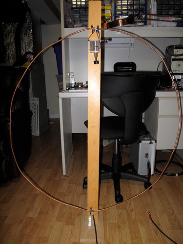
I built this antenna a few years ago and it is about time I posted details about it on this blog.
This is a small loop, that is the length is ≤0.1 of a wavelength, and designed for receive only, not transmitting. The loop is a little more oval than round with the narrower diameter being 36″ and the wider diameter being 40″. A transformer is used to collect the signal and pass it via coax to the receiver. The antenna shown and described here tunes from around 3 MHz to 18 MHz. So it covers 80m through to 20m and of course the broadcast bands in between those frequencies too.
The schematic of the loop is shown below.

Schematic of the small loop antenna
The main loop is composed of ¼” copper tubing (available from hardware and plumbing stores). The advantage of this type of tubing is that is easy to bend into a set shape and it maintains that shape with just a few fixing points. If a wire loop was to be made it would require some sort of frame to retain the loop shape.
The capacitor is a variable capacitor from a receiver. I have not measured the capacitance but I suspect both sections together give a maximum of 300 to 400pF. To increase the range of the tuning of the loop I included a switch to allow either one or both of the dual stage capacitor to be included in the loop. The picture below shows the top mounting of the loop, the variable capacitor and the switch. To make easy connection to the capacitor, the copper was squeezed closed at the ends and holes were drilled for bolts. Ring or spade-end connectors can be used to connect wires from the capacitor to the copper tube, and held in place with nuts and bolts.
Note that the copper ends of the loop should not contact each other. They are close in my loop, because of the cable tie mountings on the pine wood, but they do not touch. Electrical connectivity is through the capacitor. To prevent any ‘hand capacitance’ effects when tuning (and hence tuning issues) I added a non-conducting shaft on the capacitor (you can see the brass shaft connector). In my loop the two capacitor sections are joined in parallel to increase the capacitance. The switch can switch out one section, so decreasing the minimum capacitance and increasing the upper frequency that can be tuned. A single stage capacitor, without a switch, will do fine, but the higher the capacitance the better.
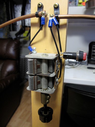
At the opposite end of the loop a T50-43 toroid has been threaded onto the copper tube. The toroid has five turns of enameled wire wound on it and it slides easily over the copper. The copper loop now makes one turn on the loop and the five turns of wire on the ferrite toroid makes the transformer (as shown on the schematic). This arrangement can be seen below.
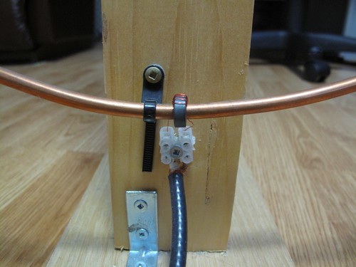
The enameled wire ends have had the enamel removed (only the ends) and have been tinned with solder before inserted into the electric wire block, which allows connection to the RG-58 cable. At the end of the cable add whatever connector you need for your receiver. The photograph also shows the simple L bracket arrangement for holding the pine plank upright on a simple plinth (a small piece of off-cut maple) large enough to stop the loop from toppling over..
The use of the electric connector block is not ideal I find (the enameled wire is too thin) and in future I will probably make something suitable out of some unetched copper circuit board and solder the wire and coax directly to the board.
I am sure there is room for experimentation with the type of mix of the toroid, as well as the number of turns of the enameled wire. My loop worked satisfactorily so I left it as it is.
How does it perform? Well I find it always surprises me how well it works for about 10ft of copper tube in a loop, a capacitor and a transformer. I use this in my basement and can easily tune in stronger stations on the bands. The high Q of small loop antennas rejects strong out of band stations that can bleed-through in more conventional random wire or even dipole antennas, so improving reception performance. When using the antenna you must tune to the frequency or band of interest and then adjust the loop’s capacitor to tune the loop to the same frequency. You will hear either a rise in signal strength of a station or background noise if there is no station on frequency. It is simple to use and it is surprising how it can increase the received signal.
Below are a few recordings made using the loop antenna. The receiver was the old but excellent Yaesu FRG-7, which for the purpose of this demonstration serves well as a general good receiver, although as you will hear the filtering is wide (‘barn-door’ wide springs to mind). For each of the recordings I tuned the receiver to the required frequency and adjusted its pre-selector for maximum signal. What you will hear in each case is the signal and then I will detune the loop one way, then tune it back through the peak to the other side and then returning to the peak of the signal. Recordings were made with an MP3 recorder place in-front of the receiver’s speaker, so you hear what the listener would hear. You should remember this is a 10ft circumference loop in my basement, NOT 100+ft of wire 50ft off the ground.
Small loops are directional to the signal source so if you use one you should experiment by turning it. It may be the HF frequency, or the fact that my antenna is below ground level, but I have noticed not too much of a difference when the loop is turned in orientation. That said, other small loops I have built for the AM broadcast frequencies, or medium wave, do show a stronger directional nature.
If you want to learn more about small loop antennas I recommend Joe Carr’s Loop Antenna Handbook, published by Universal Radio. That book describes many loops, both large and small and is well worth the read if you enjoy antenna design. This loop design is not from the book, but I used concepts and theory from it. The idea of using the copper tubing and the toroid transformer slid onto the copper was my own, although it may not be a novel idea and could have been reported before.
Let me know with a comment if you build and experiment with such an antenna. Share your findings with other readers.


![]()
Another Blog
Recently, I have created a second blog for D-STAR radio, particularly in the Ottawa area.
You can find it at http://dstarottawa.wordpress.com/ The focus is on D-STAR operations in the National Capital Region and activities of the Ottawa Amateur Radio Digital Group.
My personal blog here continues to be my main blog.


![]()
State of Electronics documentary
Karl Von Moller has been putting together a documentary called ‘State of Electronics – A discussion on the electronics industry in Australia’. This looks like a fascinating and thorough look at the electronics industry in one country. Although focussed on Australia much of the content and discussion will be recognizable and similar to other countries. The final version has not been released yet but it looks like it will be great viewing when it is. Seems it is growing to three parts. I’m looking forward to seeing the finished documentary.
Interesting point to note is the documentary has been filmed using a Canon D5 MarkII digital SLR.
Below is the trailer followed by the ‘roll call’ of people who appear in the documentary.


![]()
‘The 3.11′ a first hand account of the recent earthquake in Japan
Over at “the Brasspounders Cafe” blog, Leo, JJ8KGZ, gives a first hand account of what his experiences were of the earthquake that struck Japan recently. I recommend you read his The 3.11 post.
Our thoughts are with the all the people in Japan as they work to recover and deal with the aftermath and challenges resulting from the earthquake and tsunami. Donations are being sought for that region through the usual organizations, web searches will reveal your national charities or try organizations like the International Committee of the Red Cross or Médecins Sans Frontières. Canadians can use the Canadian Red Cross or see the list at CBC’s website for donations.


![]()
D-STAR one route for traffic into Christchurch, New Zealand

New Zealand flag (from Wikimedia Commons)
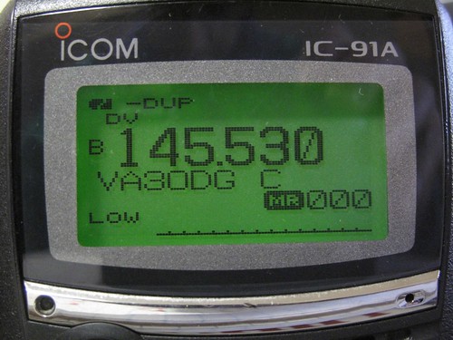
Tonight, before heading home I dropped by the VA3CUA station at the University where I work. I used the Icom ID-1 to link the 1.2GHz module of VA3ODG to reflector REF003C, an Australian reflector. Linked also to the reflector was the repeater ZL1VHD in Auckland, New Zealand. After making a call out on the reflector I had a reply from Marlene, ZL1MYL. We had a nice but brief chat and she told me that there had been messages passed through the Auckland D-STAR repeater for people in the earthquake damaged city of Christchurch. Messages received were being relayed on via other modes on VHF to Christchurch, as that city does not have a D-STAR repeater. The chat with Marlene was short as she had to take a phone call, but I did then talk to her husband Laurence, ZL1ICU.
Later tonight I saw the message from the ARRL that confirms that 2m is being used to support the recovery efforts and currently not HF.
If you have traffic for someone in Christchurch then one possible route in is via the Auckland D-STAR repeater ZL1VHD.


![]()


