Posts Tagged ‘homebrew’
 FOBB Ain’t Broke… SO…
Various QRP related email reflectors and lists are full of chatter about the Flight Of the BumbleBees (FOBB). Comments about the CW being too fast and the weather being too hot at this time of year make it sound like a broken event. IMHO it is far from being broken! It is probably the premier QRP event of the year. And I say, if it ain’t broke… yep, you guessed it, don’t fix it.
Sunday the bands were full of QRP ops, both home based and portable, so the activity really did make a BUZZ despite band conditions that have not been all that helpful to hf qrp contacts. The weather was HOT, but hey, find some shade, altitude or water and go for it. Historically this is the time of year for this event and as others have commented, it keeps our activity up during the summer time when vacations and mowing the grass take their toll on ham radio activity.
As far as fast cw, I’m not fast (not even close hi hi), but it sure is fun listening to the buzz on the bands rather than QRN and a high noise level with only a few weak signals. Certainly I am not a hard core contester. My cw skills are still in need of practice, but isn’t that what events like this provide? I often have to listen multiple times to get the callsign and info but that repetition and practice pushes my speed and confidence level up every time I try. After listening to a fast op several times I have the info I need and then I jump in and have fun making a contact at speeds faster than my comfort zone. Most of us slow guys can send faster than we can receive, right? Come on in, the water is fine, and FUN!
My XYL, Connie and I drove over to Honeymoon Island State Park on the Gulf Coast in Dunedin, Florida. This is a very pretty beach, not overly crowded most of the time and has been one of the top rated beaches in the US for several years. The weather cooperated, there was no sign of the BP oil spill that has run so many tourists to other locations, and we snagged a primo spot to operate right next to the water.The only negative, if you call it that, was that the view was sometimes distracting, but sure was enjoyable.

K4UPG Distracting View from my FOBB 10 Site

K4UPG Honeymoon Island FOBB Site July 2010
My trusty Sierra and Buddistick provided plenty of action so I never switched over to my mini-bac Delta Loop backup antenna. I also stuck to 20m the whole contest since 40m has been in such poor condition here in Florida lately.
One of the great things about these events is the leveling of the playing field. It is fun to contact the guys that write the articles, create the websites and design the equipment that we use for our hobby. My score was modest at 26 QSO’s, 18 Bumblebees and 17 states and provinces but it was one fantastic day of activity for me! Being able to connect with the big guns of QRP was a thrill too!

W8DIZ Stops By to say Hello to K4UPG

K4UPG search and pounce FOBB 10
For me, one of the highlights was when W8DIZ rode over to meet me as I was setting up my site. Diz lives about 3.5 miles from Honeymoon island and is a regular bicycle visitor of this great beach location. I’ve been a customer of his toroid and kit business and have benefited from the info he has shared, not to mention being one of the movers and shakers of the Famous Flying Pigs QRP group. Diz I was honored that you took time out from a busy family day to swing by and say HI! Thanks for the help getting our screen house up too!
Thanks to Adventure Radio Society and the guys that put this event on for all of us. We appreciate the effort it takes and you deserve the very best of 73′s from all of us.
72,
Kelly K4UPG BB #10
Antenna Launcher Revisited
One of my favorite QRP groups is the 4 States QRP Group that sponsors Ozarkcon. Today we had an interesting thread going on their email list concerning slingshot antenna launcher and visibility of the line and sinker.
I’ve been working on that issue for a bit and offered my current solution. Still not 100% perfected, but it is working well now. Here in Florida, the tallest trees are mostly pines and the bark is pretty sticky with sap and lots of crooks and crannies that don’t allow monofilament fishing line to slide as freely as I’d like. I’ve tried the archery reel and slick braided line and although it does slide nicely through the trees, it is much slower and challenging to reel in and also is very prone to tangles and wind knotting which wastes time to untangle. In low wind or super sticky pine trees it is still the best solution.
Below are some photos of my cheapo solution to the slingshot line launcher. A $4 slingshot from Harbor Freight and a 99 cent shelf bracket from Lowe’s are the basic components. One challenge is being able to see where the sinker and line end up after the shot. I tried painting the sinkers, but in tall grass or lots of leafy trees, it did not show up as easily as I would like. The simple solution I found was to use fluorescent plastic surveyor’s tape (also from Lowe’s) to add both vivid color and some motion to help me locate the sinker whether in the trees, air or ground. I’ve also recently switched to red colored monofilament line called Cajun Red Lightning that offers a bit more visibility than clear monofilament.

Here are the basic elements… slingshot, Shelf bracket, spincast reel
If you are looking for an inexpensive simple solution, this might be the answer! Give it a try and let us know how it works for you. Leave a comment or better yet, join the 4 States QRP Group and join the conversation.

Closeup of the mounting of the reel

The assembled launcher — slingshot taped to bracket
End Fed Tuner Success… sort of
Had a good day in the park with Jim K4AHO and Wally KG4LAL. Spent a good bit of time testing a couple tuners for End Fed Half Wave antennas using Jim’s AIM 4170. Wow is that thing a great tool for tweaking antennas! Info overload!
I built an antenna tuner based on AA5TB’s design for an end fed half wave antenna. I am using a 3 ft or so counterpoise on the ground as Steve suggests. On the analyzer in a test lashup it was a bit touchy to hand capacitance but tuned well even up to 21Mhz. Since I am not thinking of backpack size I used a pretty good sized enclosure for it. I am using an air variable 6-160pf cap instead of a polyvaricon like Steve used since space is not a big issue. I also used a T68-6 toroid instead of the T50-2 Steve used.
 When I mounted it in a plastic box the sensitivity seemed to increase. I have not put a LED SWR bridge in the box yet, as I was waiting to see how it worked before adding more variables. Today I was able to put an AIM 4170 analyzer on it and it did tune the antenna… seems that the air variable I used is perhaps a tad small. It is almost fully meshed on 40m cw and on 20m it acts like even at minimum capacitance the sweet spot is very narrow and hard to tune.

Here's the innards
My question(s) are:
1) Is the hand/body capacitance normal? If not, what might cause it to
be so touchy?
2) Would my parts layout be part of the issue?
3) Does the DPDT switch (mini toggle) I added for later use with the SWR
bridge add significant capacitance to the circuit? I was able to match a
21Mhz load on the raw test setup, but not once it is in the box.
4) I have a small bus wire for a ground, do I need to increase that?
5) Is the plastic box the problem? Would it be better in a metal enclosure?
6) Am I asking too many questions? Sorry, this is how I learn. Build,
test, ask… ![]()

SWR bridge I want to use
Thanks for your wisdom and experience on this one.
72,
Kelly K4UPG
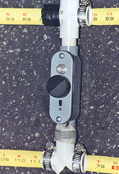
Foxhunt gear – offset attenuators
I attended a great fox hunting presentation at Dayton this year, hence a few posts on the topic.
I had some posts in the past about tape measure beam antennas. Really neat antennas and they have multiple purpose use (they are GREAT for hitting distant repeaters when you orient them vertically!). Much like the picture on the right (courtesy of Joe Moell K0OV) they are more useful for fox hunting when you add the active attenuator to your setup. FYI, Joe is the co-author of the great book “TRANSMITTER HUNTING, Radio Direction Finding Simplified” available where most ham books are sold. His website has more information on the book at http://www.homingin.com/THRDFSinfo.html and he contributes to CQ and CQ VHF.
So….. just what is an offset attenuator? Joe explains it on his “Homing in” site as:
An RF attenuator is a device that goes between antenna and receiver to reduce the signal strength down to within the range that the receiver S-meter can handle. Without one, you may think you’re close to the fox when you’re still far away. You won’t be able to get close enough to a camouflaged hidden T to identify it. The amount of attenuation should be adjustable so that you can add just a little when your S-meter first pins, up to a lot as you get within a few feet. Special ARDF receivers used by champion foxhunters have electronic attenuation built in, but ordinary handi-talkies don’t. Adding it would require major micro-surgery in the HT.
His attenuator page is:
http://www.homingin.com/joek0ov/offatten.html
I recommend his site in general, many great projects:
On his attenuator page, he has full schematics to make an offset attenuator.
But wait…… there’s more!
Further on his page, you see one made in a sweet Pomona box.  I like this box and thought it was a bit pricey at first, until I did the math and figured out the cost/time to do it myself. These boxes are shielded with the connector of your choosing (BNC/SMA/259, etc).
They generally cost around $25 or so and are shielded! Great to have. When you add the cost of connectors and such, it isn’t really so expensive after all.
I really advise using such a case or a metal case in general, makes things work out much smoother in the end. More information on this box at: http://www.pomonaelectronics.com/index.php?i=prodsub&parent=BOX&cat=BONCONN&getDetails=
But wait….. there’s even more!
 Marvin Johnston KE6HTS is now offering a “semi-kit” for this attenuator on his website. I’ve seen this kit when I was at Dayton this year and encouraged a friend to pick it up and build. I may end up running a buildathon here in CT on these attenuators.
The price is really not bad at $22.00. You can purchase them built for a few dollars more.
Information on the kits and pre-built models are at:
http://www.west.net/~marvin/k0ov.htm
And yep……. there’s even more (again!).
If you would like to “roll your own” from parts you may have on your bench, but don’t want to make a circuit board, you can get one from……. you guessed it…… Far circuits. I picked one up and am going this route myself.
There are a few boards/projects on the Far circuits website at:
There are a ton of great resources out there on the web, these will really get you going right from the start. Fox hunting is a really fun and useful part of our hobby and one that doesn’t cost a ton of money to get started in. If there are no active fox hunts in your area – start ‘em! There are plenty of options as far as transmitters and such and really doesn’t cost a club much money to get started.
More on the Minimalist Transceiver

'The Bay' minimalist transceiver (without component values)
Back in March I wrote about my experiments with a minimalist transceiver design that was published in Sprat earlier this year. Today I received an e-mail from Claude, W5FYI, who enquired about this work. He wrote:
I, too, am interested in building G0EBP’s FET transceiver. One thing that puzzles me is reference in the Sprat article to the 560pF C5. Tony says it is for the final filter. Is he referring to the FET’s capacitance, or his value for the pi filter’s capacitors.
When you get your schematic ready, please let me know.
I thought I would share my reply as others may be interested:
Thanks for the e-mail.
Yes I wondered about that reference to C5 too. I presumed it was the 100nF cap connected to the drain and the inductor on one side and the filter on the other.
I have done quite a few mods to this circuit and still tinkering trying to get a 700Hz freq. offset on transmit, so avoiding issues if someone is zero beat. My first attempts were poor, using an idea in Solid State Design for the Radio Amateur, which plays with some feedback in the oscillator circuit (Fig 6 p36 if you have that book). I see a brief freq. shift and then it seems from my freq. counter the oscillator locks back again. Perhaps I need to switch in the capacitance with the crystal which I think will work better. Been too busy recently with work to finish this experimentation.
Back to my main changes that I did.
1. I changed the oscillator to a FET based Colpitts with a J310. Better waveform, but lower output than a 2n2222 and hence only about 1/4W out with 9V.
2. I have used a different muting process. On keydown I put +Vsupply to pin 7 of the LM386. That mutes the audio op-amp. See LA3ZA, Sverre’s notes on this at http://www.qslnet.de/member/la3za/Pixie_mute.htm
3. Rather than have the key in line with the supply I included another transistor (PNP BJT) so key is connected to ground for transmit. This helps if you mount an un-isolated socket for the key jack in a metal chassis.I need to finish off the experimenting with the offset and then write up the changes for SPRAT.
I looked in my notes and see I blocked out the basic circuit but have not added any component values, so I attach it here, to help you. The offset circuitry is not included. I think you will be able to work out the component values from the original diagram. If you need the calculated values for the Colpitt’s oscillator, let me know and I can supply those.
Hope the above helps you.
By the way I have started to call this transceiver “The Bay” after Morecambe Bay where G0EBP lives and coincidentally where I was born and grew-up.
The draft circuit diagram is above. It is unfinished but still gives a good idea of what I have done with Tony’s, G0EBP circuit.
When I get time to return to this circuit I will report findings and updates here on the blog.


Polar Bear Summer Picnic Event Jun 2010
My favorite QRP group is the Polar Bear QRP gang! We have a good time and enjoy outdoors activities and trying to connect with one another at least once a month with some kind of activity. To escape some of the heat, I got an early start on the day. I wanted to try out a new mini-bac antenna configuration and knew it would take some time to get it up into the trees. BOY WAS THAT AN UNDERSTATEMENT! It was 110 ft doublet with a 40 ft feedline that was setup as a ladder line. Not an easy one to get up single-handed. Thanks to some tall trees, was able to get it up about 40-45 feet in the pine trees. It loaded great on 40m, but was disappointing on 20m so I ended up setting up my W3EDP in an L from my 20 ft Jackite pole to a nearby cedar tree at about 35 feet. The sun chased me into the treeline where I settled in to chase bears.

Abandoned mini-back doublet feedline hangs in foreground
My xyl Connie took a picture that shows the mini-back feedline hanging in the breeze after I shifted positions and setup the W3EDP in the shade. Grrrrr!

Osprey perched right above my head…cell phone picture
Was able to work a couple of the Polar Bears, Mike W3MC in MD and Guy N7UN up in the mountains on a trail(?) in NJ. I heard VA2SG but he was at ESP level briefly then faded away. I did hear a few others working him though. WA8REI was working Guy but I could not hear him at all and ended up tail ending their QSO to connect with N7UN.
Got to work a few others through the QSB and poor signal strength on 20m including Pastor Les, K4NK in SC, KE5SBZ, Ed in TX, N1FJ in MA, and Phil W3HZZ in Atlanta so it was a nice way to spend a few hours outdoors in the heat.
Connie brought me a picnic lunch and we enjoyed the osprey and bald eagle show as they fished Lake Fredrica.

Had to drink extra coffee to copy speedy W3MC's signal

This is the life… outdoors and ham radio…making QSO's…PTL!
The Montreal Doppler
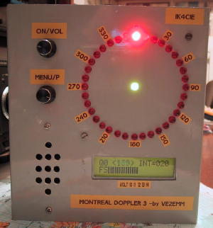 So, here I was at Dayton a few weeks ago and decided to check out the fox hunting/amateur radio direction finding (ARDF) forum. I forgot who did the forum, but it was actually very well done. One of the projects I learned about was “The Montreal Doppler”. This is a really neat project designed by Jacques Brodeur, VE2EMM.
I saw many neat attenuators, offset attenuators….. but this….. well…. it has LEDS! Pretty lights…. OK, I digress. Working with a bunch of these LED’s is pretty kewl and looks sweet. This is a project that is well documented on the web and I’ll provide links below.
The biggest question I had was, where do I get the microcontrollers and firmware. Not only was I able to acquire the PICS (microcontrollers), but I was able to get PC boards and the LCD for a very reasonable price from FAR Circuits! I know I picked up the last one he had at Dayton, but he may be able to do more (they cost $45.00). Check out the FAR circuits website at http://www.farcircuits.net/
A little about this project from VE2EMM’s website, list of features:
– 36 LEDs display; center LED when green = good signal, when red = no signal , the direction is frozen to the last good signal.
– Uses 3 PICs; a PIC16F628A for the display, a PIC18F4520 as the main processor and a PIC12F675 as a frequency divider.
– Filters; a Max 267, the best bandpass filter that I have ever seen, followed by the Roanoke switch cap filter for very narrow band width (+/- 0.5Hz).
– My DopplerII integrating and phase detection software in the main PIC.
– LM386 for monitoring the audio independently from the doppler.
– Simpler menu selection, turning a selection pot and a pushing a DO switch.
– It will switch 4 antennas with a + or – going signal, 4 antennas differential, 8 antennas with a + or – going signal.
– Pushing the DO PB sends the direction to APRS. The protocol is: <cr><lf>%359/Q<cr><lf>. The Q (0<8) is the quality of the signal just before the
extraction of the phase information.
– GPS information goes through the doppler, it will be instantly interrupted when the doppler sends a DF to APRS on a PC.
– Faster main processor, PIC18F4520. **** NEW **** June 06
The model I saw really intrigued me and there are a few really well done websites devoted to this project (it has quite the cult following).
The original site is at:
http://www.qsl.net/ve2emm/pic-projects/doppler3/doppler3-e.html
Here is another page on Jacques site that has some examples from other builders:
http://www.qsl.net/ve2emm/pic-projects/doppler3/md3_photos/dopler%203%20pictures.html
KA7OEI has a neat page with a bunch of information on this project:
He has a lot of information about an alternate firmware that looks like the image below:
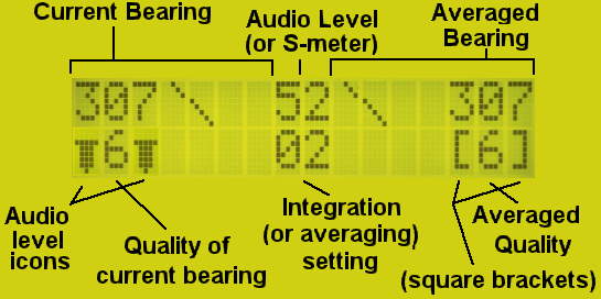
The alternate firmware page is at:
http://ka7oei.com/emm2_mont2a.html
If you have any more information on this project, resources or anything of the sort, please comment below.


