Posts Tagged ‘amateur radio’
 An editorial about the current state of Amateur Radio manufacturing
A reader sent this comment on my post about Heathkit’s demise:
“It would be a limited customer base, as with all the China crap coming in
hard to compete. Also noticed that they are selling 2mt/440 ht’s and
advertising that you do not need a license!!!look for interference to
public service and emergency com, reports against amateur radio, going
to be a tough nut to crack”
I have to disagree. First of all, some of the “crap” from China is actually pretty good, and giving the “big 3” some serious competition. You know, there was a time, back in the early seventies when everyone referred to the influx of Japanese-manufactured electronics as crap too. I remember this first-hand, as my interest in SW and AM DXing started in 1972. Look where that has gone. The Japanese are now the manufacturers of choice for our radios. Now, I cannot say that all of these new low cost radios are good (first-hand experience with a radio from FDC backs that up for me), but the BaoFeng UV-3R has set a new bar for value in a low-cost mini HT, as well as the highly-regarded Wouxun radios. It should be interesting as these companies evolve. Mobile radios are just starting to trickle in now, and who knows what’s next. Outside of radio, what about smartphones? Where are most of them made?
I watched this same thing happen with Shortwave receivers over the last decade. Companies like Degen, Tecsun, and Kchibo, first got into this market by being the manufacturers for labels like Grundig-Eton. The early radios were not good, but then a funny thing happened. The engineers listened to the public and made changes. They adjusted the performance and feature-set of these radios based on what the users were asking for. This is something that their predecessors never did. Sony, Panasonic, Philips, and even Taiwan’s Sangean, rarely made changes based on the enthusiasts comments and reviews. The result is that some of the best performing portable SW receivers for the money now come from China. Panasonic, and Magnavox, are out of the market here. Sony only makes one viable offering now, and Sangean continues to get mediocre reviews, after such a promising start. I personally own a few Tecsun, and Degen radios and although the build quality is not quite as good as the Sony, it’s VERY close now.
As far as selling to the non-licensed public, that problem has always existed. I don’t think that you were required to produce a license to buy any of the HTX radios at Radio Shack in the eighties and nineties, as well as the various commercial offerings they had. You were told by the packaging, and again in the manuals that you were required to have a license. Very few people at hamfests and flea markets ask for licenses before taking the cash from their potential customers. Add to that garage sales, and classified ads, and you can see that the ability to buy un-authorized radio equipment has always been there. Recent experience with jamming in my area led me to a small history lesson while investigating the source of the interference. This has been going on for a VERY long time, and you’d be surprised how much of the problem is caused by licensed Hams.
Craigslist, and eBay have made this easier, yes, and I believe that the equipment being sold should at least be restricted to its intended purpose (limiting Xmit frequencies for Amateur equipment), but we will never stop the sale of equipment to the unlicensed public, just as we will never stop music and software pirating.
The biggest travesty here is the existing players not recognizing the changing market. Kenwood’s new rig is gorgeous, but is another multi-thousand dollar rig what this hobby needs? What the HF side of the hobby needs is a competent, basic 160-10 (or 6) transceiver that can keep the interest of a newly licensed ham going, with a target sell price UNDER $500. 50-100 watts would be ok at this price-point, with the option of adding some power later. I honestly feel that if Kenwood, Yaesu, and Icom don’t wake up, and adjust to the changing market, they might go the way of the classic Shortwave manufacturers.
Sorry for the long editorial, but this is a sensitive subject for me. I have only been a ham for 9 months, and with all of the obligations I have, and trying to make sure there’s something left for retirement, plunking down $1000 on a radio at the moment is out of the question. Many of our new hams are in this same position. Instead of having most of us stay as Technicians, it would be nice to get these new hams interested in something other than their newly acquired VHF/UHF privileges. A General ticket is a fairly small step from Technician, and having some economical starter radios would help
Some of the kits, in my Kit Roundup post fit the bill, but most are CW kits. The SSB kits available are usually low power. There are a couple of examples with a bit more power, but fully assembled the price is already in the Alinco DX-SR8 range. Having said that, the Alinco is probably the closest rig to what I’m thinking of price-wise, but seems to get rather mediocre reviews. I guess for $519 you can’t be all that picky.
This is all my own opinion of course. Feel free to discuss in the comments.
–Neil W2NDG
Ham Radio Instagraming Fool
Well, I haven’t really posted an Amateur Radio story in a looong time, so I figured I was due. Hopefully, many people didn’t miss me too much. But I’m working on a couple ideas for the blog here, that will allow me to have some good stuff for you to enjoy without me getting all burnt out.

My newly repaired rig in one of my Instagram photos.
But in the time I was away, I did get a smart phone finally. For those wondering, an iPhone4S, and I love it. And one of the things I found I liked doing with it, is taking pictures with the 8MP camera that is built into it. The photos always seem to come out looking great. And I have already found a few neat accessories I would love to have available for myself for taking photos and even recording audio. Then allowing me to blog on the go and put up content as soon as I have recorded it or snapped a picture. And then have it of course, propagate out to the various social media sites I frequent.
Since I got my phone, it’s like a paradigm shift has occurred with the media I want to produce. It all seems so much easier and simpler to create it, then share it. All from one or 2 devices, where before, I had to use 5 or 6 devices. It really is empowering. I’ve started with just taking photos with the Instagram app and posting those on my Twitter and Facebook pages. And I’ve also started to play with another app called Blip.me Broadcast, which allows you to record 60 second audio clips and share them as well. Once I figure out how to integrate these into this site, it’s going to be a lot of fun doing this stuff! Till then, here are a few pics I took with Instagram. They of course are Ham Radio related.
73.


[adrotate banner=”12″]
Handiham World for 09 May 2012
Welcome to Handiham World.

You can do it!
Today, just as we did last week, we are going to begin with Troubleshooting 101 as part of our initiative to help new ham radio operators (and even some of us older ones) learn how to do some basic troubleshooting for ourselves. Yes, it can be tempting to ask someone else to do things for us. This can become a bad habit when it keeps us from learning new things, especially things that we could – with a bit of practice – learn to do for ourselves. Knowing these basic things can serve us well in the future when no help is available.
Troubleshooting 101

Let’s get to today’s troubleshooting question:
I like using Echolink, and I’ve finally figured out how to forward the ports on my home router to my ham shack computer. The problem is that I can’t use Echolink on any other computer in the house unless I change all those port forwarding settings or use a public proxy, which isn’t always available. Is there anything else I can do to make Echolink a little more convenient?
Echolink is pretty addictive, and it’s easy to understand why you would want to be able to use it all around the house, perhaps even on your laptop while seated out on the patio one of these nice upcoming summer days. As you discovered, when you set up your home router to forward ports as described on the Echolink website, the application will then only work on the computer you selected. The router will happily direct traffic through those open ports, but only to that one specific ham shack computer. As you discovered when setting up your home router, port forwarding is not something you can do on a moment’s notice. You have to log into your router’s web-based administration page, go to the advanced settings, and then the port forwarding section. When you make changes to the settings, the router may momentarily drop internet connectivity and perhaps even reboot. Then it will take a while for everything to settle down and work again. This can be a major aggravation if you have other users in your household or if your home phone is a VoIP system that depends on the internet being connected.
Let’s examine our Echolink application’s built-in Firewall test. You will find it by opening Echolink, going to the “Tools” menu, and arrowing to the “Firewall/Router Test”. Once there, press
Since you have already told us that your ham shack computer has Echolink working, you should get this “Testing Complete” message that says “Firewall test results: PASS”. 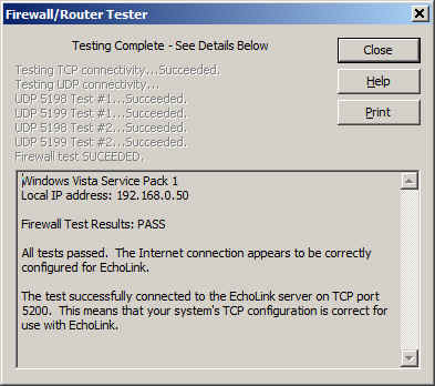
It is important to know about this handy little tool that is built into Echolink because you are going to use it again on a fairly regular basis once you make a few simple changes to your router settings.
Now it is time to use your main computer, which is connected by a LAN cable (preferably) to the router, to open the router’s administration page. Depending on your router’s setup, you will need to log in, then go to the advanced settings page and then to the port forwarding page. This should all seem familiar as you have already done it once. Next, you will need to uncheck the port forwarding boxes that you already set up. Yes, I know it seems crazy, but it is a necessary step. Save the settings, then go back to the advanced settings page and choose “port triggering” or “application rules” this time. It is similar to setting up port forwarding, but there is a BIG difference: You are opening ports when the Echolink application calls for them to carry traffic, no matter which computer on your network is running Echolink. This means that when you open Echolink on your wireless laptop while on the patio, the ports will be open to that computer. When you close Echolink on the laptop and later that evening you go back into the ham shack to use your main computer, Echolink will then work on that one because the ports will be opened by the “trigger” of a call for traffic to that machine.
I happen to have a D-Link router, so a screenshot of the application rules (triggering) page shows that I have triggered ports 5198 and 5199 for UDP traffic and port 5200 for TCP traffic. 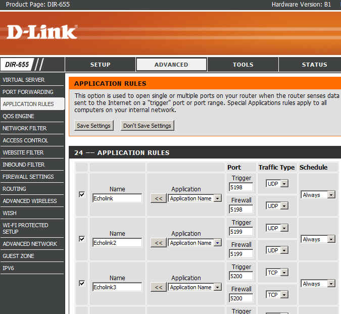
Now I can save the settings and after that I should be able to use Echolink on any computer on my home network without having to worry about port forwarding.
There are some things to remember:
- Only one computer at a time can be running the Echolink application. If more than one computer is running Echolink, only one of them will actually connect properly.
- When you close Echolink on one computer, it may take a few minutes for the network to resolve itself back to a neutral state. If you try to connect Echolink on another machine immediately, it may not work. Always allow a few minutes between switching machines – Both machines may be running and connected to the network at the same time, which is not a problem. It is only starting Echolink too soon after just closing it on another machine that can cause problems.
- This is where we try our built-in Firewall/Router tests again:
If the network is ready, the tests will proceed normally with a “PASS” and you are good to go for Echolink fun!
Email me at [email protected] with your questions & comments. But for the record, please remember that I am NOT tech support for Echolink or your home networking equipment since you are there at home and I’m here in Minnesota. Reading the manual will get you way farther than calling me for sympathetic head-nodding.
Patrick Tice, WA0TDA
Handiham Manager
More KX3, iPad and PSK-31 Experimentation
Last week I created a YouTube video to document some experimentation I had completed with the KX3, my iPad and the iOS PSK-31 app called PSKer. This week I made some modifications to my setup. This included adding a USB extension cable and I experimented with the VOX settings of the KX3.
Thank you for watching!
73 de KD0BIK
Icom IC-E92D – Why This Is My ‘Staple’ Handheld
 |
| Icom IC-E92D |
 |
| Built for the outdoor life - with HM-175 GPS Speaker-Mic |
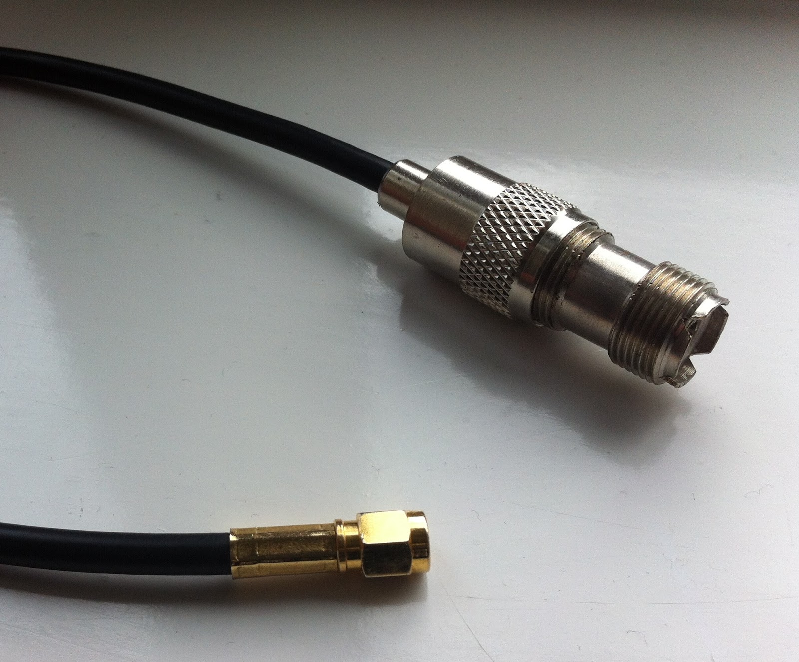 |
| SMA - SO239 adaptor |
Nice addition to the kit roundup
I constantly search for new kit sources for the kit roundup list. Today I stumbled on this one:

Kit Radio Company KRC-1
–Kit Radio Company – KRC Kits. http://kitradio.co.uk/page2.htm This UK-based company produces several interesting kits including receivers,
transmitters, and accessories. All prices are in British Pounds.
- KRC-1 superhet receiver. This receiver covers MW, and SW (160 thru 40 meters). Built in a 5-stage process for education. 1) Medium wave TRF receiver driving an earphone. 2) Audio amplifier providing speaker output. 3) The TRF receiver is converted to an IF amplifier 4) Mixer/oscillator converting the receiver to a four band superhet. 5) BFO to enable CW/SSB to be resolved. £65.99 plus S&H
- KRC-2 regenerative receiver. Covers 1-30 Mhz. in 3 bands. Regeneration with a difference. The regeneration setting on the KRC-2 is unaffected by the receiver tuning or the antenna coupling. How is this achieved? The regenerative stage is fixed at 10.7MHz and used as an IF amplifier. This one reminds me of the Radio Shack Globe Patrol regenerative I built as a kid. £54.99 plus S&H
- KRC-4 beginners TRF receiver. 2 bands; 800KHZ to 1.6MHZ and 4.0 to 8.0MHz. A TRF receiver designed for the beginner. Using a reflex circuit this receiver employs only one transistor. Band selection is achieved with two plug in coils, these are pre-wound and both coils come as part of the kit. £24.99 plus S&H
- KRC-5 direct-conversion 80 meter receiver. Designed around two well proven chips the SA602 and LM386. Employing a VFO that can be calibrated to fulfill your requirements. £25.99 plus S&H
- KRC-X-1 QRP transmitter. Covers 7, 10 and 14MHz. All you do is plug in a different crystal assembly to change band and re-tune the antenna. 0.5 to 2 watts output. £69.99 plus S&H
- KRC-X-2 80/160 meter transmitter. A simple cost effective transmitter covering either the 80 or 160 meter bands. It provides 2 Watts of RF power when operating from a 12 Volt supply. With a peak output rising to 8 Watts if external modulation is applied. Please specify 160 or 80 meters when ordering. £33.99 plus S&H

Kit Radio Company KRC-X-2
Handiham World for 02 May 2012
Welcome to Handiham World.
You can do it!
Today, just as we did last week, we are going to begin with Troubleshooting 101 as part of our initiative to help new ham radio operators (and even some of us older ones) learn how to do some basic troubleshooting for ourselves. Yes, it can be tempting to ask someone else to do things for us. This can become a bad habit when it keeps us from learning new things, especially things that we could – with a bit of practice – learn to do for ourselves. Knowing these basic things can serve us well in the future when no help is available. This next simple exercise is one that we will be practicing at this summer’s Radio Camp. You can do it yourself once you learn a few basics.
Troubleshooting 101
I have my General Class license now, so I decided to put up a vertical antenna, which I ground-mounted, in my back yard. I have checked the SWR (standing wave ratio) and it is practically one to one. It is grounded with a ground rod right near the feedpoint, and I have kept the grounding wire short. I am putting out plenty of power with my 100 watt rig, but I am having a hard time making contacts? What is wrong here?
Vertical antennas have long been the subject of derision in many amateur radio circles. It is practically an article of faith that “a vertical antenna is one that transmits equally poorly in all directions”. These operators have either tried vertical antennas themselves and had a poor experience or (more likely) they have heard some know-it-all pontificating on the awfulness of verticals and the awesomeness of just about any antenna other than a vertical.
Yes, the poor old vertical has gotten a pretty bad reputation. But is it justified?
I say no! And here’s why.
The most common vertical antenna design is an electrical quarter-wave long. This means that a simple 20 meter vertical will be on the order of 16 to 17 feet tall (5 meters). There is no problem ground-mounting a vertical in most locations, and this kind of antenna is sometimes disguised as a flagpole in places where there are restrictions on traditional antennas. A ground-mounted vertical will certainly have other advantages, too. It will not require an expensive tower or other supporting structure. It will be easy to install and work on if it needs maintenance or adjustment because you can reach it without any climbing. You can trench the coaxial feedline under the ground to keep it out of the way. If it is mounted in the back yard, it will probably not even be visible from the street. No wonder this simple antenna seems so attractive!
But let’s get back to your troubleshooting question. You have done well with your vertical antenna installation as far as it goes, but you have made a common mistake. You have assumed that a ground rod would suffice as a complete grounding system – but it won’t. When we work with RF (radio frequency) energy, we must remember that RF grounding is not the same as providing a simple electrical ground for low-frequency AC, DC, or lightning protection. Yes, a good electrical ground is an essential part of a well-designed antenna and feedline system. Now it is time to complete your vertical antenna installation with a good RF ground. That means installing radial wires extending from the base of the antenna outward in all directions. The ground rod should work as a common connection point. The coax braid is connected to the ground rod or the antenna’s mounting post, both of which are tied together with a stout, solid conductor.
What is happening in your antenna system is that lots of current is flowing in the vertical element right near the feedpoint. This is normal and expected. There is also a lot of current flowing in the ground beneath and around the antenna, outward in all directions. That is because a quarter-wave vertical is like one side of a dipole system, except that the ground makes up the other half of the dipole. If you recall your General Class studies, you will remember that current in a half wave dipole flows most strongly right near the feedpoint.
Now, answer me this: If you put up a dipole with one leg made of a fully-extended wire and the other a very short wire connected to a big resistor, do you think that dipole would work as well as a dipole with both legs made of wire?
No? Why not?
“Well”, you say, “It is obvious that the dipole with a big resistor in it will not work as well because there will be power lost in the resistor. The resistor will heat up, just like a dummy antenna.”
Yes, you are right! In fact, dummy load antennas are really nothing more than resistors designed to dissipate RF energy to keep it off the air while you run tests on a transmitter. A dummy load will have a near-perfect SWR, even though it is a resistor. Just because it has a low SWR does not mean that it is a good antenna. The problem with your vertical antenna system is that it is like that dipole with a resistor in one leg. The ground beneath the antenna has resistance to the flow of RF energy outward in all directions. The soil does have some conductivity, but it depends on moisture and composition. So the ground can be like a resistor. The ground rod you have installed goes straight down and does nothing to help RF flow in all compass directions outward near the surface of the ground.
The fix: A good radial system.
Radial wires are installed like the spokes of a wheel, outward from the grounded side of your antenna’s feedpoint. They can be cut to a quarter-wave length for every band you plan to operate (if your antenna is a multiband vertical) or – and this is more practical – to whatever length is convenient to fit into the space you have. Mind you, this goes only for a ground-mounted vertical in an area with normal to good soil conductivity. If you are mounting a vertical over quartz rock with almost no soil, the tuned radials might be necessary. If you are in the USA Midwest with its rich soil, you can probably get by with random length radials in your ground-mounted system. The reason is that conductive soil pretty much detunes the radials anyway, so there is nothing to be gained by carefully measuring them. In fact, since most of the RF current will be flowing right near the feedpoint, it makes sense to provide it with a low resistance path there, close to the antenna.
Why? Think of the formula power dissipated = current squared times resistance. The higher the resistance in the ground, the more power will be dissipated as heat. You don’t want that! What you want is for most of the power to be used to make contacts with other stations. The earthworms will be happier, too, because they don’t need the extra heat. If most of the current flows in the ground near the antenna, then THAT is where you need to put the most radial wire. I have always simplified this concept when teaching about vertical antennas by using the following practical example:
You have a coil of wire to use for radials. It is 100 feet long and will provide the radial system for your 20 meter band quarter-wave vertical. The question is which of these choices would be better:
A. One long radial that uses all 100 feet of wire.
B. Two 50 foot radials running in opposite directions.
C. Three 33 foot radials spaced 120 degrees apart.
D. Five 20 foot radials spaced at 72 degrees apart.
If you were thinking about losses near the feedpoint, you would probably pick answer D. The reason is that you are putting more wire near where the loss is actually happening! In fact, the thing with radials is “the more, the better”, not “the longer the better”. Of course you would not want to go to extremes and assume that 100 one-foot radials would work. But in the real world, you want to get more wire down in the ground near the feedpoint. A dozen radials work better than four.
Installing and testing the system:

Stomp the grass back down and you are good to go. Repeat for each radial. If you can go out 33 feet in one direction and only 15 in another, that’s okay. Just make sure that the final installation is solidly connected to the ground rod and coax braid and all of the wires are out of the way of the lawn mower. The insulated wire will last longer in the ground than non-insulated wire. Once you get a taste of a hands-and-knees radial installation, you will not be eager to repeat it to replace rotted out wire any more than you have to. And if you tried to install springy radial wire, well, you know what that is like. Push one part in, another part pops out.
Email me at [email protected] with your questions & comments.
Patrick Tice, WA0TDA
Handiham Manager


