 |
 Another good day!
Two for two Thursday, let’s call it!
Second day back to lunchtime QRP operating, and another good day. The higher bands were alive again. This time I worked Russia R2014ME (I had worked R2014E yesterday), Belarus EW8O and Mexico XE2I. And …. for the heck of it, I wanted to see if I could break the monstrous pileup that was foisting itself upon W1AW/5 in New Mexico. 15 Meters was hot and the band was long. The amount of European stations calling W1AW/5 was huge and LOUD! Would it be possible for a QRP station, powered at 5 Watts to break that melee?
Not only was is possible, but it happened. I made it into the log. But it took some listening and some figuring. The W1AW/5 station set up a pattern. He was working split, and was announcing “U”, which of course meant that he was listening up. But he was listening “in an race track pattern” as it were. By carefully listening for a while, I was able to determine a pattern:
1) W1AW/5 works a station
2) W1AW/5 moves the listening frequency up a few Hertz
3) W1AW/5 works the next station
4) W1AW/5 moves the listening frequency up a few Hertz
5) W1AW/5 works the next station
But he did this only to a point. Once he reached a point known only to him, he reversed the procedure. He would work a station and then listen a few Hertz DOWN from the last station he worked. He kept doing this until he reached a “lower UP frequency” that he determined and then started the whole business over again.
If I didn’t make myself clear (sometimes I have a problem doing that), what he was doing was changing his listening frequency in a circular pattern, even though he was always listening “UP”. For example – W1AW/5 was on, let’s say 21.030 MHZ – he was working stations between 21.031 and 21.034 MHz. And he was ping-ponging between the two. He would start listening up at 21.031 Hz and would keep moving his listening frequency until he hit 21.034 and then work back down to 21.031 and then back up to 21.034 and so on and so on and so on.
After determining what he was doing, I adjusted my transmit frequency to “get in his way”. After about three or four minutes of trying, I was able to make myself heard. Now I suppose that if I didn’t listen as much as I did, I might have made it into the log anyway, just by sheer dumb luck. But by determining what he was doing, I shortened the time (considerably, I think) that it took to get into his log. And during these lunchtime QRP sessions, time is a precious commodity, so saving time is a very good thing.
As I’ve stated before, I’m not going out of my way to take the pains to work all 50 W1AW stations. However, today I sensed a challenge that I felt like taking on. It’s good practice for the Fox hunts and those pesky DXpedition pileups.
Speaking of the QRP Fox hunts, I am one of the two 80 Meter Foxes tonight. This is my last stint of the 2013/2014 season. It’s been fun and I hope to hand out a lot of pelts tonight. As a Hound, this has been a particularly exhilarating season! According to the last tally – I have worked 25 out of 32 Foxes on 40 Meters (78%). On 80 Meters, I have worked 24 out of 30 Foxes (80%). This has been my best season – ever! The season ends in just a few weeks, and I hope to continue with a strong finish. Wait a second, I probably just went and jinxed myself! Then again, I guess I can’t really jinx myself as I owe all my success to the extraordinary ears and antennas of the Foxes.
One last note. If you get a chance, take a gander at the February 2014 edition of CQ magazine, if you can get your hands on one. There’s an article on my lunchtime QRP sessions that was written and submitted by yours truly. Rich W2VU felt it was worth including – hopefully by accepting my article, he’s not scraping the bottom of the barrel too hard!
72 de Larry W2LJ
QRP – When you care to send the very least!
Larry Makoski, W2LJ, is a regular contributor to AmateurRadio.com and writes from New Jersey, USA. Contact him at [email protected].
From Russia with Love…
Its been to many months since my last lunch time QRP session! Finally had a warm day with no work activities over lunch so I headed out to my favorite park and had a blast!!
As soon as I turned the KX3 on I heard…
KC2EE calling CQ on 14.060 – we exchanged 559 reports – he was in Houston, TX. Working Sid brought back the great feeling of sending some CW – although I was rusty!
Then I went on to work…
NA6MG was spotted on SOTA GOAT, so I tuned to 18.090 and there he was coming in at 599. Dan was on W6/CT-231.
OH4MDY was calling CQ on 18.075 and was a solid 599 here. I had to call a couple times, but finally made it. Retu was in Finland!
Next up was my best DX yet!
R7LA – Vasily was calling CQ on 24.893 with no takers. He really had to work to pull my callsign out, but then it seemed to get better. He copied my well after getting my call, so the conditions must have improved. He gave me a 559 and he was 599 here. He must have pulled up my QRZ page while on air because he told me that my QRP signal was FB! What a hoot! Thanks Vasily for pulling my 5 watts out of the mud, you made my day!
Not that spring is here, I will be operating much more at lunch time. I am still working on getting my home station set up. Antenna is ready, I just need to get it in the attic! I really want to start working some digital modes from home. I think they might work best because of the loud interference I experience there. We will see.
Burke Jones, NØHYD, is a regular contributor to AmateurRadio.com and writes from Kansas, USA. Contact him at [email protected].
0,5 W on 10 meter


I was happy that WA6JRW from California spotted me with 0,5 watt. That's 8875 km.
Paul Stam, PC4T, is a regular contributor to AmateurRadio.com and writes from the Netherlands. Contact him at [email protected].
A New Server
I am not a QSO monster and usually only add around 400 QSOs to my log each year. But with two new rigs and the sun helping out I already have 170 QSOs in the log for this year. And it is not even the end of March!
But I do notice that my desire to operate has diminished a bit and so it is time for some DIY again. The lightning sensor is progressing and once that is up and running it is time to tackle another problem: weather satellite reception. I have a dedicated NOAA 137 MHz receiver, which is controlled via serial port and feeds its audio to the excellent Wxtoimg program for decoding of the APT signals. Unfortunately my current server doesn’t like either Wxtoimg or the 137 MHz receiver, so the latter has been sitting idle in a corner for a while now.
Time for a new server. Even though I didn’t like the Raspberry Pi very much, I do like the concept of a small, low cost, low power consuming computer. Apart from the Raspberry Pi there are plenty of alternatives now that use an ARM CPU, e.g. the BeagleBone Black or the PandaBoard. They are more expensive, but also offer better performance and features. For us radio amateurs they usually lack an essential feature: analogue audio in. So when I read about the Cubieboard and discovered that their version 2 board has both audio-in and out I had to try it out. I ordered one from our Taiwanese version of Ebay and for US$ 71.50 it was delivered home. Twice as expensive as a Raspberry Pi, but the package was very complete, with all the cables necessary and a power supply too. Nice detail on the package: Made in China, Designed in China.

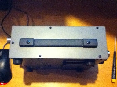
The very complete Cubiboard Package
Getting it running was a bit of a struggle, though. Finding an suitable image was difficult because I only had a 2 GB microSD card. Once I had found one it wouldn’t boot and apparently it also killed the Android OS that was installed on the NAND memory. The Cubieboard has 1 GB of RAM and 2 GB of internal storage (NAND), much better than the Raspberry Pi.

The Cubieboard. Twice as large as the Raspberry Pi. The audio input-output is on the left.
So I flashed the NAND with a new version of Android and now it was running fine. After buying a new 8GB microSD card and flashing it I was able to boot into a fresh Cubian LXDE install. It looks great on our Panasonic HD TV. So far, so good. I hope this is a winner, because I already have lots of ideas for it: remote rig, APRS digipeater, second weather station, web cam server. Let’s just wait and see.

Android running from the build in 2G NAND memory.
Hans "Fong" van den Boogert, BX2ABT, is a regular contributor to AmateurRadio.com and writes from Taiwan. Contact him at [email protected].
Back in the saddle again!
You have probably noticed my lack of activity on the blog for the past little while. It’s been a hectic, topsy-turvy couple of months. Let me explain.
On New Year’s Eve, my co-worker left work early, telling me that he “might be back” in a few hours. Turns out that he was having some medical difficulties and checked himself into a hospital. Fortunately, he healed and got better. Unfortunately, he decided not to return to work, at least not where we work anyway.. So, since the beginning of the year, I have been alone at work, and have been busier than the proverbial “one armed wallpaper hanger”. One man doing the work of two made the possibility of leaving my desk for the car during lunch just a wistful desire. Add to that, numerous snows, a colder than normal January and February, and I’m not so sure I would have headed out there, even if I could have!
A replacement co-worker was hired and started yesterday. So today, even though it’s overcast, it is warm (comparatively). It was 40F (4C) at lunchtime and I took advantage of not being alone anymore and headed out to the car for some lunchtime QRP for the first time since last December. I wasn’t sure what to expect, but boy howdy, did it turn out to be great!
It seemed liked all the higher bands were just jumping with activity – 10, 12 and 15 Meters were alive with signals and I worked someone on each band. I worked CO6RD and R2014E on 15 meters. I worked HA9RT and OH4MDY on 12 Meters, and OK1DMZ on 10 Meters. I wish I had more time as it seemed like there were people from just about everywhere on the bands!
Whoopi-ty-aye-oh
Rockin’ to and fro
Back in the saddle again
Whoopi-ty-aye-yay
I go my way
Back in the saddle again
And it feels so good!
72 de Larry W2LJ
QRP – When you care to send the very least!
Larry Makoski, W2LJ, is a regular contributor to AmateurRadio.com and writes from New Jersey, USA. Contact him at [email protected].
Handle for K2
Yaesu MHG-1 hand strap for FT-450 works great on the K2.
Ethan Miller, K8GU, is a regular contributor to AmateurRadio.com and writes from Maryland, USA. Contact him at [email protected].
Proposal for a fourth ultimatic mode: First paddle priority
The ultimatic mode is an alternative to the iambic mode for sending Morse code from a dual lever paddle. When pressing both paddles the last one to be pressed takes control, rather than the alternating dit-dah or dah-dit of the iambic mode.
In the K1EL Winkeyers there are actually three ultimatic priority modes. This is shown in the table below that comes from page 9 in the specification for the command for setting the PINCFG Register. (K1EL CW Keyer IC for Windows Winkeyer2 v23 10/5/2010). This is a de facto standard for interfacing to and controlling a keyer, as an example it is used in the K3NG Arduino Open Source Morse keyer.
 |
K1EL has defined bits 6 and 7 for setting this up by remote command. I propose that the last possibility, ’11’, presently undefined and unused, be used for a new mode. This mode is “First paddle priority” meaning that the last paddle which is pressed is ignored. It can also be interpreted as an emulation of a single-lever paddle. I and others have found that helpful in eliminating errors when keying. See for instance “Single Paddle operation with Iambic paddles” by Larry Winslow, W0NFU, in QST, October 2009 and the Iambic to Single Paddle kit from WB9KZY or my earlier blog post “Single-lever and ultimatic adapter“.
My proposal is that the bits for the ultimatic mode be used like this:
- 00 – Last paddle priority, i.e normal ultimatic
- 01 – Dah priority
- 10 – Dit priority
- 11 – First paddle priority or Single Paddle Emulation (New)
Sverre Holm, LA3ZA, is a regular contributor to AmateurRadio.com and writes from Norway. Contact him at [email protected].
 Ham Radio Deluxe |
 W5SWL Electronics |
 Ham Radio Prep |
 KB3IFH QSL Cards  Hip Ham Shirts  HamRadioAuctions HamRadioAuctions Reliance Antennas Reliance Antennas Enigma Shop Enigma Shop |  morseDX  Ni4L Antennas  R&L Electronics R&L Electronics antennas.us antennas.us QRV QRV |
- Matt W1MST, Managing Editor
